Like many readers of Nuts & Volts, you probably have a need for test fixtures. Test fixtures allow you to rapidly test capacitors, resistors, diodes, transistors, etc. Test fixtures also provide a stable environment to replicate conditions for testing so that devices of a certain type can be compared. If you are troubleshooting circuits that are already constructed, a test fixture is probably unnecessary, although an assembly can test components under actual circuit conditions. There’s also the possibility you might need to remove components for testing out of the circuit.
While assembling electronics chassis, manufacturers can build fixtures for testing multiple assemblies. It is unlikely the hobby builder will require this. Without test fixtures, discrete components that are difficult to hold while measuring their parameters create undesirable variables and conditions. If you need to test components that require high voltage for testing, a test fixture is highly recommended. New components purchased in quantity can be checked for value (such as resistors or capacitors) and other components such as LEDs, diodes, rectifiers, and transistors can be quickly checked for critical parameters. For example, if you buy resistors in quantity (100 for $2) you can check them or match them quickly.
Simple test fixtures can be designed that hold one component. One of the older connector styles — banana jacks and plugs — works very well for making test fixtures. Dual banana jacks have a spacing of .75" between the two connectors — standard across many products such as meters and generators. Pomona makes adapters with this spacing, as do many other manufacturers, so building test fixtures with this spacing is recommended. Although the frequency bandwidth of this attachment method is limited to low frequency use (under a MHz), for testing components out of circuit, fixtures using banana jacks are satisfactory and very easy to use. Figure 1 shows test clips made by Grayhill that allow quick insertion of two-lead components.

FIGURE 1. Grayhill clips with resistor.
A portable multimeter can be used with clips like these to test components as shown in Figure 2. Measurements can be made on resistors, capacitors, diodes, and inductors if the meter has appropriate scales.
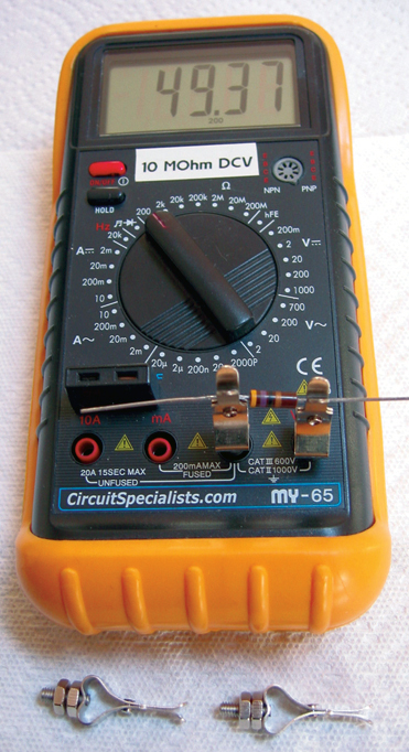
FIGURE 2. Meter with resistor.
Test Fixture Examples
A test adapter for attachment to coaxial connectors is shown in Figure 3.
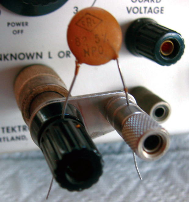
FIGURE 3. LC130 with cap.
Adapters like this have an advantage in that they eliminate the need for a lot of lead length from the measurement. So more accurate results can be obtained. Figure 4 shows this adapter in action: A Tektronix LC130 capacitance meter is measuring a small capacitor.
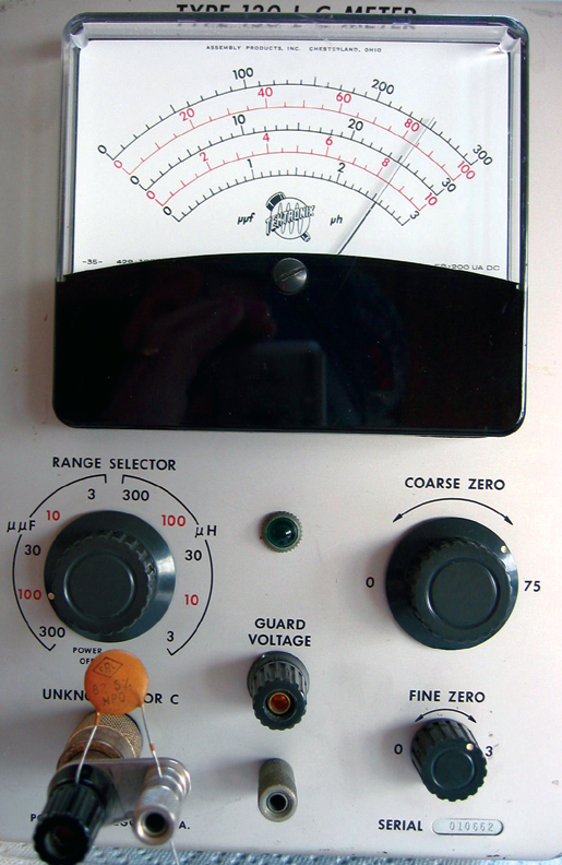
FIGURE 4. LC130 in action.
The marked value on the capacitor is 82 pF; the meter is indicating about 84 pF. Although the meter was zeroed before the measurement, the difference in reading could be from the component tolerance or the extra lead length of the capacitor. One side of the capacitor is at ground, so the lead length on that side is small. Meter calibration might be a factor, but for home use the tolerances are acceptable, and adapters like this really help.
A Simple Test Fixture
Fixtures quickly allow comparison of two devices to be constructed. Test adapters of this sort are often provided by manufacturers for their test instruments. Tektronix offered an adapter that would do this, but they are difficult to find and usually expensive. You can build a simple box with a switch and two connectors to serve this function. The fixture presented here is intended to permit attaching to a transistor/FET curve tracer.
A small plastic box is appropriate for this project. I used a blue plastic box to match the side cover colors used on older Tektronix instruments. Figure 5 shows the plastic box prepared for receiving components to attach to a curve tracer.
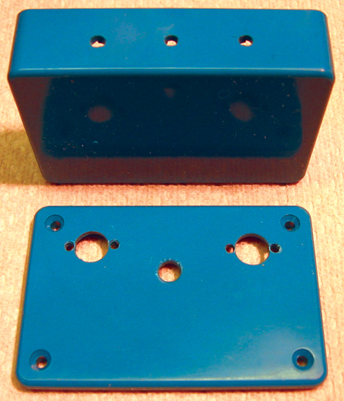
FIGURE 5. The drilled box.
Figures 6 and 7 show the components attached. (If you are using old stock components, be sure to clean the contacts before you try to solder to them.) This is the voice of experience talking.
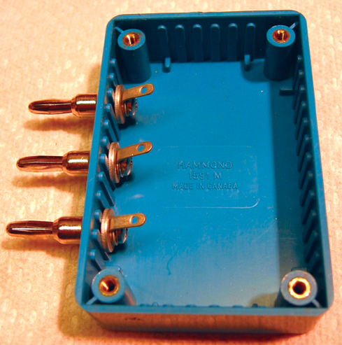
FIGURE 6. Base with banana jacks mounted.
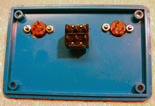
FIGURE 7. Top components mounted.
In Figure 8, the wiring has been completed. Since the emitters of the test devices are at ground, only the emitters and collectors need to be switched from one transistor to the other; a double pole double throw (DPDT) switch is required to accomplish this. The long lead lengths do not seem to present a problem in displaying parameter curves, because the curve tracer generator runs at 120 Hz. The schematic is in Figure 9.
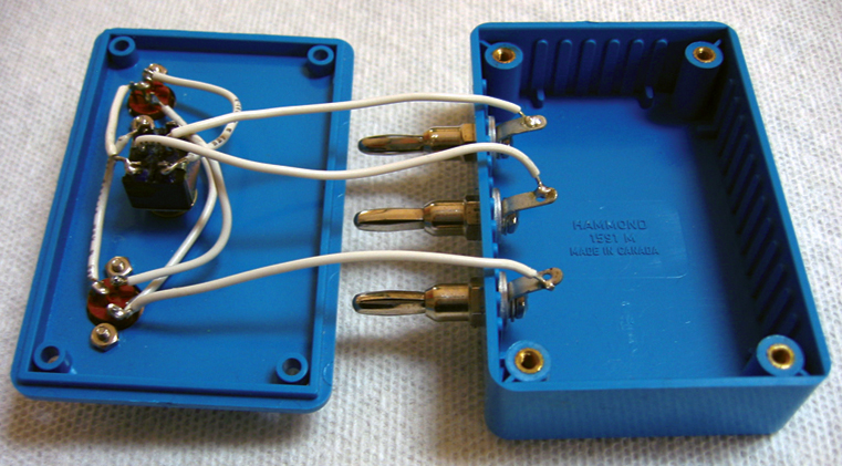
FIGURE 8. Our tester wired.
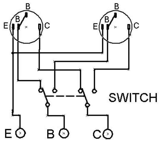
FIGURE 9. Schematic.
The sockets used to construct this device were (new) old stock, and were built to provide connections for JEDEC TO-5 transistor packages and early in-line transistor configurations. They can be used later for long lead transistors (new stock) before they have been soldered. They can support JEDEC TO-18, TO-39, TO-92, and TO-100 packages, and other configurations. Lead diameter might be the only concern in using these sockets. If you build it and it doesn't work, check the usual suspects: cold solder joints, mis-wiring, or bad components. Your ohmmeter is your friend. Remember to check the switch contacts in relation to the bat handle before you wire.
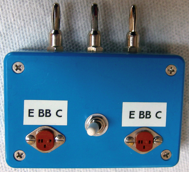
Figure 10 is the completed test fixture. Although not very beefy, it is adequate for home use. You could construct a similar device for testing SCRs and power transistors with different sockets such as TO-220, a different switch, and a bigger box.
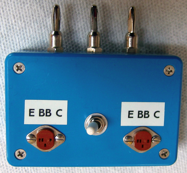
FIGURE 10. The completed unit.
Figure 11 shows the test adapter in action on a 7CT1N plug-in installed in a 7000 series Tektronix oscilloscope. The transistor on the left is under test. Since Tektronix curve tracer models such as the 7CT1N and 575 have .75" spacing for input connectors, this fixture can perhaps be used on others.
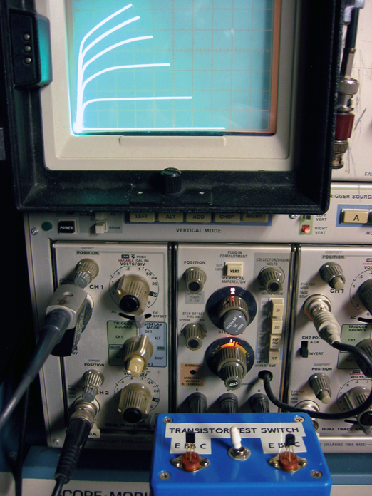
FIGURE 11. Our Tester on a Tektronix 7CT1N.
Test Complete
You will find that constructing test fixtures like this help to speed your projects along. They help eliminate errors from creeping into component selection and testing. If you have a large junk box full of components to check, test fixtures are nice to have. Setting up test fixtures for resistors, capacitors, or diodes will help you sort the junk box quickly. NV
| ITEM |
MFR PART # |
DIST PART # |
| Plastic Box |
Hammond 1591MBU |
MOUSER 546-1591MBU BLUE |
| Switch (DPDT) |
Mountain Switch |
MOUSER 1081MD1T2B3M1QEEVX |
| |
MS-100737 |
(or equivalent) |
| Test Clips |
Grayhill 02-0 |
ALLIED 9487397 |
| w/Banana Jack |
02-1 |
ALLIED 9481000 |
| Banana Jack |
Emerson 1080753102 |
MOUSER 5301080753102. |
| Transistor Sockets |
|
www.mouser.com |
| |
|
www.alliedelec.com |
BILL OF MATERIALS.
Obligatory Warning
If you acquire a curve tracer made by almost any vendor and perform testing on transistors, there will be the opportunity for the equipment to generate dangerous voltages. Since some curve tracers supply currents into the ampere range, combined with higher voltages, you must be careful not to exceed your limits. Happy testing!