Open a parts vendor’s catalog to the capacitor section and you’ll find an amazing variety of choices. Why are there all these different types? Rest assured that there are perfectly good reasons for each. In this article, I’ll explain why and how to tell what type is right for your project.
Capacitor Fundamentals
A capacitor is just a pair of conducting plates (electrodes) that are separated by an insulator (dielectric). When voltage is applied, electrons are forced onto one plate and removed from the other, charging the capacitor and creating an electric field between the electrodes. The electric field’s energy is stored in the capacitor’s dielectric. All capacitor types are just variations on this general theme.
Capacitance is the measure of the amount of energy that the capacitor stores for a given amount of charge and voltage. The area of the electrodes and the material used for the dielectric determine the capacitor’s ability to store energy. More area or a thinner dielectric increases capacitance. Like resistors, a capacitor’s value has a certain precision that shows how close the capacitance must be to the labeled or nominal value.
DC will not flow between the two electrodes as long as the dielectric material can withstand the applied voltage. AC is considered to flow between the plates as the electrons flow onto and off of the electrodes. Energy is stored and removed from the dielectric with each half-cycle. Like juggling two balls from hand to hand, there is a lot of energy transferred, but no net change. As the capacitor charges, the building voltage opposes the flow of additional charge. This opposition to current flow is called reactance and is abbreviated XC. (XL is inductive reactance.)
The materials used to make the capacitor and their physical configuration cause some variation from the ideal capacitor. The size of the electrodes and the leads used to connect them to circuits introduce a small amount of parasitic inductance. Dielectric materials dissipate a small amount of the stored energy. There is also a little leakage current between the electrodes whenever voltage is present.
These extra and unwanted effects are shown in Figure 1 as the model of a real capacitor.
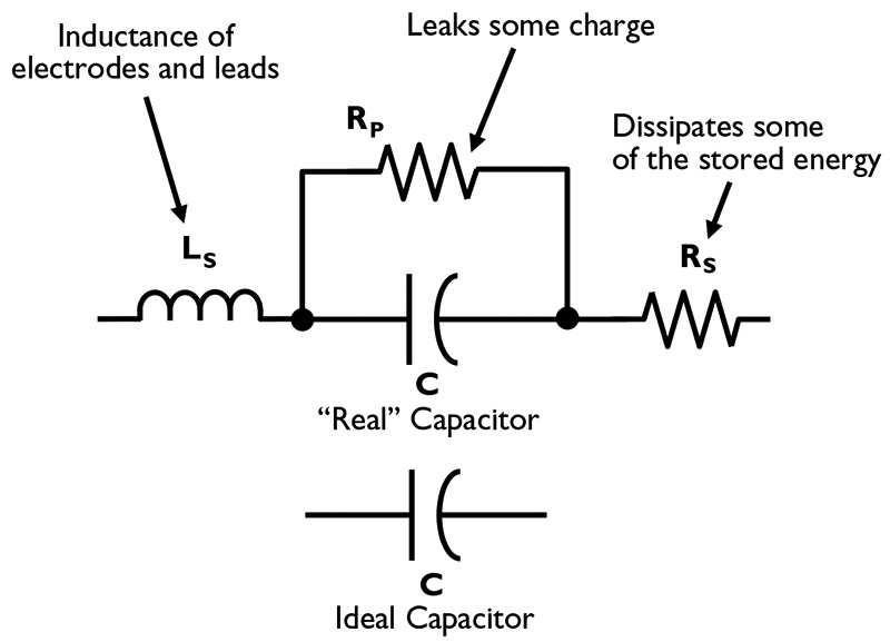
FIGURE 1. The model for a real capacitor includes inductance and loss that affect its performance.
The parasitic inductance (called ESL for Equivalent Series Inductance) is represented by LS, leakage by resistor RP, and dissipation by resistor RS. (The ‘s’ and ‘p’ stand for series and parallel.) This model works well enough to represent capacitors over most frequencies and for all but the most demanding applications.
Parasitic inductance is quite small, from picohenries to a few nanohenries. At DC and low frequencies, LS can be ignored, but as the frequency increases, so does its reactance. In fact, at a sufficiently high frequency, LS and C form a series-resonant circuit. This is the self-resonant frequency, fO of the capacitor. Above fO, the capacitor acts more like a small inductor! RS (also called ESR for Equivalent Series Resistance) acts just like a separate resistor, dissipating a little energy as heat when current flows. RS can be as high as several tens of ohms, but is generally only important when the capacitor current is high. RP provides a leakage path for current across the dielectric and is typically in the megohms. You can ignore RP except in very low-power and high-impedance circuits.
Capacitor Types
There are two common ways of efficiently making capacitors: the Roll and the Stack. Figure 2 shows a typical roll capacitor — two strips of very thin aluminum foil separated by a dielectric. After leads are attached to the foil strips, the sandwich is rolled up and either placed in a metal can or coated with plastic. Radial leads both stick out of one end. Axial leads stick out from both ends along the roll’s axis. Because of the long rolled strips, the roll capacitor’s LS is high.
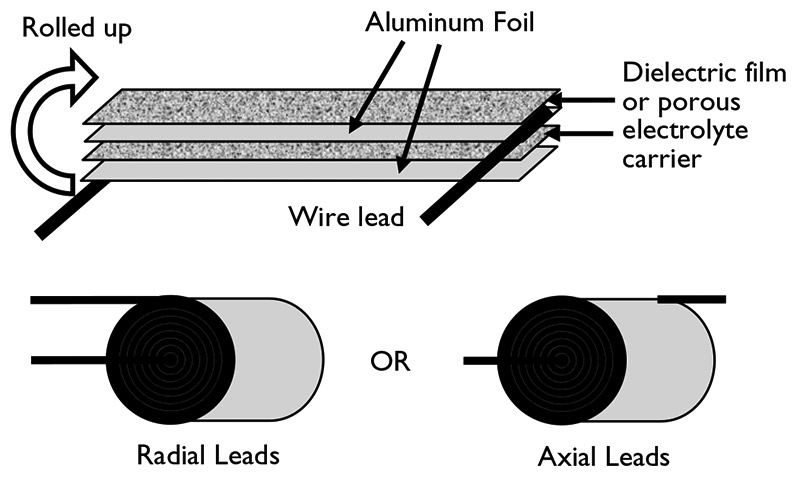
FIGURE 2. The “perfect capacitor” is made by combining the best characteristics of three different types of capacitor.
Figure 3 shows a stack capacitor. The most common dielectric (as shown) is ceramic. Each piece of ceramic is coated with a thin metal layer on one side. The stack is oriented so that the metal layers only touch one side, alternating in each layer. The stack is then placed under pressure and heated (called sintering) to make a single solid piece of material. Metal end caps with leads are attached to each side of the stack, contacting the metal layers. The whole capacitor is then coated with an epoxy resin. The LS of stack capacitors is very low.

FIGURE 3. Roll capacitors are made from strips of metal and dielectric materials rolled into a cylinder.
Electrolytic
The most common type of roll capacitor is the aluminum electrolytic. The dielectric is a porous layer of paper-like fiber, impregnated with a chemical gel that acts as a dielectric. Electrolytics have very high capacitance for their volume, but also have high LP and RS (lossy), and are relatively leaky (low RP). They can be made to withstand substantial voltages. Electrolytics are polarized, meaning that voltage can only be applied in one way due to the chemical electrolyte. They generally have very broad tolerances of ±20%.
Tantalum
Tantalum capacitors are a special type of capacitor. Instead of a roll of foil, an extremely porous “slug” of tantalum makes one electrode and an outer metal capsule the other. The dielectric is a chemical solution that forms an oxide coating on the tantalum slug for insulation. The slug has a tremendous amount of area, so capacitance is high, but RS is also high (somewhat lossy). The short leads and small size of the capacitor means that tantalums have low LS. The maximum applied voltage for tantalums is under 100 V. Like electrolytics, they are polarized and have broad tolerances of ±20%.
Film
Film capacitors have a plastic film dielectric; polyethylene and polycarbonate are the most common. Most film capacitors are of roll construction, so LS is moderate although stack types are not unknown. Film capacitors are non-polarized. RP is high (low leakage) and RS is low (low loss). Special types of film are used for highly stable capacitance values or extremely low leakage. Precision film capacitors of 5% tolerance or better are available. See www.filmcapacitors.com/specsum.htm for a good table summarizing the different types of film capacitors.
Ceramic
By far the most common form of capacitor used, ceramic capacitors are used in high-frequency applications. Stack construction keeps LS extremely low so they are useful at frequencies of hundreds of MHz. They are low-loss (low RS) and have good leakage characteristics (moderate RP). Ceramic capacitors are very rugged and pack a lot of capacitance into a small package. Ceramics are non-polarized and have a wide range of tolerances.
Mica and Glass
You will occasionally find silvered-mica and glass capacitors in RF and transmitting equipment due to their extremely low loss (low RS and high RP) and low LS. A variation on the ceramic stack, mica and glass dielectric layers are used instead of ceramic. They cannot be sintered like ceramic, so this limits the capacitance that can be obtained. Both types typically have a 5% tolerance.
Adjustable
If you take apart an old radio, behind the tuning knob you’ll see an air-variable capacitor with closely-spaced metal plates. While these are typically small in value (1,000 pF or less), they are adjustable. Air variables are stable and low-loss, working very well at RF. An adjustable variation of the mica capacitor in which the stack is squeezed by a screw is called a compression trimmer. Ceramic and plastic variables are also available with values of up to several hundred pF.
How To Make a Perfect Capacitor
There is no one perfect capacitor type for all applications, but you can make several types share their best characteristics. For example, power supplies for digital electronics need filters that take out everything from low-frequency ripple all the way up to switching transients at hundreds of MHz. Since no single capacitor is suitable, the “perfect” capacitor is made as shown in Figure 4. The electrolytic takes care of low-frequency ripple, the tantalum medium frequencies, and finally the ceramic cap takes care of everything up into the VHF range.
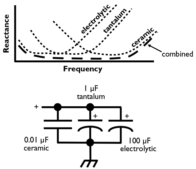
FIGURE 4. The “perfect capacitor” is made by combining the best characteristics of three different types of capacitors
How Big is a FARAD?
One farad (1 F) is a large value as capacitors go, but what does that mean? Well, if a 1 F capacitor is charged up to 12 V, it contains enough energy to accelerate a 165-gram Frisbee™ to 67 miles per hour! That’s a pretty stiff toss! Similarly, to get that 1 F of capacitance, two plates separated by air and only 1/10 mm apart would have to be 11,300,000 square meters in area! That’s 4.36 square miles!
Temperature Coefficient
The materials that make up a capacitor expand and contract with temperature, meaning that the capacitance changes with temperature, as well. In many applications, such as IC bypassing or DC blocking, a change of a few percent is of no concern. However, in a timing circuit or an oscillator, it’s a Big Deal!
A capacitor’s change in value with temperature is called its temperature coefficient or tempco and is denoted by an industry standard code. (The nominal value is specified at 25°C.) The three most common tempcos are:
Z5U = +22%/-56% change over -10°C to +85°C
X7R = ±15% change over -55°C to +125°C
NP0 = 0±30 ppm/°C over -55°C to + 125°C
As you can see, the Z5U rating allows quite a bit of change, but these are inexpensive capacitors used for garden variety applications or where temperature won’t be changing much. The NP0 (that’s a zero, not a capital O) capacitors are only used where holding a steady value is important. You can find a nice display of temperature coefficients at www.niccomp.com/resource/files/ceramic/TC_Ceramics.pdf
Choosing Capacitors
Now that you know more about the types of capacitors, here is a list of common applications and the types of capacitors used in them. The reason that type is chosen is shown in parentheses.
- Power supply filtering (60 Hz) — electrolytic (high value, low cost)
- Switching power supply filtering — electrolytics with low ESR and low ESL, film (high frequency current handling)
- Power bus filtering — tantalum and electrolytic (good medium and high-frequency characteristics)
- Digital IC bypassing — ceramic (excellent high frequency characteristics)
- Timers and oscillators — polystyrene film or NP0 ceramic (stability and precision)
- Audio filters and amplifiers — film (low-loss and small)
- Analog-to-digital conversion — low-leakage film (stability and precision)
- RF filters — silvered-mica, air variable, or transmitting ceramic (low-loss and stable)
The important thing to remember in order to make the correct capacitor choice is to think about what is important for your circuit — value, stability, cost, loss — and choose a capacitor type that meets those requirements.
SAFETY IN Primary Circuits
If your application requires a capacitor to connect directly to the AC power line (such as filtering), select a capacitor rated specifically for that use. These capacitors are rated by a safety agency such as Underwriter Labs (UL), CSA (Canada), or VDE (Europe) for “across the line” use. They are designed to be “fail safe” and not cause hazards to equipment users. The additional cost is minimal.
For Further Reading
By now, you’re aware that there’s a lot more to a capacitor than its capacitance. If you are really interested and can find a copy, The Capacitor Handbook by Kaiser (CJ Publishing, 2851 W. 127th St., Olathe, KS 66061) is an authoritative, but easy-to-read reference. NV
About the Author
H. Ward Silver is an engineer, writer, and teacher with over 30 years of practical experience in medical electronics, instrumentation design, and broadcasting. He is the author of Ham Radio for Dummies by Wiley Press and numerous articles for QST Magazine. Ward’s ham radio call sign is NØAX.