Control digital I/Os on a PIC microcontroller via your cell phone
How a novice learned PIC microprocessor development and embedded C programming while building a circuit to talk to his cell phone
The idea was to build a circuit that could communicate to my cell phone. Sounds easy? Right? After rolling this idea around in my head for several months, I decided to give it a try after reading the article Automagic with the MPLAB Code Configurator by Fred Eady in the December 2015 edition of Nuts & Volts. It was an excellent article but way over my head at the time, and the application didn’t talk to a cell phone like I wanted to do. I decided to give it a try anyway. Maybe adapt it ... how hard could it be?
Since the article that inspired me was based on Microchip products, that was the direction I headed in. So, I started climbing the learning curve. What follows are my steps up said curve that I made, just in case you’re interested in making the climb yourself.
Develop design goals
I decided to develop a circuit that would function as a general-purpose platform that would be easily adaptable to future projects. I decided on the following:
- Communicate via Bluetooth LE to my iPhone.
- Have two digital inputs for reading in data.
- Have two digital outputs for remote control.
- Have one analog input for reading sensor information.
Order a development board/programmer
I bought the Curiosity integrated programmer/debugger (eight-bit) for $20. It comes with a PIC16F1619 microcontroller and was purchased on Microchip’s website (see Resources #1). You’ll need a cable to connect the board to the USB port of your computer. I had one I used with my digital camera that worked, but if you don’t have one laying around you will need a USB male to micro B cable.
Order a Bluetooth low energy module
Since the Curiosity board comes with solder pads for the Microchip Low Energy Bluetooth module RN4020, I used it. It cost $8.83 from Microchip (see Resources #2). Alternately, I could have purchased a “BLE2 click” which is a RN4020 (see Resources #3) already mounted on a board that can plug directly into the mikroBUS socket on the Curiosity board. It would save me some soldering, but would add $30 to my expenses. In either case, you will want to download the RN4020 user’s guide for future reference (see Resources #4).
Download the required software for programming the microprocessor
Start by downloading the MPLABX IDE (integrated development environment), XC8 compiler, and XC16 compiler from http://microchipdeveloper.com/tls0101:start and www.microchip.com/mplab/compilers. The first link is to a tutorial for MPLABX IDE which is used to configure and program the PIC. Click on the “Required Tools and Files for Lab Exercises” link under Table of Contents on this page.
Download the MPLABX IDE and the XC16 complier, then go to the second link and download the XC8 complier. You’ll use the XC8 compiler for programming the PIC16F1619 used in this project, and the XC16 compiler for when you get around to working through the tutorials.
Later, as you continue to develop your skills, you’ll want to come back to work through parts of this tutorial. As of this writing, MPLBX IDE is at version 3.55 and XC8 is at version 1.36. Later versions should be very similar, but you may need to do a little extrapolation.
Learn enough embedded C programming to utilize the MPLABX IDE with the Code Configurator
The Code Configurator is part of the MPLABX IDE and makes programming the PIC significantly easier — providing you know enough embedded C programming to tie the pieces together!
If you’re following along on this journey, you can probably skip this step for the time being. I’ll provide all the C code needed for this project in a file at the article link. Once you decide to branch out on your own, I would recommend you check out an excellent embedded C programming tutorial located on the Microchip website (see Resources #5).
The tutorial covers all the basics with meaningful exercises and instructions. It uses the simulator in the MPLABX IDE, so the tutorial can be used without the development board. I would also recommend you download the PIC16F1619 code ZIP file from the Curiosity home page (see Resources #1). This download contains two useful documents: “MPLAM XC8 Getting Started Guide” and a ReadMe file with simple program descriptions that I found very useful while I was learning to code. I would recommend working through the tutorial first and then the other two documents.
Download the phone app
Download “Bluetooth Smart Data” which is available at the Apple App Store. If you have an Android phone, you’ll need to contact your local Microchip sales office for the phone app. Since I only have iOS devices, I can’t speak to the use of the Android app, but I assume it would work the same.
I really wanted to develop my own iPhone app to talk to the circuit, but currently this step is still beyond my reach. Maybe one day someone will write an eloquently simple straightforward article on mobile app development, but until then — and for this project — we’ll use the app developed by Microchip for communicating with the RN4020.
Verify the operation of the Curiosity board
Plug the Curiosity integrated programmer/debugger board into the USB port on the computer; then, read through the short Curiosity Development Board User’s Guide (see Resources #6). Next, verify the functionality of the board using the demonstration program that comes programmed in the onboard PIC16F1619.
Connect the RN4020 Bluetooth module to the Curiosity board
If you are using the BLE2 click module, then simply plug it into the mikroBUS socket on the Curiosity board. If you’re using the generic RN4020, you will need to solder it to the board.
If you’re not experienced in soldering surface-mount components, you need to be careful. I used a 35 watt iron with a pencil sharp point, and began by wiping a microscopically thin layer of solder paste on the RN4020 contacts. Using a magnifying glass (so I could better see what I was doing), I started by soldering one of the corners, then pressing down on the RN4020 to make sure it was flat against the board.
After soldering the corner, I checked to make sure the RN4020 was still lined up with the other pads. I soldered the opposite corner, checked alignment again, and then soldered the remaining pads. It was only necessary to tin the end of my soldering iron and then touch it to the contact and pad.
I also found it helpful to solder IC pin sockets in the holes that surround the RN4020. I did this so I could use jumper wires to connect the RN4020 to the PIC16F1619. If you don’t have some pin sockets lying around, you can cut some IC DIP sockets in half length-wise, and use the halves. RadioShack sells DIP sockets (#2761998 ). Of course, if you’re using the BLE2 click board in the mikroBUS socket, you don’t need to bother with jumpers since the Curiosity board is connected to the mikroBUS internally.
That takes care of all the prep work. Let’s create the project in the integrated development environment and add the embedded C program.
Create a new project in the MPLABX IDE
Plug the Curiosity board into the USB port of your computer, then open the MPLABX IDE and select File, then New Project. Under Categories, choose “Microchip Embedded,” and under Projects choose “Standalone Project,” then “Next.” For Device, select “16F1619,” then “Next,” For Supported Debug Header, select “none,” then “Next.” For Select Tool, select “Curiosity — Fn: Starter Kits (PKOB),” then “Next.” For Compiler, select “XC8,” then “Next.” Finally, for Project Name, use “Blue” (or some other name of your choosing), then select “Finish.”
Install and open the Code Configurator
Select Tools, then Plugins, then Available Plugins. Select “MPLAB Code Configurator,” and then “Install.” The Plugin Installer will start. Select “Next,” accept the license agreement, and select “Install.” Select “Restart Now” and then “Finish.” MPLABX IDE will close and then restart.
After MPLABX IDE reloads, select Tools, then Embedded, and finally “MPLAB Code Configurator.”
After loading and opening the MPLAB Code Configurator, the IDE screen will appear as shown in Figure 1. I’ll be referring to the sections in this figure as we work through the development of the program.
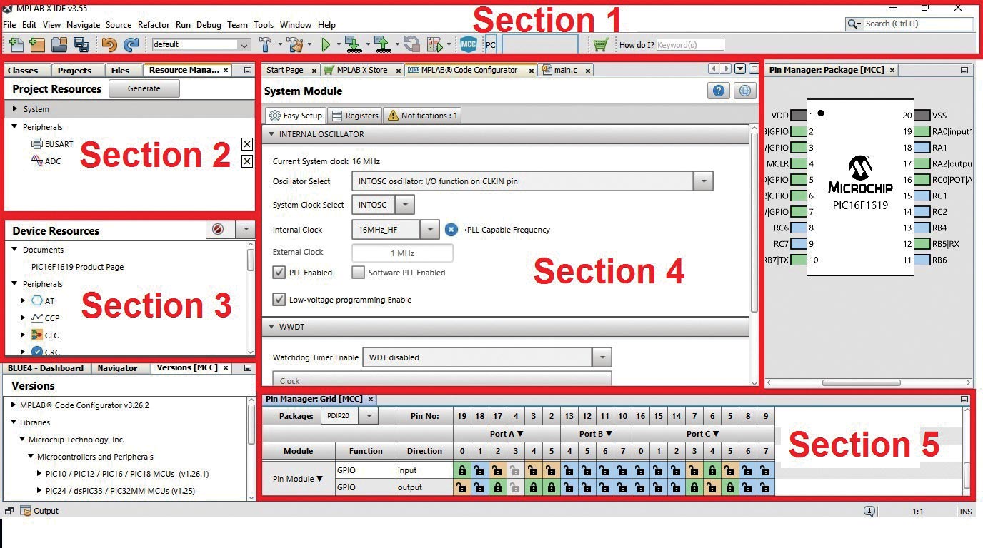
FIGURE 1. MPLABX IDE sections.
Select the PIC16F1619 package type
In the upper left corner of the Pin Manager: Grid [MCC] (Section 5), for Package, select “PDIP20” as shown in Figure 2.
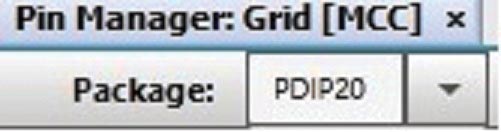
FIGURE 2. IC package type.
Set up the System parameters
In the System Module (Section 4), set System Clock Select to “INTOSC;” for Internal Clock, select “16 MHz_HF.” Also, insure that Low-voltage programming Enable is checked (Figure 3).
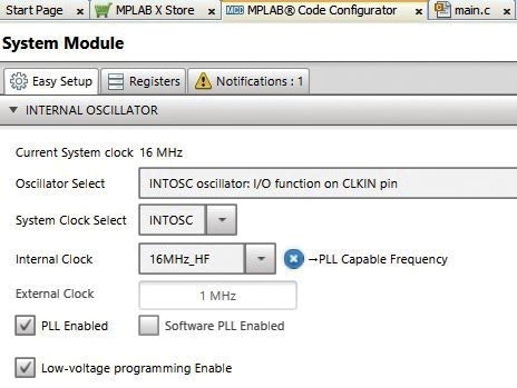
FIGURE 3. System Module setup.
Identify the pins to be used
In the Pin Manager: Grid[MCC] (Section 5) on the GPIO input row, select the “lock” icon for pin 6 (Port C4), pin 16 (Port C0), and pin 19 (Port A0). On the GPIO output row, select the lock icon for pin 2 (Port A5), pin 3 (Port A4), pin 5 (Port C5), pin 7 (Port C3), and pin 17 (Port A2). Note that Figure 4 shows the pin selections for GPIO, as well as the settings for the other device resources to be added in subsequent steps. As we add resources, their pin allowance will appear in the grid.

FIGURE 4. Pin Manager grid.
Configure EUSART pins
In the Device Resources window (Section 3), scroll down the list and expand “EUSART,” then select “EUSART.” The EUSART form will appear in Section 4 and “EUSART” will appear in Project Resources (Section 2). In the Pin Manager: Grid[MCC] window (Figure 4) on the row for EUSART TX, select the lock icon for pin 10 (Port B7); in the row for EUSART RX, select the icon for pin 12 (Port B5).
Configure the USART parameters
On the EUSART screen (Figure 5), check Enable USART, Enable Transmit, Enable USART Interrupts, Enable Continuous Receive, and Redirect STDIO to USART. Set the Baud Rate to “115200,” Transmission Bits to “8,” Reception Bits to “8,” and Clock Polarity to “Non-Inverted.” Check Redirect STDIO to USART; set Software Terminal Buffer Size to “64,” and set Software Receive Buffer Size to “64” as well.
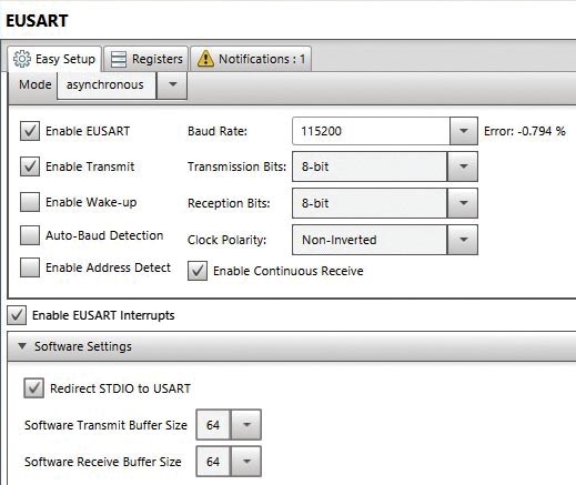
FIGURE 5. EUSART setup.
Configure ADC pins
In the Device Resources window (Section 3), expand ADC and then select “ADC.” The ADC form will appear in Section 4 and “ADC” will appear in Project Resources (Section 2). In the Pin Manager: Grid [MCC] window (Section 5) on the ANx row, select Port C “0” (pin 16) as shown in Figure 4.
Configure ADC parameters
In the ADC form (Figure 6), check Enable ADC, and set Clock to “FOSC/1.6.”
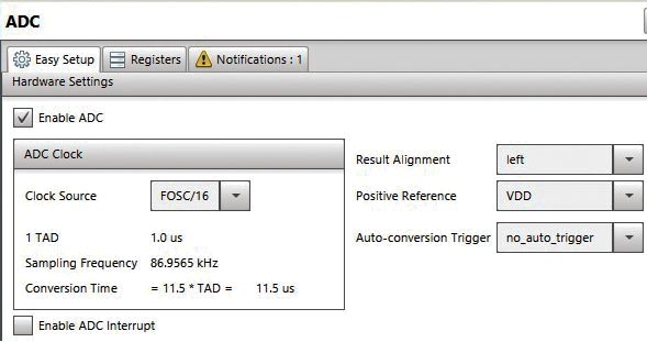
FIGURE 6. ADC setup.
Add custom names to pins
In the Project Resources window (Section 2), select “Pin Module.” The Pin Module form will appear in Section 4. In the Custom Name column, label RA0 as “input1,” RA2 as “outputA,” RA4 as “WAKESW,” RA5 as “outputB,” RC0 as “POT,” RC3 as “WAKEHW,” RC4 as “input2,” and RC5 as “CMD.” Make sure you name them exactly as shown in Figure 7 because the Custom Name is used in the program.
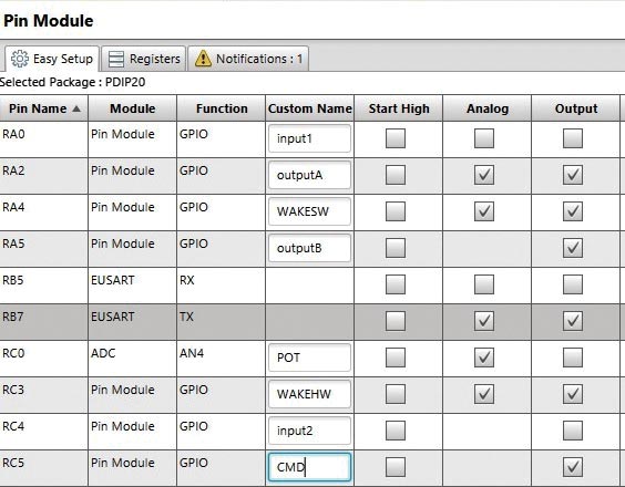
FIGURE 7. Pin module custom names.
Generate code
Select the Generate button located next to Project Resources (Section 2). The MPLABX IDE will then create all the C language code necessary to implement all the settings you previously chose.
Write the program
Above the Project Resources window (Section 2), select the tab labeled Projects. Looking at Figure 8, select the “+” beside the project name (Blue) and then the “+” next to Source. Select main.c. The program listing will appear in the middle window (Section 4).
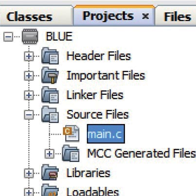
FIGURE 8. Project listing.
Scroll down the program listing to one line under where it says #include “mcc_generated_files/mcc.h” as shown in Figure 9.
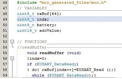
FIGURE 9. Program listing.
This is where you would enter the embedded C program that ties all the pieces together and makes a working project.
The code I wrote to implement the design goals outlined here is contained in the file Blue Source code.txt available at the article link.
To implement my code, erase everything below #include “mcc generated files/mcc.h” and then copy and paste the contents of Blue Source code.txt. You can use Windows Notepad to open and copy the file.
Notice that the program listing has three main sections: Variables, Functions/Subroutines, followed by the main program. The main program also has three parts: SYSTEM_Initialization / interrupts; the RN4020 setup; and the program loop.
Although there are acceptable variations, I recommend sticking with this form and order to minimize confusion. As you will learn when you complete the embedded C programing tutorial, the order and position of the program components matters.
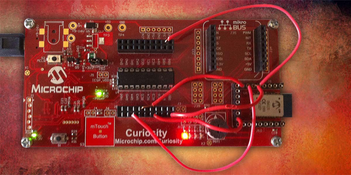
Wire the circuit
Make the connections listed next using jumpers on the Curiosity board shown in Figure 10.
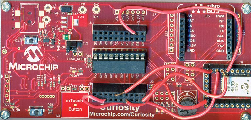
FIGURE 10. Curiosity board wiring.
If you’re using the BLE2 click module, just plug it into the mikroBUS socket; no jumpers are needed.
16F1619 Pin RN4020 Pin
3 ———— jumper ———— 7
5 ———— jumper ———— 8
7 ———— jumper ———— 15
10 ———— jumper ———— 6
12 ———— jumper ———— 5
Build and run the program
Plug the Curiosity board in and select the “Make and Program Device” button on the toolbar (Section 1). It’s the icon with the downward pointing arrow.
Open the “Smart Date” app on your cell phone or tablet
On the opening screen (Figure 11), you should see the name of your project plus the last four digits of the RN4020 serial number. Tap the name of your project.
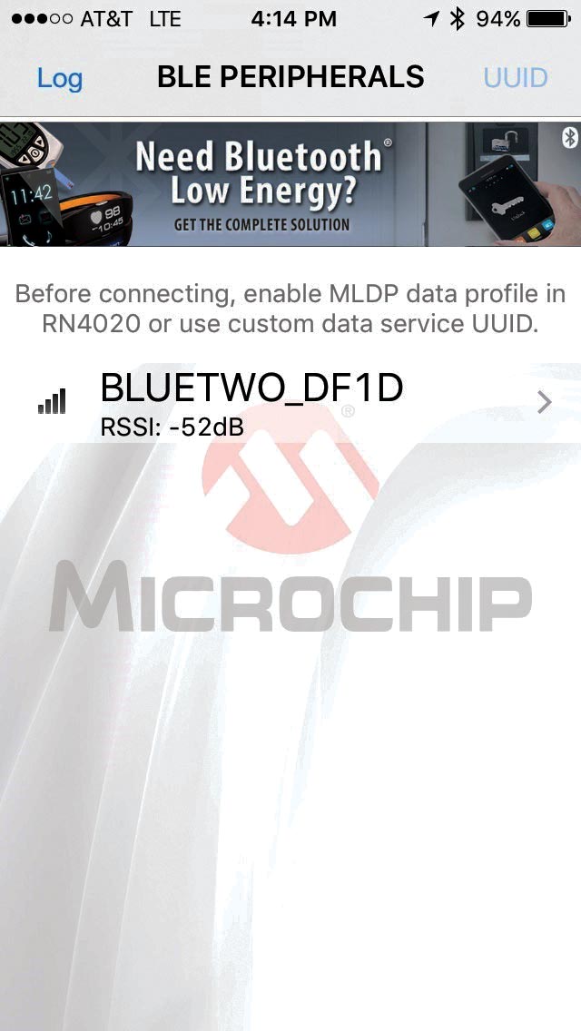
FIGURE 11. iPhone Screen #1.
The data entry form (Figure 12) will open.
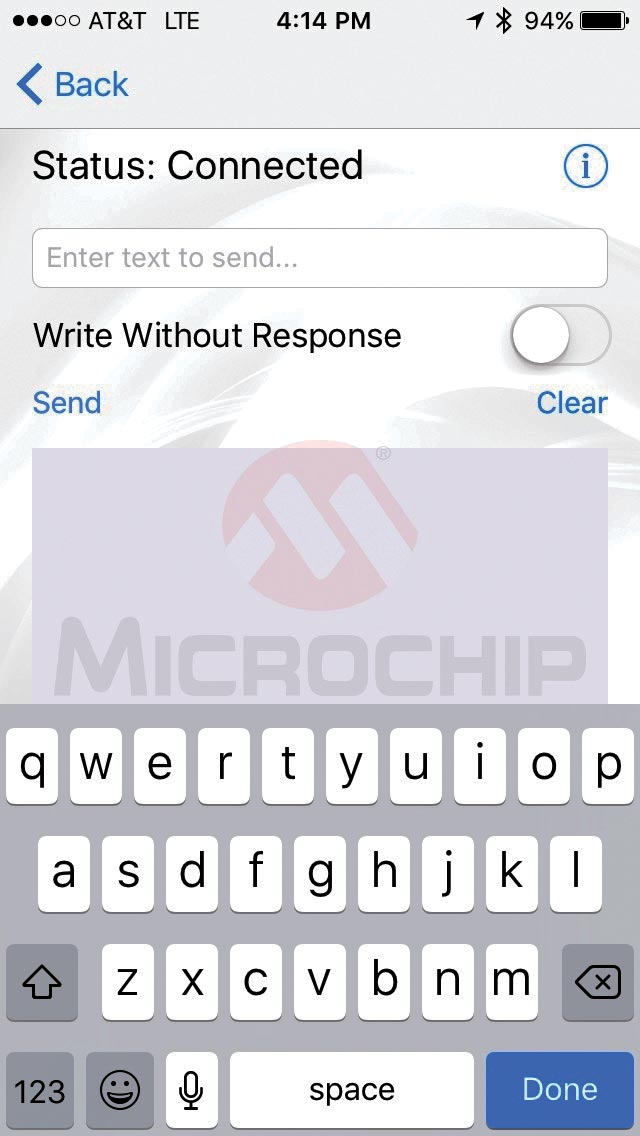
FIGURE 12. iPhone Screen #2.
\Type a “~” in the “Enter text to send” box (marked in Figure 13) and press Send.
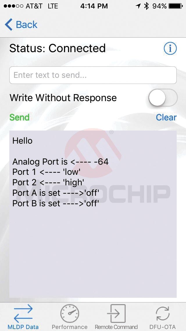
FIGURE 13. iPhone Screen #3.
You’ll get the following response in the lower portion of the form (Figure 13):
Hello<br />
Analog Port is <—— -64<br />
Port 1 <—— “low”<br />
Port 2 <—— “high”<br />
Port A is set ——>”off”<br />
Port B is set ——>”off”
- Enter “A,” tap “send,” and LED D6 will light and the phone app will display Port A is ——>’on.’
- Enter “a,” tap “send,” and LED D6 will turn off and the phone app will display Port A is ——>’off.’
- Enter “B,” tap “send,” and LED D4 will light and the phone app will display Port B is ——>’on.’
- Enter “b,” tap “send,” and LED D4 will turn off and the phone app will display Port B is ——>’off.’
- Enter “1,” tap “send,” and the phone app will display Port 1 <—— ‘low.’
- Enter “2” while pressing switch S1, tap “send,” and the phone app will display Port 1 <—— ‘low.’
- Enter “2,” tap “send,” and the phone app will display Port 2 <—— “high.’
- Enter “3,” tap “send,” and the phone app will display a number representative of the voltage on the center pin of the potentiometer.
That pretty well wraps it up. I have provided a copy of the complete project, as well as a copy of the C code in the downloads below.
Next thing I’m going to do is etch a circuit board so I can move the PIC16F1619 and RN4020 off the development board and get the circuit “out in the “field” for some testing.
After that, maybe I’ll start climbing the curve for iOS application development. NV
Resources
1) Curiosity integrated programmer/debugger (eight-bit)
www.microchip.com/Curiosity
2) RN4020
www.microchipdirect.com/product/rn4020
3) BLE2 click
www.microchipdirect.com/product/TMIK037
4) RN4020 Bluetooth Low Energy User’s Guide
http://ww1.microchip.com/downloads/en/DeviceDoc/70005191B.pdf
5) Microchip C programming tutorial
http://microchipdeveloper.com/tls2101:start
6) Curiosity Development Board User’s Guide
www.microchip.com/developmenttools/productdetails.aspx?partno=dm164137
Additional Tutorial:
Get Started with MPLABX IDE and Microchip Tools
http://microchipdeveloper.com/tls0101:start
Software:
MPLABX IDE and XC16 compiler
http://microchipdeveloper.com/tls0101:start
XC8 compiler
www.microchip.com/mplab/compilers
Downloads
What’s in the zip?
Source Code