Why Use Interrupts?
Interrupts are very powerful tools built into almost every microcontroller. If you write microcontroller code, I can guarantee that they will make your life easier. Once you learn the basics of interrupts, you will find that they work essentially the same on all microcontrollers.
If you’re planning on counting instructions or adding NOPs to your code to get precise timing, you’ll need to learn about interrupts. You’ll find that they not only make it easier to write your code the first time, but — when you have to change the timing of your project — they will really save you time and headaches. Instead of recounting all those instructions, you can just change the interrupt timing by changing a single constant.
If you need to do anything in real time — like controlling a motor or generating and reading communication signals, such as serial streams — interrupts are the way to go. With an interrupt, you will be assured that the timing of your signals will be right. Without consistent timing, you can get jerking in your motors and hard-to-diagnose errors in your communication routines.
Once you’ve become familiar with using interrupts, they will become like the heartbeat of your code, the regular rhythm at the core of your project. You’ll find that they aren’t intimidating and you’ll wonder how you ever wrote microcontroller code without them. You will start designing your project around the interrupt and find that this simplifies the design and makes development faster.
What Is an Interrupt
If you don’t use interrupts, I hope that I’ve motivated you to learn more about them. Let’s start by defining an interrupt. Although there are many different types of interrupts, in this article I will only discuss periodic timer-generated interrupts because I’ve found them to be the most useful; they are also available on almost any microcontroller. Once you’ve learned about timer interrupts, though, it will be easy to extend the basic concepts to other types of interrupts.
In the case of a timer-generated interrupt, the interrupt is an event in the microcontroller that lets you run a short section of your code at a regular interval. For instance, you might set up an interrupt to run at 1 kHz — or 1,000 times per second. In this case, every one thousandth of a second, you will get an interrupt. Like the ticking of a sped-up clock, the interrupts occur on a set schedule and they occur no matter what else is going on in the main body of your microcontroller code.
Each time the interrupt occurs, the microcontroller will run a certain section of the code you’ve loaded into its memory. The code it runs is often referred to as the interrupt service routine (ISR). This is where you do the work of your interrupt. For instance, imagine you are designing a digital clock with a microcontroller and had set it up to have a 100 Hz interrupt. In the ISR code, which would run 100 times each second, you would have a counter that counted up to 100. During each interrupt, you would increment a counter variable and then check to see if that counter had reached 100. If it was 100, you would set it back to 0 and increment the seconds counter on your clock. So, the seconds digit on your clock would increment once every 100 interrupts — exactly once a second. This is a very basic use for an interrupt.
To explore a more complex example, suppose you want to control a motor with a signal generated on one of your microcontroller’s pins. To control the motor’s speed, you could generate a pulse width modulation (PWM) signal using an interrupt. In this case, you would set the interrupt frequency to be equal to the PWM signal frequency, multiplied by the PWM resolution. Then, in each interrupt, your code would decide whether to set the pin high or low to generate the correct PWM duty cycle. I’ll go into this example in more detail below and in the sidebar.
In most applications, you will probably do more than one thing in each interrupt. If your application is a mobile robot, you might generate a PWM signal for each wheel motor, read a few sensor signals, and also keep a timer to control behaviors — all in the same interrupt service routine.
How an Interrupt Works
Microcontrollers have special hardware built into them to generate and handle interrupts. In the case of a timer-generated interrupt, the microcontroller generates an interrupt whenever a specific timer rolls over. Almost all microcontrollers have timers; timers are built-in register variables that are incremented every instruction cycle. Counting the instruction cycles is the same thing as counting the time. Certain instructions take more than one instruction cycle to run, but the instruction cycle time is constant. When a timer reaches its maximum value (255 for an eight-bit timer), it rolls over to a value of 0. If your timer interrupt is enabled, this rollover will generate an interrupt.
For eight-bit microcontrollers, timers that can generate interrupts are usually eight bits or 16 bits, sometimes with prescalers to extend their ranges. A prescaler allows you to get slower interrupt rates with an eight-bit timer, though with less precision. For instance, a prescaler value of 4 tells the microcontroller to increment the timer every fourth instruction cycle instead of every cycle, so that your interrupt frequency is a fourth as fast.
What exactly does it mean to generate an interrupt? To understand this, you need to know what is normally happening when a microcontroller is running. When you program a microcontroller, you place the assembly instructions of your code into sequential program memory addresses. In the simplest case, a microcontroller performs the instructions in its program memory in order. If it just performed the instruction at address location 123, then it will run the instruction at location 124 next.
However, when an interrupt is generated, the microcontroller jumps to a fixed interrupt address instead of going to the next instruction. This special address is sometimes called the interrupt vector and is often toward the beginning of the program memory. This location is where you put the start of your interrupt code. So, generating an interrupt really means making your microcontroller jump to a known address — the start of your interrupt routine.
When the interrupt has done its work, you want the microprocessor to go back to whatever it was doing just before the interrupt happened. There is a special return-from-interrupt instruction that does just this. It signals that the interrupt processing is over and that the microcontroller should go back to where it was prior to the interrupt.
One thing to keep in mind when using an interrupt is that you don’t want to overwrite variables you were using in your main code. This is especially true of the accumulator or working register and any status flags. Some microcontrollers will store some of these important variables for you automatically and restore them at the end of the interrupt. If you are using a compiler, it will usually do this for you if the microcontroller doesn’t, but — if you are writing assembly code directly — you will want to copy the value of the accumulator and any processor flag registers into temporary variables at the start of your ISR and then copy those values back into the registers at the end of the ISR just before the return-from-interrupt instruction.
To recap, the whole process happens as follows: Your microprocessor is performing instructions in the main body of your code. As this is happening, the timer is incrementing. When the timer rolls over from its maximum value to 0, the microcontroller jumps to the interrupt vector address in its program memory. It runs through the instructions of your interrupt routine until it reaches the return-from-interrupt instruction. It then jumps back to wherever it was when the interrupt was generated and keeps running.
Different microcontrollers can also generate interrupts under other specific conditions. For instance, many microcontrollers have special external interrupt pins or pins that can generate interrupts when their state changes. These interrupts operate in much the same way, apart from their triggering. The interrupt service routines will have the same parts, except that they won’t need to reset the timer. When you are using more than one source to generate interrupts, you will need to check which source generated each interrupt at the beginning of your interrupt routine.
The Details — Setting Up and Using Interrupts
There are several things you need to do to get a periodic interrupt running on your microprocessor. I’ll talk about them in general and also give the specifics of getting a periodic interrupt running on the popular Microchip PIC16F84 processor clocked at 10 MHz. The PIC16F84 processor can be purchased from Digi-Key (www.digikey.com).
First, you will need to decide on the frequency of your interrupt. You will choose your interrupt frequency depending on the needs of your application. For our example, we will use the interrupt to generate a 255 step PWM signal on an I/O pin at 200 Hz to control a motor. Since we’ll need an interrupt for each step of the PWM, we’ll need 255 interrupts every 200 Hz, giving us a desired interrupt frequency of 51,000 Hz (200 Hz * 255 = 51,000 Hz).
Next, we need to figure out how many times the timer will increment between interrupts. To do this, we divide the frequency of the timer by our desired interrupt frequency. From the data sheet for the PIC16F84, we know that Timer0 — which is used to generate interrupts — increments once every instruction cycle (not using the prescaler). Also from the data sheet, we know that there is one instruction cycle for every four clock cycles, giving us an instruction cycle frequency of 2.5 MHz (10 MHz / 4 = 2.5 MHz). We now divide this by our desired interrupt frequency of 51,000 and we get 49.02 (2,500,000 / 51,000 = 49.02). Since we need an integer number of timer increments per interrupt, we round this to 49. So, the timer will increment 49 times from one interrupt to the next.
Now, the next fact we need to know is that Timer0 causes an interrupt when it rolls over, when its value goes from 255 to 0 (255 is the maximum value for an eight-bit timer). From the last step in our calculation, we know that we want 49 increments between interrupts to get our desired frequency. So, if we subtract 49 from the timer’s value during our interrupt, we know that the next interrupt will occur 49 cycles later than this one. This is how we set the interrupt frequency. If we don’t change the timer’s value during the interrupt, we will instead get interrupts every 256 cycles when the timer naturally rolls over.
Another thing to keep in mind is that you might have to adjust the value you subtract from the timer because you lose a few cycles doing the subtraction. This is because the timer value will continue to increment while you are doing the subtraction. For instance, if reading the timer, subtracting, and writing the timer again takes three cycles, you will want to actually subtract 46 from the timer instead of 49. Otherwise, your interrupt frequency will be slightly off.
An alternate way to set the interrupt frequency is to load a constant value into the timer at the beginning of each interrupt. This method uses fewer instructions to set the timer, but is less accurate because it doesn’t take into account the interrupt latency. The interrupt latency is the few instruction cycles it takes between the timer rolling over and the first instruction of your interrupt service routine. The interrupt latency varies for different microcontrollers and can also vary slightly from interrupt to interrupt, depending on the microcontroller. When the latency varies slightly, so will your interrupt frequency.
If we were to use this method in our example, what value would we need to load into the timer at the beginning of our interrupt so that — 49 cycles later — the timer will roll over? We subtract 49 from 256 (the timer rolls over one cycle after it reaches 255) and get an answer of 207. So, if we load a value of 207 into the timer at the beginning of our interrupt, the next interrupt will happen when the timer rolls over 49 cycles later. If you really need to make your interrupt routine short, this can be a good alternate way to set the interrupt rate.
Microcontrollers signal that an interrupt condition has been reached by setting a flag — a bit in one of the system registers. For our timer interrupt, this flag is set when the timer rolls over. If that interrupt is enabled, this will trigger an actual interrupt. In most microcontrollers, you will need to clear this flag by hand in your interrupt routine or you will keep getting the same interrupt over and over. For our Timer0 interrupt in the PIC16F84, this means clearing the T0IF bit with a BCF instruction.
The next step is writing your actual interrupt service routine. You already know a few things that need to appear in the routine. At the beginning, you need to save the state of important registers, clear the flag, and subtract your interrupt cycle value from the timer. At the end of the interrupt, you need to restore the register values you saved and then have a return-from-interrupt instruction. The return-from-interrupt instruction is always the last instruction of your interrupt service routine.
Here are the tasks that you will need to do in each of your interrupt service routines (See the interrupt service routine in the sidebar for a specific example.):
- Save the values of the system registers you use in the interrupt.
- Subtract from the timer the “timer increments per interrupt” value you calculated.
- Clear the interrupt flag.
- Write the body of your interrupt. In our example, this is the PWM generation code.
- Restore the system register values that you saved.
- End your interrupt routine with the return-from-interrupt instruction.
The final step to getting your interrupt running is to set the hardware bits that enable the interrupt and the timer. Most microcontrollers have both a global interrupt enable bit and bits that enable each individual type of interrupt. When the global interrupt enable bit is not set, all interrupts in the microcontroller are disabled. For an interrupt to be enabled, both the global and the individual interrupt enable bits must be set.
In the PIC16F84, you can set these bits directly using the BSF instruction. The global interrupt enable bit is named GIE and the Timer0 interrupt enable bit is named T0IE. You also need to set up and enable the timer so that it starts incrementing every instruction cycle. In my example, I set the PSA bit to have no prescaler and set the T0CS bit to start the timer incrementing. You only need to set these values once, unless you want to turn the interrupts on and off. I usually set them in an initialization section at the beginning of my main body of code.
If you are writing your interrupt routines in a C compiler, the compiler may take care of some of these details for you. It will probably enable you to write the body of your interrupt routine in a special interrupt function. From this function, it will generate the assembly code and place the routine at the correct interrupt vector address and also save the state variables for you. Some microcontrollers also automatically save the important registers for you whenever an interrupt occurs and then restore them when the interrupt is over. Refer to your microcontroller’s data sheet to see if it saves any register values automatically.
One general rule to remember is to keep your interrupt code short. This is a solid principle, but it doesn’t mean that you can’t do any processing in your interrupt. The thing you want to absolutely avoid is for the next interrupt to occur when the last one is still running. In our example, we generate an interrupt every 49 instruction cycles. So, it’s clear to see that — if our interrupt takes more than 49 instructions to run — the next interrupt will want to run before the current one is over. This is a problem and it means that the main body of your code will never get to run.
The longer your interrupt routine, the less processing time is left for your main code. Because of branches in your code, the number of instruction cycles it takes to run can vary from interrupt to interrupt. In practice, I’ve found that interrupt routines can take up 50% of the time between interrupts without causing problems. In our example, this would mean an interrupt routine that runs in 24 instructions or less. Overall, shorter is usually better.
How to Know it’s Working
Now that you’re done writing your interrupt code, how do you confirm that you did everything right? It is really easy to debug an interrupt if you have an oscilloscope. Add two more instructions to the main body of your interrupt routine. At the very beginning of the body, set one of your microcontroller pins high. On the PIC16F84, you can use the BSF and BCF instructions to set just one pin at a time. At the end of the interrupt body, set the same pin low. Then, run your application and hook an oscilloscope to the pin. You should see an oscilloscope trace like the one shown in Figure 1.
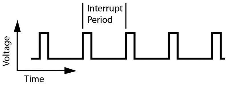
FIGURE 1. An oscilloscope trace of a typical interrupt.
The time from the beginning of one pulse to the next is the period of your interrupt. The width of each pulse divided by the period gives you the approximate percentage of processing time that your interrupt is using. Keep in mind that this doesn’t take into account the latency or the set-up and ending instructions. The real time taken by the interrupt is a bit more.
If you don’t have an oscilloscope, there are still easy ways to check that your interrupts are running and at the right frequency. A good debugging tool is an LED hooked up to one of your microcontroller pins. If you did what I explained above, the LED would blink, but it would blink so fast that you would never be able to see it. So, you need to slow down the blinking by incrementing a counter. In our example, the interrupt rate is 51,000 Hz. If we divide the frequency down by 51,000, our LED will blink on for a second and then off for a second. We can use two cascading eight-bit timers or one 16-bit timer to accomplish this. For the eight-bit case, you would increment your first timer in each interrupt. Whenever this timer rolled over (from 255 to 0), you would increment your second timer. When the second timer reached 200, you would set it back to 0 and flip the state of your pin from high to low or low to high. In this way, you can confirm that your interrupt is running and running at the right rate because the LED is blinking on for a second and then off for a second.
Once you have your first interrupt running, you will know all the basics of using interrupts. These same methods will work on any microcontroller, with slight changes to handle the specifics of the hardware. As you become comfortable using interrupts, you will start to find more uses for them in all of your microcontroller projects. NV
An Example Interrupt — Generating PWM on a PIC16F84
The interrupt service routine code shown below generates a PWM signal on pin 0 of PORTB with the duty cycle set by the variable pwm_duty. A value of 0 specifies 0% PWM and a value of 255 specifies 100% PWM. Intermediate values scale linearly. Figure 2 shows what an oscilloscope trace looks like attached to the PWM pin with a pwm_duty value of 178. The SWAPF instruction is used to store the STATUS and W registers because it doesn’t affect the STATUS flags that we are trying to save.
ORG 0x04 ; Interrupt vector location
int0:
MOVWF w_temp ; Save the W register
SWAPF STATUS,0
MOVWF status_temp ; Save the STATUS register
BCF INTCON,T0IF ; Clear interrupt flag
MOVLW D’46’
SUBWF TMR0,1 ; Subtract 46 from the timer
pwm0:
INCF pwm_phase,1 ; Increment the phase
MOVLW D’255’
SUBWF pwm_phase,0
BTFSS STATUS,C ; If phase >= 255, reset
GOTO pwm1
CLRF pwm_phase ; Reset phase
MOVF pwm_duty,1 ; If it’s the PWM period start
BTFSS STATUS,Z ; Check if duty cycle is zero
BSF PORTB,0 ; If not zero, start PWM pulse
GOTO pwmEnd
pwm1:
MOVF pwm_duty,0
SUBWF pwm_phase,0 ; Subtract to compare
BTFSC STATUS,C
BCF PORTB,0 ; If phase >= duty, end PWM pulse
pwmEnd:
SWAPF status_temp,0
MOVWF STATUS ; Restore the STATUS register
SWAPF w_temp,1
SWAPF w_temp,0 ; Restore the W register
RETFIE ; Return from the interrupt
intEnd:
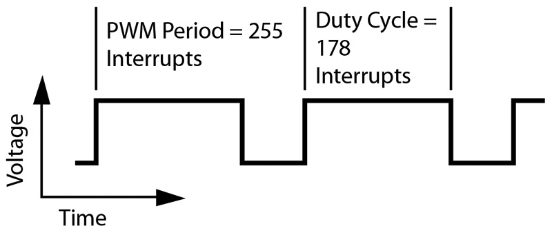
FIGURE 2. An oscilloscope trace of PWM generation using an interrupt with a 70% duty cycle.