Editor's Note - This is Part 1 of a two part article. Part 2 appears in the April 2016 Print Edition of Nuts & Volts.
As I mentioned at the end of the February Primer, we're now going to turn our attention to using a thermocouple sensor and a solid-state relay (SSR) to monitor and control the temperature of an electric smoker. This time, we'll focus on simply monitoring the temperature, and then we'll control it as well. Even if you have no need to control a smoker of any sort, being able to interface a PICAXE processor with an SSR makes a variety of electrical control projects possible. For example, the techniques we're going to explore could be used to control the speed of a fan or a motor to accomplish a variety of home control tasks. If you share my interest in applying the principles of digital control to food preparation and cooking, you've probably already been thinking about the possibility of an inexpensive PICAXE-based sous vide controller. That one's on my to-do list as well, but for now, we'll simply focus on an electric smoker.
SSR Basics
Any discussion of SSRs needs to begin with a few words of warning. As you undoubtedly know, 120 VAC can be lethal. Therefore, if you decide to experiment with an SSR, it's important to be aware of a couple of basic safety precautions:
- Never work on a 120 VAC circuit without first disconnecting it from the current source.
- Make certain that all 120 VAC connections are completely insulated.
- Thoroughly test your completed project to be sure it's working correctly before leaving it powered on and unattended.
All electric smokers that I have seen are powered by 120 VAC, so the following discussion will focus on SSRs that are designed to control an AC load. (If you're planning a project that involves controlling a DC device, you will need to do some research to find a suitable DC SSR.) AC SSRs with current capabilities ranging from 10A to 40A or more are widely available on Amazon, eBay, and elsewhere.
However, many of the available devices are apparently counterfeit, and may pose serious safety issues. Before you choose a specific device, you may want to read a UL notification about counterfeit versions of one of the more popular SSR brands. (A pdf version of that notification is included in the downloads here.) If you want to minimize the chance of getting a counterfeit SSR, you might want to purchase one from a reliable vendor. One possibility is included in the "Sources" sidebar at the end.
Most currently available SSRs are optically isolated devices, which means there's no direct electrical connection between the low voltage DC control circuitry and the AC device that's being controlled. In addition, most modern AC SSRs (including the one that I purchased) have what's called a "zero-crossing detection" feature which ensures that power to an AC load is always applied and/or removed at a point when the AC voltage changes from positive to negative (or vice versa), in order to avoid the electrical noise created by excessive current spikes.
In other words, if a program raises or lowers the DC input to the SSR at any non-zero point in the AC power wave, the load will not turn on (or off) until the AC voltage crosses zero. So, the current surge is also effectively zero.
The majority of SSRs can operate with DC inputs between 4V and 32V, and only require a DC current of 8 mA to 15 mA. Of course, you should always check the specifications of any SSR you're considering to be sure it will work correctly with a 5V DC input, and require no more than the PICAXE maximum output current of 20mA.
Finally, all SSRs can produce a significant amount of heat — especially in high current situations, so a good heatsink is an absolute necessity. Many SSRs are sold with a heatsink already attached, so you may want to consider that factor as well. (See the Sources sidebar again for one possibility.)
Experiment 1: Testing an SSR
After reading the UL notification and doing a fair amount of additional online research, I purchased a (hopefully genuine) Fotek SSR-25 DA device and a heatsink on eBay (refer to Figures 1 and 2).
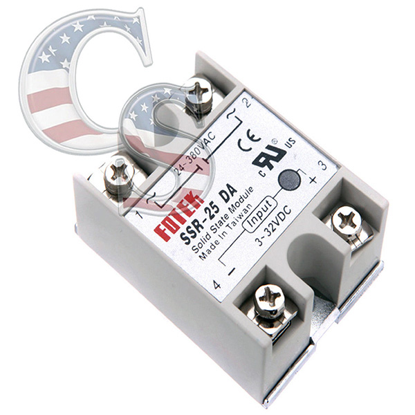
FIGURE 1. SSR-25 DA.
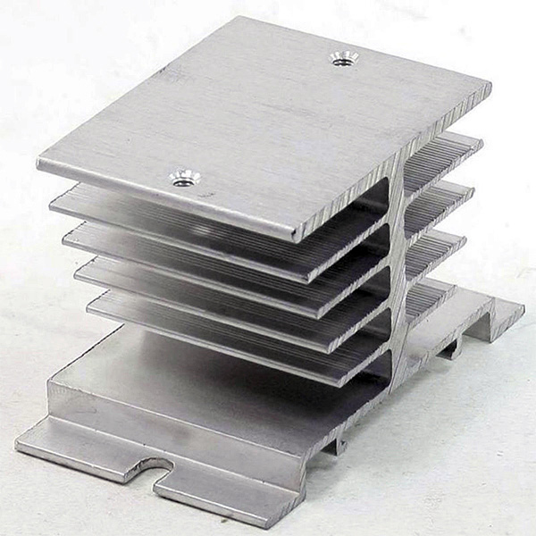
FIGURE 2. Heatsink for SSR.
I made the necessary connections by mounting the heatsink on the side of a plastic electrical box and including a double 20A electrical outlet, so that I can easily plug in whatever AC device I want to control. In retrospect, making the box assembly was more trouble than it was worth. I plan to purchase a second SSR for another project and to directly connect a heavy duty extension cord to the SSR. That would be much easier to do, and should work just as well as my first approach.
Figure 3 is a photo of the test arrangement that I used for this experiment. In the photo, the bit of hardware sticking up through the heatsink is one end of a hex bolt that I added because the weight of the heatsink was tipping the assembly to the left; the bolt prevents that from happening. Also, note the black electrical tape around the SSR near the left edge of the photo. It insulates the AC connections to the SSR to avoid any possibility of electrical shocks.
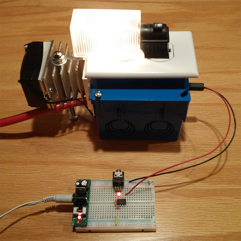
FIGURE 3. Testing the SSR.
To test the SSR, I wrote a simple 08M2 "Hello World" program that simultaneously toggles pin C.0 (which is connected to the LED) and pin C.2 (which is connected to the SSR DC input). The experiment functions flawlessly. The real time state of the AC night light (on/off) perfectly mirrors that of the LED.
Some Background Information
My electric smoker is located in the furnace room in the basement of my house, and my various computers are about 20 feet away in my basement "playroom." Because I knew that developing this project would involve many cycles of testing and refining the software, I decided to set up a wired connection between my main computer and the smoker so I could do all the necessary work without running back and forth between my desk and the smoker. I also knew that the 08M2 processor couldn't be located 20 feet from the thermocouple sensor because the resistance of a 20 foot wire would definitely reduce the accuracy of the temperature measurements. As a result, I decided to place the entire 08M2 circuit (including the thermocouple interface) right next to the smoker and the SSR assembly in the furnace room.
I also wanted the power supply for the 08M2 circuit to be located next to my computer, so that I would be able to cycle the power off and on as necessary, without getting up from my computer chair and walking to (and back from) the furnace room. The first question I had about this arrangement is whether I could reliably program a PICAXE processor via a 20 foot cable.
To find out, I needed a four-wire cable for the necessary ground, +5V, Serial In, and Serial Out connections. I spent a fair amount of time looking through my many boxes and storage bins for a suitable cable, but couldn't find one long enough. However, I did find a large box of CAT-5 cables, which reminded me that I also have many CAT-5 cables snaked through the walls of my house.
Before the advent of Wi-Fi, all these cables connected various locations in the house to a 16-port switch in the furnace room. Now, several of the wires have been disconnected and replaced with wireless connections, so I decided to use an existing 25 foot CAT-5 cable that runs between my computer desk and the furnace room to test the "remote" connection for my smoker control project. I also realized that an important side benefit of this approach (if it worked reliably) would be that all the other unused CAT-5 cables still running through the walls of my house would be available for various home control projects that I might want to implement in the future.
Unfortunately, as you probably know, the two rows of pins in an RJ45 connecter are offset by 0.5", so those connectors aren't very suitable for use with either breadboards or stripboards. My original intention was to use an RJ45 breakout board at each end of the CAT-5 cable because that approach would facilitate connections to breadboards as well as stripboards (see Figure 4 and the Sources sidebar for one possibility.)
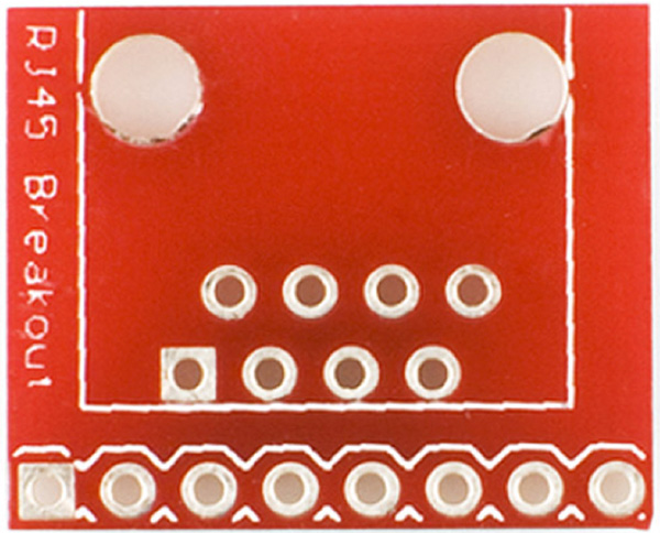
FIGURE 4. RJ45 breakout board.
However, at some point I noticed something interesting about two of the RJ45 connectors that I had on hand (refer to Figure 5, which shows a photo of the backs of both connectors).
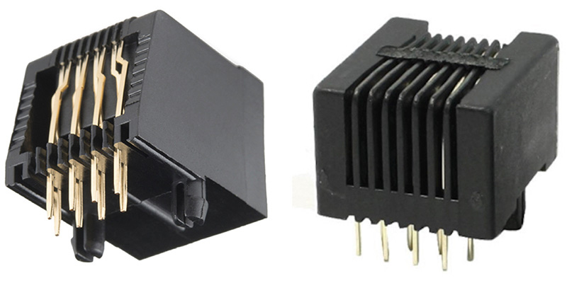
FIGURE 5. Two RJ45 connectors.
As you can see, the connector on the right has a solid section of plastic that covers part of the length of all eight pins along the bottom portion of the back of the connector. On the other hand, on the connector on the left side of the photo, both rows of pins have been press-fitted into thin slots in the plastic near the bottom of the connector (see Figure 6 for a better view of the slots). If you have needle-nose pliers with very thin points, it's easy to grab each pin (just above the slot in the plastic) in the row of four pins closer to the back of the connector, and pull the pin out of its slot.
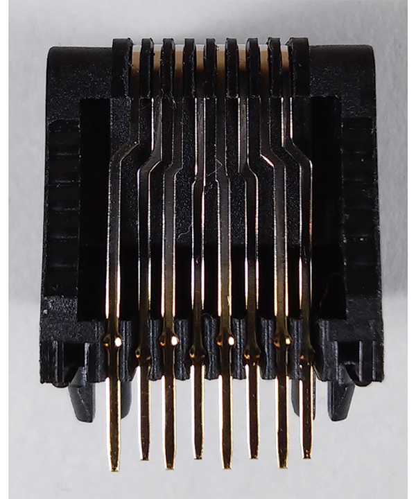
FIGURE 6. "Slotted" RJ45 connector (back view).
If the points of your pliers aren't thin enough to do that, it's also possible to use diagonal cutters to snip off some of the plastic along the back edge of the bottom of the connector. Either way, you end up with a connector that looks something like the bottom-view photo shown in Figure 7. (In the photo, it is also easier to see how the four pins in the back row were originally press-fitted into the shorter slots.)
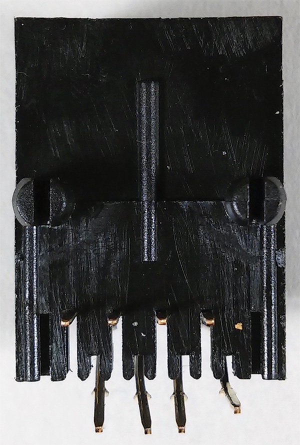
FIGURE 7. "Slotted" RJ45 connector with pins pulled out.
When the four pins in the back row have been removed from the slots, it's a simple matter to move them slightly so they line up with the four pins in the front row, and insert them into the same stripboard traces as the four corresponding pins in the front row. Therefore, it's easy to construct a simple stripboard adapter that converts an RJ45 connector to a "breadboard friendly" four-wire interface. (If you have trouble locating a suitable RJ45 connector for this modification, see the Sources again.)
Figure 8 is a top-view photo of one that I made in less than 15 minutes. In the photo, the four-pin male header at the top edge of the stripboard is one of our longer "reverse mounted" headers, so it provides sufficient pin length to be inserted into a breadboard or soldered into a stripboard.
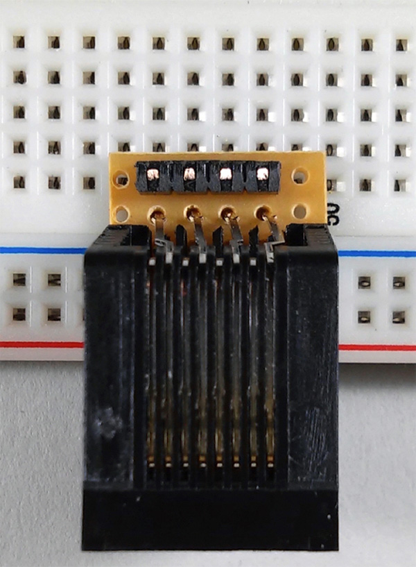
FIGURE 8. RJ45 stripboard adapter (top view).
Figure 9 presents a photo of the bottom view of the same stripboard adapter. In that photo, you can see that it's not necessary to remove the two round plastic protrusions on the RJ45 connector because the stripboard doesn't extend past them. You can also see that the RJ45's two four-pin rows end up to be 0.2" apart rather than the 0.1" spacing that they had on the original connector.

FIGURE 9. RJ45 stripboard adapter (bottom view).
If you prefer, you could press the four pins back into the deeper slots a bit before soldering the connector to the stripboard. That way, the two rows would still be 0.1" apart. Of course, either way, you end up with a four-wire connection, not an eight-wire connection. If your project requires more than four pins, a standard RJ45 breakout board would be necessary.
Experiment 2: Testing the "Remote" Programming Connection
For this experiment, I needed two simple breadboard circuits. Next to my computer, I set up a breadboard with a +5V power supply, a programming adapter, and the RJ45 stripboard adapter we just discussed, into which I inserted one end of a 25 foot CAT-5 cable (refer to Figure 10).
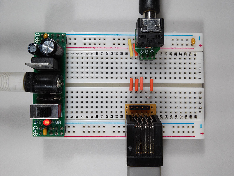
FIGURE 10. Computer breadboard with RJ45 stripboard adapter.
Counting from left to right, the four pins of the stripboard adapter are connected as follows:
- Pin 1 (Wires 1 and 2): Ground
- Pin 2 (Wires 3 and 4): +5V
- Pin 3 (Wires 5 and 6): Serial In
- Pin 4 (Wires 7 and 8): Serial Out
If you would rather not construct the four-wire RJ45 stripboard adapter, you could use a standard RJ45 breakout board instead. Figure 11 is a photo of the same interface circuit that's shown in Figure 10, but this time the four un-insulated jumpers (directly above the breakout board in the photo) combine each adjacent pair of wires in the same manner as the stripboard adapter.
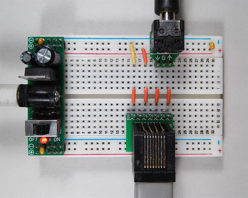
FIGURE 11. Computer breadboard with RJ45 breakout board.
At the other end of the CAT-5 cable (next to the smoker in the furnace room), I set up a simple 08M2 "Hello World" breadboard with an LED on pin C.0, and made the appropriate connections from a second RJ45 connector (mounted on another stripboard adapter) to the 08M2 processor. I ran through several cycles of powering the circuit off, changing the LED blink rate in the program, and then re-powering and re-programming the 08M2. Everything worked perfectly, so I was ready to move on.
Experiment 3: Monitoring the Temperature of an Electric Smoker
Before beginning work on the smoker control project, I decided to first experiment with a simpler monitoring circuit, so that I would be sure that the data being sent from the remote 08M2 circuit in the final control project would be reliably received in the terminal window on my Mac. This experiment turned out to be fairly similar to the data-logging experiment we conducted in previous installments of the Primer.
However, the required hardware is much simpler than that of our earlier experiment, for two reasons: First, we don't need the FRAM board we used last time because we now have a wired connection between the data logger circuit and the Mac (or PC); and second, we also don't need a display at the smoker end of the cable because the real time data will be visible in the terminal window. The schematic for this experiment is presented in Figure 12, and a photo of my breadboard setup is shown in Figure 13.

FIGURE 12. Schematic for Experiment 3.
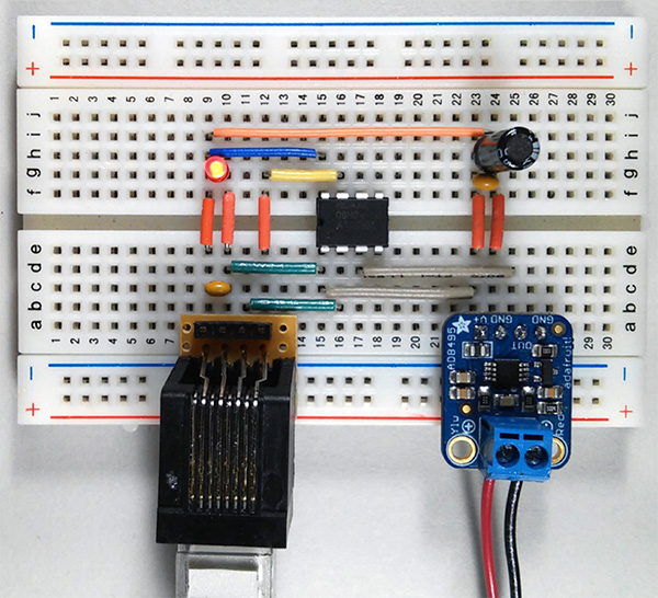
FIGURE 13. Breadboard setup for Experiment 3.
Figure 14 presents the setup I used for this experiment.
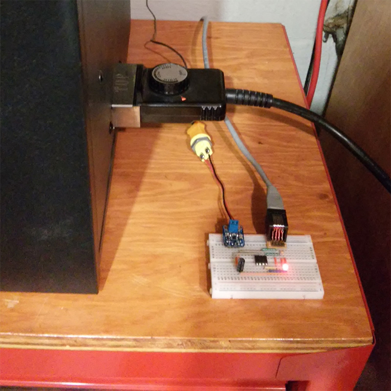
FIGURE 14. Complete setup for Experiment 3.
I placed the completed breadboard (Figure 13) next to my smoker in the furnace room, and connected the CAT-5 cable to the RJ45 connector on the breadboard. In the back of the smoker (near the top), I drilled a hole just large enough to accommodate the thermocouple probe, and then inserted the probe all the way into the smoker. I inserted the other end of the thermocouple sensor cable into the same female thermocouple connector we used in the previous Primer (refer to Sources) and inserted its two wires into the appropriate positions on the AD8495 breakout board. Finally, at my computer desk, I still had the same breadboard setup we just used in Experiment 2 (Figure 10).
As usual, the software for this experiment (SmokerMonitor.bas) is available here. It's very similar to the FRAMdataLogger.bas program we used in the February Primer, but it's a little simpler because we can eliminate two subroutines: the displayTempF subroutine, which we used to display the data on the LED; and the storeData subroutine, which we used to store the time and temperature data in the FRAM.
On the other hand, there is a fundamental difference between the FRAMdataLogger.bas and SmokerMonitor.bas programs. In the February Primer, we were logging the data at one minute intervals which worked well for the purpose of monitoring the BBQ temperature. However, now that our ultimate goal is to control the temperature (as well as monitor it), we'll need to make our heat adjustments much more frequently than once per minute because frequent adjustments result in better temperature control.
As we'll see in the April installment of the Primer, I decided to adjust the level of heat in the smoker at one second intervals, and to log the data at 12 second intervals. I also decided to take the same approach in the SmokerMonitor.bas program, even though it isn't at all necessary when simply monitoring the smoker temperature because it's less confusing than using two different approaches.
Now would be a good time to take a look at the SmokerMonitor.bas program. If you compare it with the FRAMdataLogger.bas program from February, you'll see how similar they are. In fact, there are only three points I need to clarify:
- As you can see in the constant declarations near the top of the program listing,
C.0. is declared as the TxD pin for data transmission to the terminal window. Usually, the sertxd command is used for serial output on pin C.0. However, the program is running at 16 MHz, so the sertxd command would be fixed at 19200 baud. I was concerned that might be too fast for reliable serial transmission over a 25 foot cable, so I decided to use the serout command instead and slow the baud rate down to N4800_16 to make sure the data transmission would be 100% reliable, which has been the case throughout all my testing in Experiment 3.
- In the earlier
FRAMdataLogger.bas program, we used a do/loop until structure, which contained a pause of 25 mS to allow a full two seconds to elapse before repeating the main do/loop. In the SmokerMonitor.bas program, we're again using the same structure and a pause of 25 mS would certainly work here as well. However, in preparation for the more stringent timing requirements that will be needed (when we actually control the smoker temperature), I decided to use an empty do/loop until structure (at the end of the main do/loop) for the monitoring program, as well. Because the do/loop until doesn't contain any other commands, it executes extremely fast. So, the one second timing of the main do/loop is much more accurate.
- In the logData subroutine, the
minute = time / 6 statement requires a brief explanation. If you look back at the main do/loop, you'll see that the logData subroutine is called in every 12 iterations of the main do/loop, i.e., every 12 seconds. In other words, each time the logData subroutine is called, the time variable is an exact multiple of 12. For example, when 48 seconds have elapsed, the logData subroutine is called and time = 48, so minute = 48 /6 = 8. However, the program keeps track of time in tenths of a minute, so the first serout command in the <tt>logData </tt>subroutine formats the value of 8 as "0.8" and sends it to the terminal window because 48 seconds equals 0.8 minutes.
The control dial on my smoker doesn't include any temperature markings at all. It can just be rotated between an "off" position at one extreme, a "high" position at the other extreme, or anywhere in a "Medium" range in the middle of the dial's rotation. The control unit also includes a small neon indicator that is only lit when heat is being applied to the smoker. I assume this unit is essentially the same as what's used for electric frying pans: Turning the dial adjusts the distance between a fixed contact and a mechanical bimetal temperature sensor that bends in proportion to the real time temperature.
I was curious to find out how well the smoker could maintain a fixed temperature without the help of a PICAXE based control circuit. So, for this experiment, I set the dial to the middle of its "Medium" range and downloaded the SmokerMonitor.bas program to the 08M2 circuit in the furnace room. I allowed the program to run for more than 80 minutes, and then saved the accumulated data that was displayed in the terminal window to a file on my desktop.
The PICAXE Editor automatically assigned a "txt" extension to the saved file, so I changed that extension to "csv" (comma separated values). On my Mac, double-clicking a "csv" file automatically opens the file in a Microsoft Excel spreadsheet. In Excel, I selected all the data values including the two column headers ("Time" and "Temp"), and then selected Charts >> Scatter>> Smooth Lined Scatter from the drop-down tabs near the top of the Excel window. The resulting chart (Figure 15) reveals a problem with the smoker's built-in temperature control.
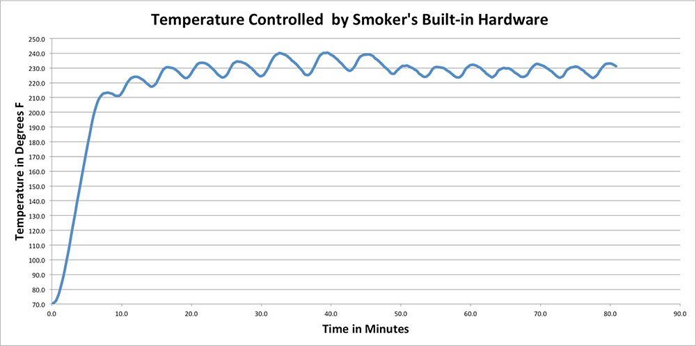
FIGURE 15. Excel chart of Experiment 3 results.
From about 50 minutes to 80 minutes, the smoker temperature averaged 228 degrees, with a reasonable magnitude of oscillation during that time. However, it took 50 minutes before the temperature oscillations stabilized around that average.
As we'll see in the April (Print Edition) installment of the Primer, our results will be greatly improved by the addition of the 08M2 hardware and a software control program. Our smoker control project will be able to stabilize the temperature within 10 to 15 minutes of start-up, which is a significant improvement. In addition, we'll also solve an even greater problem. In Experiment 3, I wasn't able to choose the temperature I wanted; all I could choose was a "medium" temperature. In the April Primer, we'll be able to specify the exact temperature we want the smoker to maintain. NV
SOURCES
| |
Product # |
Source |
| K-Type Thermocouple Amplifier Breakout Board (AD8495) |
1778 |
adafruit.com |
| K-Type thermocouple probe for Smoker or Oven (max. 900°F) |
TC-K3MM |
auberins.com |
| Thermocouple connectors, Male and Female |
Connectors |
auberins.com |
| Solid State Relay, AC Load, 25 A, Zero-Crossing |
MGR-1D4825 |
auberins.com |
| Heatsink for 25A SSR |
HS25ET |
auberins.com |
| RJ45 Breakout Board |
808-007 |
sparkfun.com |
| RJ45 Connector |
PRT-00643 |
sparkfun.com |
Downloads
What’s in the zip?
SmokerMonitor.bas
UL warning PDF