One of the most impressive additions you can make to an animatronic character is to add the ability for it to speak. Though this task can be accomplished in any number of ways, in this article we’re going to take an in-depth look at one of the most exciting new systems available today.
Hey! I’m Talkin’ Here!
The talking skull has been done to death (heh!), but seriously, what graveyard or spooky fall festival would be complete without a cowled crypt keeper entertaining the crowd with giggles and silly banter?
There are a ton of choices when it comes to talking skull setups. There are entry level skull systems that can be had for under $50 and then there are high-end commercial systems that start at $800 and go up from there. Or, if DIY is your style, the Internet is loaded with different self-serve skull systems.
So, what can we do different that will make our skull stand head and shoulders above the rest in power, performance, and features?
Introducing the Wee Little Talker
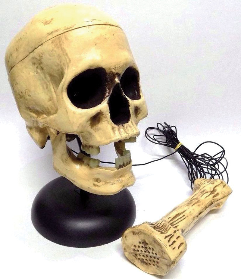
Talking skulls have come a long way since the original “Boris” units sold by Gemmy in the late 2000s (Figure 1).
FIGURE 1. Boris, the Talking Skull.
These original skulls used a rather primitive system consisting of a small DC motor to wind up a string that, in turn, pulled open the jaw. To drive the motor, you spoke into a microphone that drove a small audio amplifier.
The output of the audio amplifier was then rectified and filtered to drive the motor to pull the jaw open until it reached a “stall” at the end of travel. When the audio level dropped, a spring would pull the jaw back to its default “closed” position and would pull the string back by unwinding it from the motor. This simplistic system provided fairly good audio/jaw sync as the amplitude of the audio created a proportional jaw movement.
The next generation of talking skulls used RC receivers and servo motors to “puppet” the jaw. This allowed very precise control over jaw position, but it also required a relatively talented operator and quite a bit of rehearsal in order to put on a good performance (Figure 2).
FIGURE 2. Talking skull with servo drive and RC receiver.
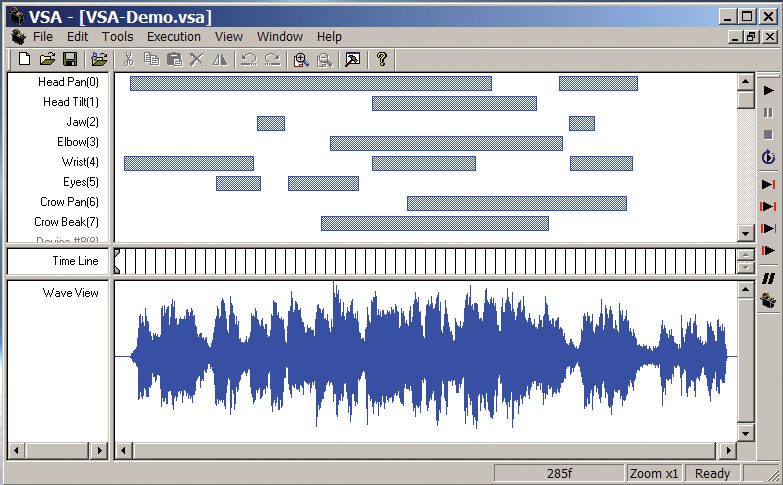
Another step forward came as folks noticed that servo motors lent themselves to programming via computer. With the addition of a serial servo control board, a computer, and some homebrew software (or $100 or more to purchase a commercial program!), you could record servo positions and synchronize them to sound files. This approach provided excellent results with pin-point accuracy for jaw sync, but it was VERY time intensive. Plus, once you had a show programmed, any change in the audio usually required you to re-program the entire sequence from scratch (Figure 3).
FIGURE 3. Visual Servo Automation (VSA) software from Brookshire Software.
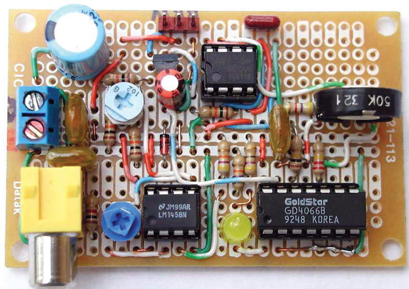
The next iteration of servo/jaw sync was introduced by “Scary” Terry Simmons (see Resources). This clever little analog circuit used a threshold detection system to move the jaw (Figure 4).
FIGURE 4. Original Scary Terry talking skull control board.
Essentially, if the audio input signal was louder than a set threshold, the servo motor was driven towards the fully open position. If the audio signal dropped below that threshold, the servo would seek back to the jaw closed position (see a detailed discussion of this circuit in the September 2008 issue of Nuts & Volts). Carefully adjusting a number of controls on the board sometimes allowed the circuit to perform surprisingly well, although quite a bit of “tweaking” was often required to get optimum results.
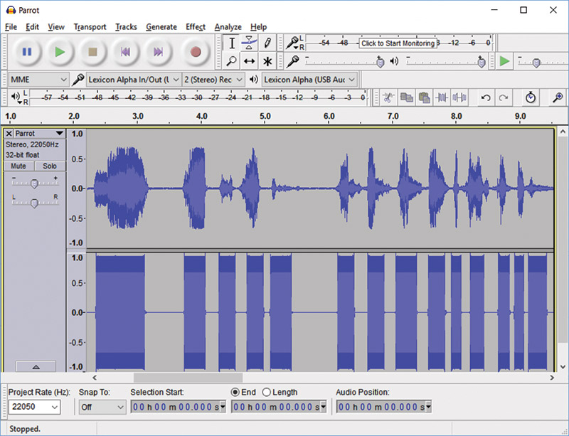
As the hit and miss nature of the jaw/audio sync was a common issue, some folks even went so far as to make a “tone track” version of a soundtrack to obtain more control over jaw motion from this circuit. A tone track is created by recording a custom stereo audio track with the spoken dialog on one side and activation tones on the other (Figure 5).
FIGURE 5. Audacity audio editor with audio track on top and "tone" track on the bottom.
The tone track is only sent to the Scary Terry and its purpose is to drive the jaw. The other track contains the actual spoken dialog that is sent to a speaker. Though this approach has the advantage of better jaw/audio sync, creating it is time-consuming, and once again makes changes to the dialog difficult as it requires a tedious reprogramming of the tones.
Three Levels are Better than One
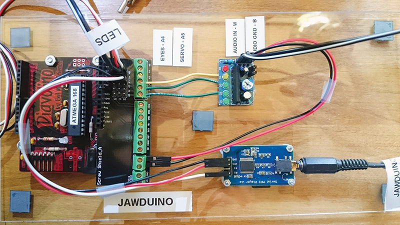
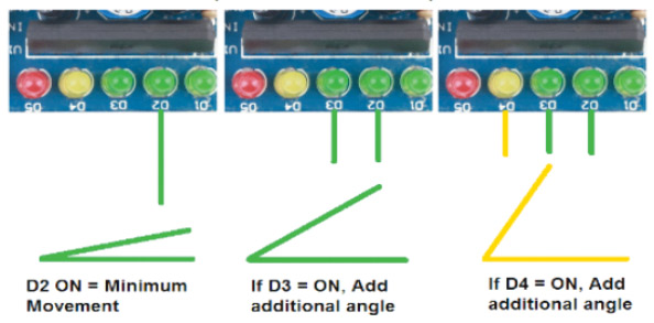
Recently, a new approach dubbed the “Jawduino” (Figure 6) has been making the rounds. It uses an LED VU meter and an Arduino to put a new spin on the audio/jaw sync problem (see the September 2017 issue of SERVO Magazine for construction details). This interesting circuit increases the jaw accuracy by using a simple five LED VU meter board. Dialog audio is fed into the LED VU meter board and the Arduino is wired to monitor the middle three LEDs.
FIGURE 6. Jawduino featured in the September 2017 issue of SERVO Magazine.
By tapping into these middle three LEDs, the Arduino is able to “read” the volume of the signal and then tell the servo to move to a correlating position (Figure 7).
FIGURE 7. LED VU meter and corresponding servo position targets.
This allows the Jawduino to react more accurately to audio volume levels and is a definite improvement over the Scary Terry design. However, all of the simple “volume to position” solutions miss an important aspect of recorded speech — one that has a direct bearing on jaw sync accuracy.
What’s the Frequency, Kenneth?
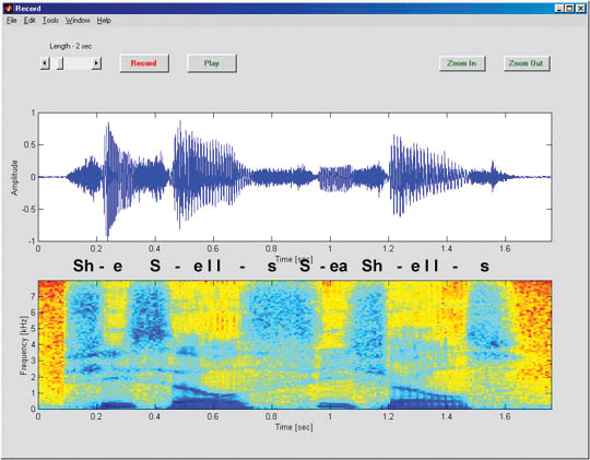
Spoken audio consists of a spectrum of frequencies. There are differing amounts of energy devoted to different bands depending on the phonemes that compose a given word. A good example of the differences in energy is shown in the spectrogram of the phrase “She sells sea shells” (Figure 8).
FIGURE 8. Sounds such as "sh" and "s" (sometimes called unvoiced sounds) contain a broader range of higher frequencies, while other (voiced) sounds — such as "e" or "ell" — contain mostly lower frequencies (image source www.ele.uri.edu/~hansenj/projects).
You can see that if we limit ourselves to using amplitude as the only criteria to determine jaw position, we would get some unexpected and less than satisfactory results. For example, we may see jaw openings for the sibilant sounds (letter “s” and the “shh” sounds), but comparably less deflection for the “e” sounds. This means there may be times where the jaw would open wide in reaction to sibilant sounds which is the opposite of the way we actually move our jaws when talking.
The ideal solution would be to sample the audio signal across its spectrum and collect information about each of the frequencies that have a significant impact on jaw position; then, use this information to direct jaw motions.
Can Wee Talk?
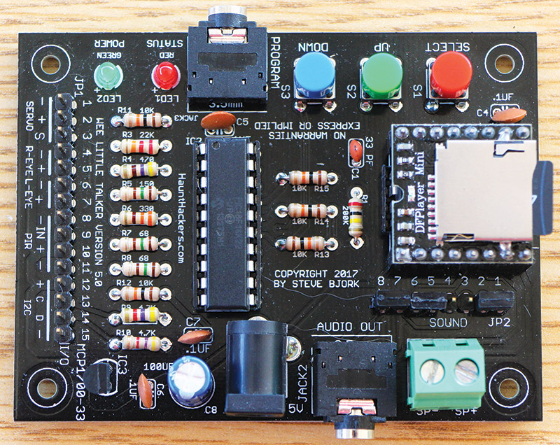
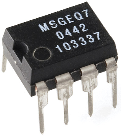
Steve Bjork from Haunt Hackers (see Resources) and the creator of the Wee Little Talker board, decided to tackle the jaw sync problem using a combination of hardware and software. On the hardware side, he started with the MSGEQ7 seven band digitally controlled spectrum analyzer chip (Figure 9).
FIGURE 9. The MSGEQ7 chip spectrum analyzer chip.
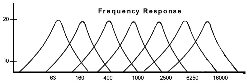
This small eight-pin chip can be used to collect samples of audio levels at seven frequencies (Figure 10).
FIGURE 10. The even bands covered by the MSGEQ7 chip.
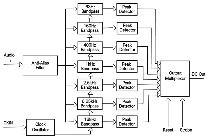
By toggling the Reset line and then pulsing the Strobe line a specific number of times, you can select the specific frequency you would like to measure (Figure 11).
FIGURE 11. MSGEQ7 block diagram.
Now that we have a chip that’s capable of capturing amplitude at multiple points in the spectrum, we need to connect this chip to an equally capable microcontroller. Steve chose the venerable PICAXE 20X2 chip.
By using its built-in Analog-to-Digital Converter (ADC), we can sequentially take samples from each frequency of interest.
Can You Hear Me Now?
When it comes to voice, frequencies below 400 Hz are not typically associated with jaw movement. Most are “plosives” associated with unvoiced sounds such as “t,” “k,” and “p,” and when recorded, are actually amplified as an artifact of the recording process (i.e., air expelled during speech that impacts the microphone element).
Alternately, frequencies above 2.5 kHz are typically sibilant sounds such as “ssss”/“shh,” and the human mouth normally produces these by bringing the teeth and jaw together. This means the frequencies we can sample from the MSGEQ7 chip for jaw motion are 400 Hz, 1 kHz, and 2.5 kHz.
The ADC in the PICAXE allows us to sample the amplitude on each of these frequencies with eight bits of resolution (value between 0 and 254).
So, rather than the original one bit of resolution offered by the Scary Terry circuit (i.e., ON and OFF) or the two bits of resolution offered by the Jawduino circuit (i.e., OFF, LOW, MED, HIGH), this new design will allow us to sample amplitude with eight bits of resolution (255 discrete positions) across three distinct frequency bands — quite an improvement!
If we sample each of these, we can get a clear picture of when the jaw needs to be open in order to more closely model the jaw position in relation to an audio file.
Now that we know what frequencies we need to sample, we can begin to build a system that can sample the sound and then move the servo.
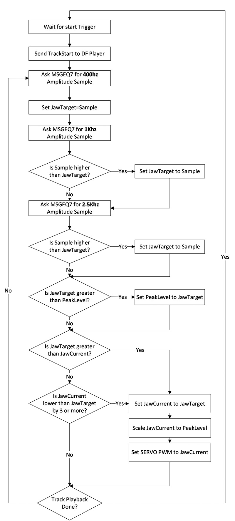
The complete code to do this is shown in the block diagram in Flowchart 1.
FLOWCHART 1.
Everything to Gain
The next feature the board offers is inherent non-volatile automatic gain control. The first time a new sound file is played by the DF Player, the Wee Little Talker board cleverly records the highest volume points in the audio file and — if it is not the full 255 value the ADC is capable of recording — it will create a “scaling” factor and store it in the EEPROM of the PICAXE. This avoids having to set the gain to get optimum jaw deflection when using an audio track that is recorded at middle or low volume.
Every time the sound file is played, the maximum volume level detected during playback is stored in EEPROM without the user having to take any steps to cause this to happen. This is a truly automatic gain control!
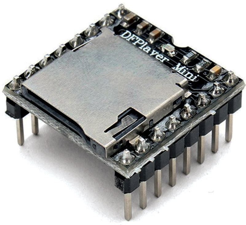
So, if having computing power, an EEPROM saved setup, LED, and servo drivers already on board weren’t enough, the Wee Little Talker also hosts the DF Mini MP3 player board. This is a full featured MP3 player with a built-in audio amplifier (Figure 12) and is the reason the board can offer yet another high-tech feature: a voice-driven menu system.
FIGURE 12. DF Player Mini MP3 player.
What’s On the Menu?
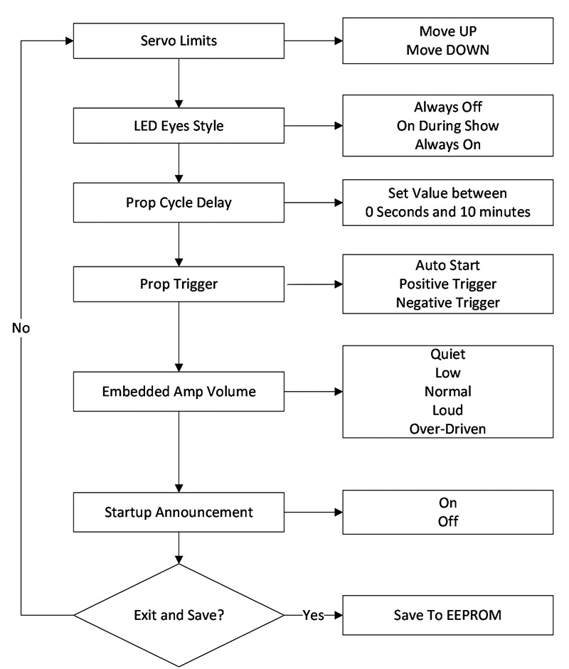
The Wee Little Talker has an onboard voice driven setup menu (see Resources for video demonstration). Using just three onboard pushbuttons, the Wee Little Talker board will verbally guide you through the entire setup of the system — no PC or external connections required. This is accomplished by having prerecorded voice prompts on a micro SD card and calling them one by one. The menu structure is shown in Figure 13.
FIGURE 13. Wee Little Talker voice prompt menu flow.
Just by stepping through the menu, you can program all of the features of the board. Here’s a quick overview of the menu options:
Servo Positioning: This adjusts the servo position to the maximum jaw open and closed positions of your specific servo and jaw system. This is crucial since it lets the Wee Little Talker board know the limitations of movement so it doesn’t drive the servo/jaw combo past the limits of your physical setup.
LED Eyes Style: This has three options: Always Off, On During the Show, and Always On. The most common setting is On During Show as it causes your skull’s eyes to light up at the beginning of the audio file and then turn off when it’s over.
Prop Cycle Delay: This is used so that after the audio file has finished playing, a delay is enforced before the board will respond to another trigger. This is useful to make sure the device isn’t being constantly triggered by an overzealous use of a footswitch pad or children standing in front of the prop and waving their hand in front of the PIR. Additionally, if the trigger is set to “auto start,” this value will be used as the delay between shows.
Prop Trigger: This has three options: Auto Start, Positive Trigger, and Negative Trigger. In Auto Start mode, the prop will start playing when powered up and repeat after the delay set in “prop cycle delay.” In Positive Trigger mode, a LOW to HIGH transition of the trigger input will cause the prop to start. This is commonly used for PIR sensors. In Negative Trigger mode, a HIGH to LOW transition will start the prop. This is commonly used for step switches or pushbutton start-up.
Embedded Amp Volume: This has five options that set the volume of the onboard DF Player Mini MP3 board. The values are Quiet, Low, Normal, Loud, and Over-Driven. Though many folks will probably use an external amplifier to make sure their prop is heard if it is to be used in a loud environment, the Over-Driven level is loud enough to allow a small desktop display to be clearly understood. The onboard amplifier makes it possible for you to place a speaker inside your talking skull for a truly all-in-one system.
Enough Talking! Now Wee Build!
So, now that we’ve thoroughly explored the Wee Little Talker board, let’s get started on creating its new home. There are multiple steps in this part of the project, but none of them are truly difficult. Take it a step at a time and you’ll be done before you know it. You can find a complete list of the products used and the corresponding links in the Resourcessection.
This build uses a skull with a removable skull cap which allows access to the inside. This is where the servo and controller will be installed. All the electronics fit inside which means the power supply cable and/or speaker trigger wires (if you are using them) are all that are running out of the skull. I prefer to use the second class skulls in order to save some money.
My attitude is that the imperfections improve the look! I don’t want it to look shiny and new.
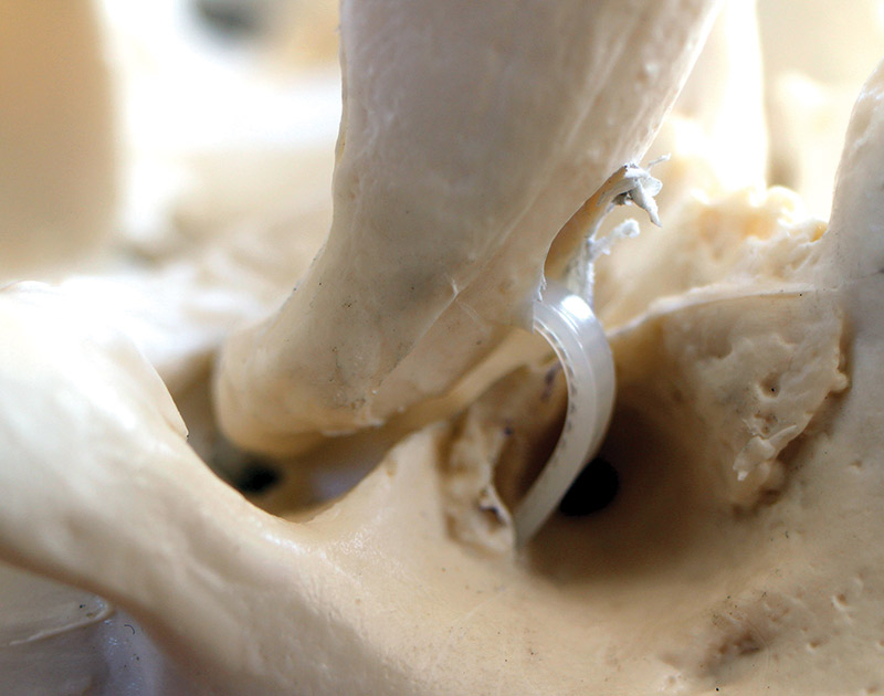
We begin the assembly by tackling the jaw first. It will be securely attached by drilling two holes in the jaw and then through the skull. A small zip tie will then be threaded through these holes and loosely connected (Figure 14). We will tighten these up when it’s time to finalize the installation, so leave them loose for now.
FIGURE 14. Jaw securely pivoting on the zip ties.
Choose a bit that is slightly larger than your zip tie. A 1/8” drill bit works for the ties I use. You don’t want it any larger than necessary as it will be sloppy. You do want the hole large enough to allow the zip tie to move freely, however.
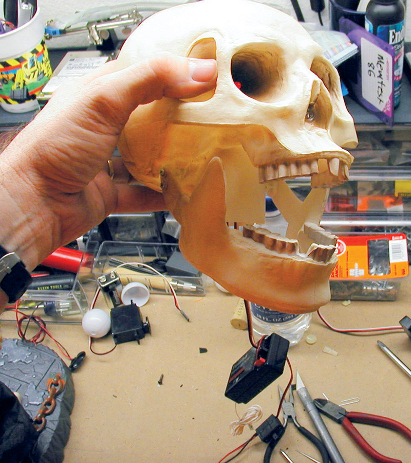
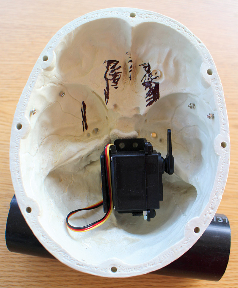
I like to grind down some of the interior of the skull before installing the servo bracket. This will allow the servo to rest lower in the skull, and it will take less material to build up a level mounting surface (Figure 15).
FIGURE 15. Can you grind between the lines?
The bracket is attached by laying a bed of ProPoxy and then seating the bracket. If you have not yet had the pleasure to work with this product, I suggest you stop what you are doing and immediately purchase some. (On second thought, why don’t you finish reading this article first and then go place your order!)
ProPoxy is on my short list of need-to-have products. It can be helpful in solving a variety of problems you will encounter as you build your own mechanisms. It consists of two parts that — when combined — can be shaped, sanded, drilled, and tapped to provide mounting areas for many situations. It makes me a better builder and saves me time. There is always a tube or two on my shelf.
Once this dries, the bracket should be firmly attached. If you would like some added security, you can drill and tap the ProPoxy to accept a couple of screws. This is one of the nice features of using this material. You can even make the bracket removable by coating it with a thin layer of Vaseline™ before placing it in the ProPoxy.
The addition of screws will be the method used to anchor it, which allows it to be removed in the future if necessary.
The servo should be assembled with an arm in place in order to align it properly. Then, a wire will be attached from the servo arm, through a hole drilled into the skull, and into the jaw. Take a minute to check out the location of the jaw attachment point and try to line up the servo arm. Don’t worry if you are off a bit as the hole in the skull through which the wire runs may be enlarged later. Next, cut the slot for the wire that will attach the jaw to the servo (Figure 16).
FIGURE 16. Enlarge the slot as needed. No one can see it.
The wire I use is 0.039 diameter stainless steel I get from McMaster-Carr. It is only sold in packs of 100/12 inch lengths, but I have found plenty of other uses for this wire in other projects. These are longer than you will need, but hold off cutting them for now. If you are adding LEDs for the eyes, you may need to enlarge the eye sockets to accommodate them.
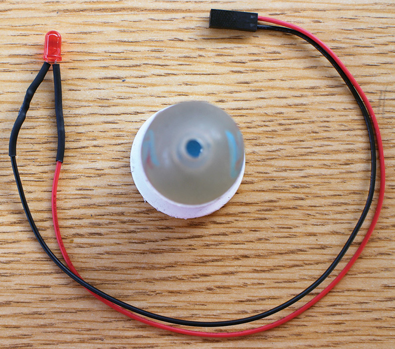
The same 1/8” bit you have been using should be fine for this, as well. You can simply use the plain LEDs or insert them into a pair of eyeball blanks. I purchased a pair of wired two-pin headers and soldered an LED to each one (Figure 17).
FIGURE 17. One eye prepared for installation.
The header attaches to the board and the LEDs are pressed into a hole you drill in the eyes. I then apply some hot glue to the eyeball to attach it to the skull. This is the method I use for my characters as it is an inexpensive upgrade that seriously improves the look.
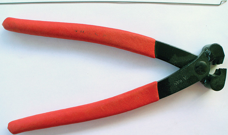
Finally, you will drill a small hole in the jaw to accept the wire that connects to the servo. Insert the wire in the slot that was cut earlier. Next, attach the wire to the servo horn which is placed in the 1:00 position on the servo. I use a special J bend tool to bend the wire to shape, but you can do the same thing with a couple of pairs of needle nose pliers (Figure 18).
FIGURE 18. The right tool for the job.
It is now time for a little disassembly work. Remove the jaw springs from the skull. This is a simple process that requires the removal of a couple of screws. Your jaw should now pivot smoothly.
Tighten up the zip ties a bit so the jaw moves easily, but is still pulled up to the skull. Place the wire next to the jaw attachment hole and after adding a couple of extra inches, mark your cut. I like to leave a small space between the teeth when the jaw is in the closed position to keep them from banging together when speaking.
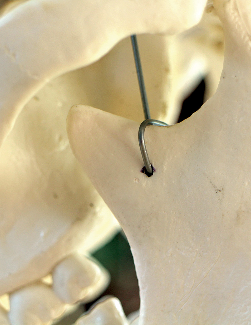
After inserting the wire through the hole, carefully bend the end to keep it from coming loose. Be careful with crimping down on the jaw with your pliers because it is easily damaged if you use too much force! Cut off any excess wire for a clean connection (Figure 19).
FIGURE 19. That wire is not coming off the jaw!
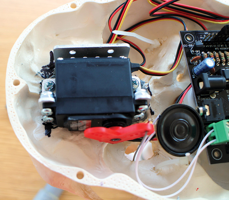
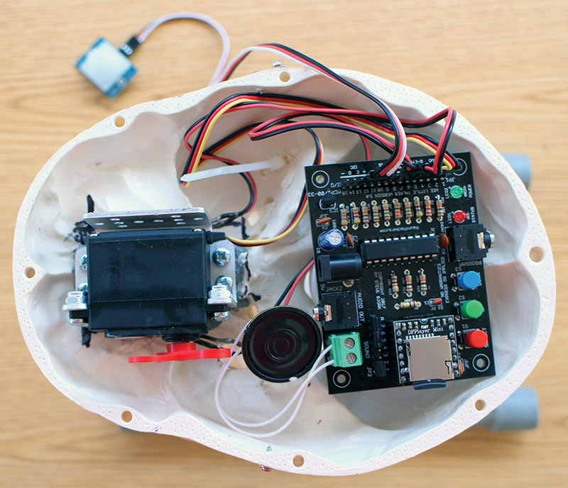
One additional hole you may want to drill is directly opposite the servo horn screw. This will give you access if you need to adjust the placement of the horn on the servo. Once all the parts are placed, it should look like Figure 20.
FIGURE 20. Speaker installed, along with the rest of the components.
Get Your Head in the Game!
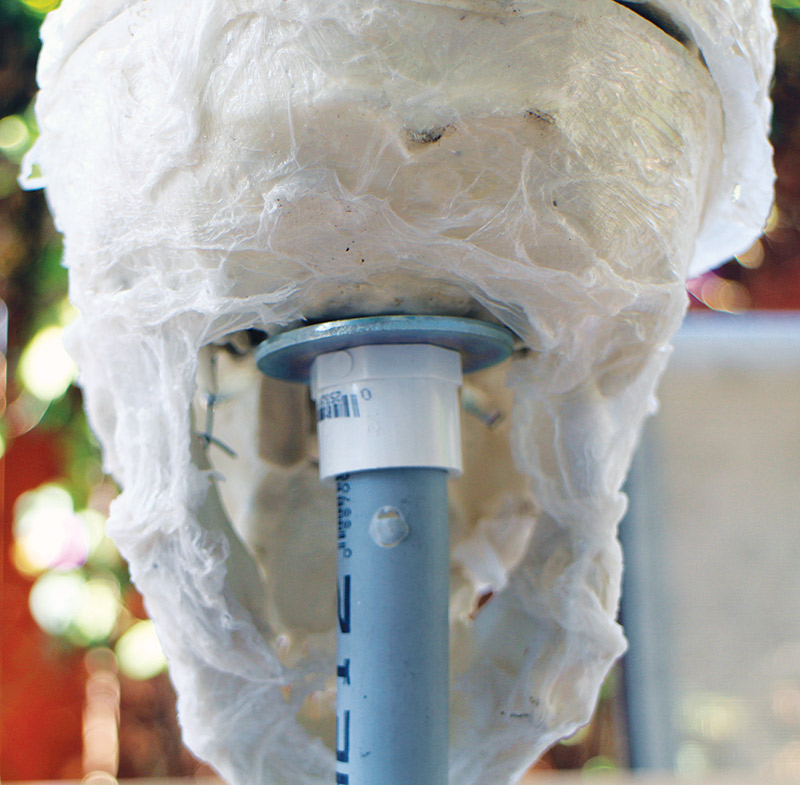
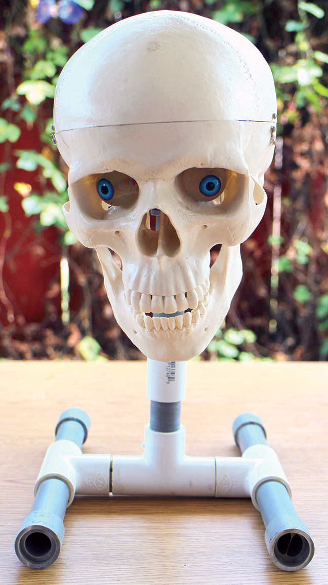
When I am connecting the skull to a body, I have found the easiest method is to use 1/2” PVC and a couple of connectors and washers (Figure 21 and Figure 22).
FIGURE 21. A couple of washers and some PVC parts provide the mounting point.
FIGURE 22. Completed talking skull set to entertain!
I solidify things with a couple of easily accessible screws to hold things tight. This makes a solid connection that can be easily undone if needed.
Another option is to use a long threaded rod with a selection of nuts and washers securely anchoring it in place. I have used this method when I’ve had a character that would be violently moving around. This let me run the threaded rod down through the spine and connect the end after it exited the pelvis. This makes for an extremely strong connection and greatly increases the strength of the spine.
Let me add a word of caution about installing the board in the skull. The temptation may be to just set it inside and close things up. I would recommend that you protect the board in some way to prevent damage should it move around and come in contact with the servo bracket.
We do not want any undesirable shorts to occur! Letting out the blue smoke is not a good thing here. Something as simple as adding double-sided tape to cover the contacts on the bottom of the board and secure it down is usually sufficient.
Hey Good Looking!
Are you unsatisfied with the appearance of a plain looking out-of-the-box skull? Let me suggest that you do some additional modifications.
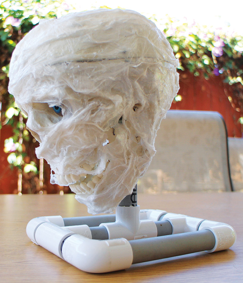
The first method I learned was from William Ramsey (a.k.a., Dr. Terror Eyes) at the Halloween and HauntFest show in Dallas last year (see Resources). Using an inexpensive .5 mil painting drop cloth, you can apply it to the skull and then use a heat gun to shrink the plastic so it adheres to the skull. You can then add color to bring out the texture and make it pop as shown in Figure 23 and Figure 24.
FIGURE 23. Adding plastic wrap to take it up a notch.
FIGURE 24. Look at all that great texture!
Two of my favorite products for this are the line of gel stains from Minwax and the Tandy Leather stains (Figure 25 and Figure 26). If you are looking for a more ghoulish appearance, this makes it look much scarier!
FIGURE 25. My favorite colors.
FIGURE 26. The extra effort paid off!
You can take it up another level by sculpting directly on the head. Steve devoted an entire article to this process in the June 2017 issue of SERVO Magazine in his DIY animatronics column.
Using this method allows you to convert that skull into any character you desire.
Exit Stage Left
Once you have successfully built a talking skull, you will find plenty of other uses besides adding them to your complete characters. You can place one atop a pile of books on a shelf or install one in a crystal ball. This same platform will allow any creature you desire to gain its talking voice.
Birds, monkeys, dragons, and more can now put their vocal chords to work! The progress made in this area over the past five years has been tremendous. I am excited to see where it will be five years from now!
Once you start adding this feature to your characters, you may find that they do not seem complete without the ability to talk. Once you give one a voice, they will all want to be able to speak! NV
Talking Skull Control Board Feature Comparison Matrix
Key: “✔” = yes, “✘” = no, “ “ = N/A
Scary Terry Board
Jawduino
Wee Little Talker
Drives servo to control jaw position
✔
✔
✔
Controls LED eyes
✔
✔
✔
Requires no onboard “tuning” via potentiometers
✘
✘
✔
Uses multi-frequency audio sampling for jaw sync
✘
✘
✔
Setup can be programmed without an external computer
✔
Can be triggered by PIR or pushbutton switch
✔
Adjustable “hold off” time to prevent retriggering
Steve Bjork started Haunt Hackers as a site to promote DIY boards for the hobbyist. This differentiates these boards from his professional line that he sells to commercial haunts and theme parks.
I would like to take this opportunity to thank my son, Bryan Koci for his hard work in producing the pictures for the cover. Unfortunately, you only get to see a single sample from the many fantastic images he took. Bryan owns a successful photography company (Red Tie Photography), as well as works as the Media and Marketing Manager at Whissel Realty. His expertise helps to bring my creations to life and allows me to share them with you (see Resources).
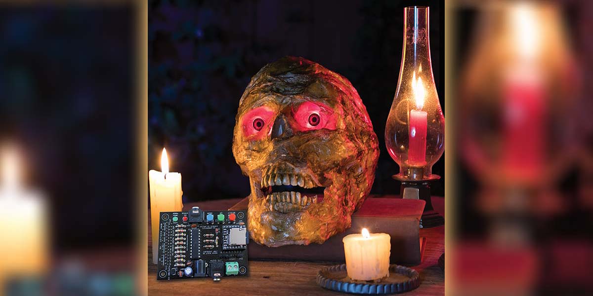


 I would like to take this opportunity to thank my son, Bryan Koci for his hard work in producing the pictures for the cover. Unfortunately, you only get to see a single sample from the many fantastic images he took. Bryan owns a successful photography company (