In our modern age, the importance of digital electronic data communications by telephone lines, through a modem, special high-speed lines, or over the airwaves by radio cannot be overstated. The transfer of information via these media is critical for the successful operation of government, military, business, and banking. Without this technology, our information age and the Internet would be impossible.
The reliability of data communications over distance is of the utmost importance because of the critical requirements of its users. If the medium cannot be relied upon for error-free performance, it is useless. The damaging effects that can compromise the system are noise, distortion, and interference. These three gremlins have the ability to turn a digital one bit message into a digital zero bit and vice versa. If this reversal of a bit occurs, then an error has crept in, possibly undetected. This scenario could be disastrous.
Since we cannot guarantee a perfect medium between a source transmitter and a destination receiver, some method to detect errors must be employed. Thankfully, there are some systems that can do this. Parity check and checksum are two ways, but they have limitations. Another method is a code called Cyclic Redundancy Check (CRC). CRC is a popular and powerful means to ensure that a transmitter and receiver can communicate data reliably, even in the worst of conditions. CRC is so well regarded that the Internet relies on it for error detection.
In this article, I will present a short course on CRC and supply the knowledge needed to implement simple digital electronic circuits to perform CRC. Later, I will present a modification to the concept, where a method of data encryption, along with the normal error-detecting feature, can be utilized.
Cyclic Redundancy Check is a code — or algorithm — that has three basic and endearing qualities: it provides extreme error detection capabilities, requires a minimum of hardware and software, and is easy to implement. These advantages can make the application of this system by hobbyists and hardware hackers a reality. I will demonstrate that CRC circuits are very easy to breadboard and utilize.
Parity check, checksum, and CRC all work by applying an algorithm to a message. This algorithm, or code, produces a binary value that represents the message in some digital logic way. This value is then appended to the end of the message before it is transmitted out. The receiver at the other end of the link receives the message and binary value combination, then applies the same algorithm to the message to produce its own binary value. The receiver compares the two values and, if they are equal, then the message was received correctly. If they are not equal, then the receiver tells the transmitter to retransmit the message.
The primary benefit of CRC is that it can detect more types of data errors than the other two methods. For instance, it can detect all single bit errors, all double bit errors, any odd number of errors, and most burst errors. Parity check, on the other hand, can only detect single bit errors, while checksum can detect all single bit and some multiple bit errors. Obviously, CRC is the most robust of the group.
Modulo-2 Arithmetic
In exploring the theory behind CRC, we will begin with a short lesson on modulo-2 arithmetic. Modulo-2 arithmetic is normal binary addition or subtraction, but is not concerned with carrying or borrowing, as in decimal arithmetic. For those familiar with logic half adders, it's just the exclusive-OR logic operation. For example, adding, subtracting, and multiplying, respectively, are as follows:
    1111    1111    11011<br />
 <u> + 0110</u>  <u>- 0110</u>   <u>x 1101</u><br />
    1001    1001    11011<br />
                   00000<br />
                  11011<br />
                 <u>11011</u>
10101111
In short, to add the bits in the columns when there is an odd number of binary ones in a column, then the sum of that column is a binary one. If there's an even number of ones in the column, then the sum of that column is a binary zero. It's that simple. Modulo-2 long division, which we'll discuss next, is not so intuitive, but, by studying the examples, the steps will become clear.
Cyclic Redundancy Check
Cyclic Redundancy Check can be described in three ways: modulo-2 arithmetic (which I will continue with next), polynomial arithmetic, and digital logic circuits. Because of space limitations, I will not be able to present the polynomial arithmetic aspect, but we will look at some circuits. We will have to do some simple math; since we're just dealing with ones and zeros, hopefully it won't be too difficult.
In a transmitter, let us define message M as being m bits long. This m bit message will be divided, using modulo-2 long division, by a pre-defined binary pattern divisor P. The division, just like regular long division, will produce an r bit long remainder R known as the Frame Check Sequence (FCS). From now on, I shall refer to remainder value R as the FCS to prevent confusion with other remainders that will be discussed later. The r bit FCS will be appended to the end of the m bit message M to be sent out as the data transmission.
The previous paragraph has thus defined the philosophy employed in the transmitter. There are a few loose ends. The length of pattern P, therefore, must be r + 1 bits long. The number of bits of the FCS must be less than the number of bits of message M, or r < m.
The long division process can be done by either software or, as I will later show, by hardware. The division is the easiest to do in software, but hardware is much faster. To perform the division properly, message M must initially be padded with r zero trailing bits. At the end of the division process, the r zero bits will be replaced by r remainder bits to become the FCS.
The transmitter's pre-defined pattern divisor P is a code word or key that must be known by the receiver, too. The quotient produced by the division has no function in this scheme and is thus ignored. Incidently, though, the number of bits q of quotient Q will be the same as the number of bits of message M, or q = m. Later, I will show how the quotient can be used in a method of data encryption.
When the receiver receives the data — message M with the FCS — it divides this combination, in modulo-2, by the identical pattern divisor P that the transmitter used. If the remainder of this division is zero, then no errors crept into message M during transmission and the validity of the message can be ensured. The quotient of this division is, again, not used in this process and is also ignored.
With this much now known, see Example 1 for a reference regarding using modulo-2 long division.
1101010110 <-Q
           <u>             </u>      <br />
P-> 110101|1000110100000 <-M<br />
           <u>110101</u><br />
            111011<br />
            <u>110101</u><br />
              111010<br />
              <u>110101</u><br />
                111110<br />
                <u>110101</u><br />
                  101100<br />
                  <u>110101</u><br />
                   110010<br />
                   <u>110101</u><br />
                    01110 <-R
EXAMPLE 1.
The remainder, 1110, is four bits long, but, since we know that the length of the remainder must be one bit less than the divisor for a total of five bits, we add a zero to the most significant bit (MSB) so it becomes 01110. The quotient, just for the sake of completeness, also has a zero added to the least significant bit (LSB), because its length must be equal to the message for a total of ten bits.
The FCS remainder R, 01110, is appended to message M, 1010001101, to become 101000110101110, which is transmitted. The receiver obtains the message and divides 101000110101110 by the same pattern P to produce, if there are no errors, a remainder of zero, as we will see in the modulo-2 long division shown in Example 2.
                1101010110 <-Q<br />
          ________________    <br />
P-> 110101|101000110101110 <-M<br />
           <u>110101</u><br />
            111011<br />
            <u>110101</u><br />
              111010<br />
              <u>110101</u><br />
                111110<br />
                <u>110101</u><br />
                  101111<br />
                  <u>110101</u><br />
                   110101<br />
                   <u>110101</u><br />
                    00000 <-R
EXAMPLE 2.
Since the remainder is zero, no errors occurred during transmission and the message is valid and reliable.
Digital Circuits
Having now finished covering the fundamentals, you might be wondering how all this gets us to some practical logic circuits. The truth of the matter is that the mathematical division operations we just discussed can be represented by digital shift registers. In addition, the binary ones and zeros of the pattern-divisor correspond to the presence or absence of a simple exclusive-OR logic gate.
This information tells us how to build the circuit that will be the pattern divisor, which will generate the FCS used in CRC. A branch of error control code theory called cyclic codes is what we have been talking about previously. Fortunately, shift register circuits and exclusive-OR gate logic can imitate the function of modulo-2 math and cyclic codes.
To build the divisor circuit, the number of shift-registers and exclusive-OR gates needed is determined by the bits of the divisor pattern P. If we have j total number of bits in the pattern P, then we need j - 1 number of shift registers. And, if k is the number of binary one bits of P, then k - 1 will be the number of exclusive-OR gates needed.
Let us now present the schematic for the pattern divisor circuit in Figure 1.
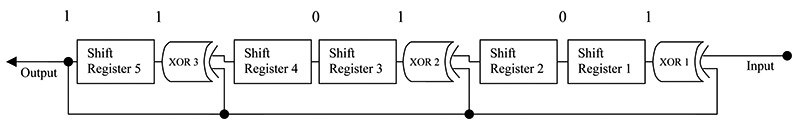
FIGURE 1.
Please notice that this circuit uses a serial logic feedback arrangement. This will allow the serial data message to be divided in modulo-2 long division arithmetic. Also, a circuit usually has the input on the left and the output on the right, but here, I have reversed it to more closely resemble the convention used in writing binary numbers, where the MSB is on the left and LSB is on the right. This way, it will be easier to understand the connection between the two.
As you can see, it is relatively simple for this circuit to perform a long division operation in modulo-2 on serial data. The shift register chip I used for this project is a TTL 74273 and the exclusive-OR gate chip is a 7486. The 74273 has eight independent shift registers with a common clock and master reset. The registers can be connected together or have the exclusive-OR gates inserted in between, according to where the one bits of the pattern are located.
Figure 2 is the schematic for the whole circuit I used to demonstrate the CRC principle.
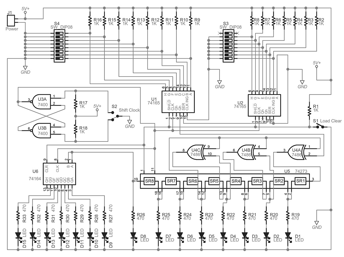
FIGURE 2.
In the lower right is the divider circuit, just mentioned. On top is the circuit to input the message to be serially shifted through the divider circuit. It uses two 74165 eight-input parallels to serial shift registers. On the lower left is a 74164 serial to parallel eight-output shift register to hold and display the output data.
There is a de-bounced switch to manually operate the shift-clock and another logic switch to simultaneously load the 74165s with the message and clear the registers of the 74273 and 74164 to zero. The LEDs will be used to indicate the states of the registers and values that we are interested in.
To make the circuit work, message M plus the padded five zeros — 101000110100000 — must be applied to the 74165s, as shown, by setting the input data switches high or low, accordingly. Then, to load the 74165s with the message and to reset the 74273 and 74164, the clear-load line must be momentarily brought low, then high. It is imperative that the registers are initialized to the zero state or our calculation will be wrong.
Next, it is a simple matter of toggling the shift-clock control to shift the message through the divider circuit until the quotient 1101010110 appears at the end of the 74164. The FCS remainder value 01110 will appear from the divider circuit, proving the operation of the transmitter's CRC circuit. Do not shift any further; any more shifting will corrupt the remainder. Since the message with the five zeros is 15 bits long, it should take 15 toggles of the shift-clock to move it through to the end.
This design would probably be very close to an actual transmitter circuit employed in a system. What I have not shown is that the FCS remainder value would be appended to message M in another circuit and then shifted out to be encoded in the format to be transmitted. This format would either be a modem for a telephone line or a modulator for a radio transmitter. I omitted this, as I only wanted to show how the basic divider circuit worked and what peripheral circuits were needed to accomplish that.
Another way of looking at this circuit is as if it was being employed at the receiver end, since both the receiver's divider circuit and the transmitter's divider circuit are identical. With this way of looking at it, the lower part of the circuit in Figure 2 would be the receiver and the top part of the circuit would simulate the transmitter. So, according to your point of view, the circuit could separately simulate both ends of a network.
With this in mind, if the five padded zeros appended to the message are replaced with the FCS value of 01110 and the clear-load is initiated, then, after toggling the shift-clock 15 times, the quotient will again appear at the output LEDs, but this time, the divider circuit will show a remainder value of zero (no LEDs illuminated), thus showing that the receiver received the message correctly, proving the CRC operation.
Data Encryption
If you will recall, I said that the long division process by the transmitter CRC circuit, which produced the FCS remainder, also produced the quotient Q. This quotient, as I said, being an unneeded byproduct of the process, was ignored. To implement a method of data encryption, this quotient can be utilized. Hence, instead of transmitting the message and FCS in the usual way, the quotient and FCS could be transmitted. The receiver, in turn, instead of dividing like before, would simply multiply the received quotient value by pattern P in modulo-2 to produce the real message and, using the FCS in the normal way, check for any errors.
Thus, when the receiver would receive a message (quotient) and FCS, it could separate the two and store the FCS to be used for comparison later. After multiplying, the product of P and Q is M — the real message M, and, with this product, a calculated FCS value. This calculated FCS part could then be compared with the received and stored FCS. If they were equal, then the real message, which was just calculated, would be confirmed correct, valid, and reliable.
By sending the quotient and FCS as the data, if this encoded message (quotient) is intercepted, it cannot easily be deciphered without knowing the key, which is pattern P. Thus, the data could obtain a high level of security and privacy between the communicating sites.
Using our previous example, let us use Example 3 to confirm the multiplication arithmetic of the receiver. If the least significant five bits of the product in Example 3, which is the calculated FCS, are equal to the received FCS, then the message is valid. All that is needed for this concept to work is a circuit for the receiver to perform the modulo-2 multiplication, using the pattern P.
          Q-> 1101010110<br />
              <u>    110101</u> <-P<br />
              1101010110<br />
             0000000000<br />
            1101010110<br />
           0000000000<br />
          1101010110<br />
         <u>1101010110     </u>   <br />
         101000110101110<br />
             <br />
    M-> (1010001101)(01110) <-R
EXAMPLE 3.
Figure 3 is the schematic of such a circuit. Notice that it is similar to the divider circuit, using shift registers and exclusive-OR gates, but now in a feedforward logic configuration. By rearranging the divider circuit in Figure 2 to be the multiplier circuit of Figure 3, the demonstration circuit can now verify the data encryption method. Load the 74165 chips with the quotient and FCS value, 110101011001110, toggle the shift-clock just 10 times, and watch the real message and calculated FCS, 101000110101110, appear at the LEDs.
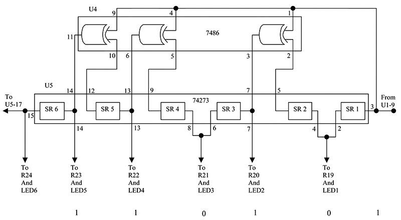
FIGURE 3.
Here, we only had to shift 10 times to get the 15-bit product (message and calculated FCS). Five more toggles of the shift-clock would shift in the actual FCS, but, unfortunately, the multiplier circuit would corrupt the FCS, so some minor modifications would be needed to be able to see the value. Just know that the transmitted FCS is present and waiting to be shifted in and received.
Now, I must confess that, although I do not know of any system that uses this particular method of data encryption, I have shown that it is a mathematically and electronically possible technique.
Conclusion
Although Cyclic Redundancy Check is not as advanced as the error correcting codes that are now available, it is an excellent means of detecting transmission errors in digital data communications. CRC is popular and is used in many systems, like the Internet, Ethernet, Public Switched Data Networks, Token-ring Networks, and amateur packet radio. The mathematics and the electronics are very simple and the circuits can be easily constructed. By inferring from the given example, circuits for any divisor pattern can be produced.
We also found that, with a slight modification to the CRC philosophy, a data encryption method could be realized that would effectively privatize information between networks and, most importantly, would still possess all the error detection capabilities, too.
What I did not elaborate on is how the association between modulo-2 math and the digital circuits works and what pattern code words are best. This, unfortunately, would require a whole course on the theory of error control codes, with all of the attendant linear and abstract algebra. It would be difficult to condense into just a few pages.
Fortunately, there are many books on the subject for those who want a deeper understanding. Internet searches for CRC will also provide much information on this topic. What I have hopefully done is given enough guidance for you to experiment with Cyclic Redundancy Check for yourself. NV