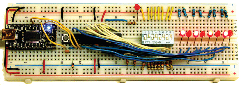
FIGURE 1. BreadboArduino chaser lights.
Recap
In Part 1 of this series, we looked at the software side of Digital I/O (DIO) as it is done in the Arduino using the sequentially numbered pins on the Arduino board. We wrote a library of functions like the Arduino DIO functions but used regular C concepts and tools (AVRStudio, WinAVR, avrdude, avrlibc, etc.). In Part 2, we saw that the Arduino pins are simple abstractions of the deeper AVR microcontroller’s concept of ports that are eight-bit arrays of pins, and then we wrote a library that specifically handles ports and their pins as they are used by raw AVRs. Now in Part 3, we will drop the abstractions and look at how DIO is really done in AVRs using the tools available in C, without having to write special libraries to manipulate the ports and pins for DIO.
So, Part 1 was a high level abstraction for DIO; Part 2 was a mid-level abstraction; and in Part 3, we will look at the raw low level stuff with no abstractions involved. After we see how the professionals do this (yes, it will be on the test), we will (mercifully) build a set of low level macros that will help you do things with DIO without requiring that you be a certified C guru. [BTW, if you know what PORTB &= ~(1<<PB5); does immediately without having to think about it, then you are certifiable.] Since we are determined to get as close to the machine as possible, we will demonstrate the DIO input with an eight-pin DIP switch and the DIO output with eight LEDs using an ATmega328 on a breadboard (as shown in Figure 1). We looked at the BreadboArduino in Smiley’s Workshop 21 (See series sidebar at the right). The parts kit is available from Nuts & Volts.
Theory
Bitwise Operators
| Operator |
Name |
Example |
Defined |
| ~ |
Bitwise complement NOT |
~x |
Changes 1 bits to 0 and 0 bits to 1 |
| & |
Bitwise AND |
x&y |
Bitwise AND of x and y |
| | |
Bitwise OR |
x|y |
Bitwise OR of x and y |
| ^ |
Bitwise exclusive OR |
x^y |
Bitwise XOR of x and y |
| << |
Left shift |
x<<2 |
Bits in x shifted left two bit positions |
| >> |
Right shift |
x>>3 |
Bits in x shifted right three bit positions |
TABLE 1. Bitwise Operators
Bitwise operators are critically important in microcontroller software. They allow us to do many things in C that can be directly and efficiently translated into microcontroller machine operations. This is a dense topic, so get out a pencil and piece of paper and work through each of the examples until you understand it.
In case you’ve ever wondered how to tell what is true and what is false, for bitwise operators which use binary logic (single bits), 1 is true and 0 is false.
We discussed binary vs. hexadecimal vs. decimal in Workshop 3, but to refresh: A byte has 256 states numbered 0 to 255. We number the bits in a byte from the right to the left as lowest to highest:
bit #    76543210<br />
myByte = 01010101 binary = 0x55 hexadecimal<br />
   = 85 decimal
Look at the truth tables for AND ‘&’, OR ‘|’, XOR ‘^’, and NOT ‘~’:
AND ‘&’     OR ‘|’      XOR ‘^’     NOT ‘~’<br />
0 & 0 = 0   0 | 0 = 0   0 ^ 0 = 0   ~1 = 0<br />
0 & 1 = 0   0 | 1 = 1   0 ^ 1 = 1   ~0 = 1<br />
1 & 0 = 0   1 | 0 = 1   1 ^ 0 = 1<br />
1 & 1 = 1   1 | 1 = 1   1 ^ 1 = 0
Now, memorize them. Ouch, but yes, I am serious.
ORing
We can set bit 3 to 1 in a variable, myByte, by using the Bitwise OR operator ‘|:’
myByte = 0;<br />
myByte =  myByte | 0x08;
To see what’s happening, look at these in binary:
bit #    76543210<br />
myByte = 00000000 = 0x00<br />
  0x08 = 00001000 = 0x08<br />
—————————————————————————<br />
OR ‘|’ = 00001000 = 0x08
We see that bit 3 is 1 in 0x08 and 1 | 0 = 1, so we set bit 3 in myByte.
Suppose myByte = 0xF7:
bit #    76543210<br />
myByte = 11110111 = 0xF7<br />
  0x08 = 00001000 = 0x08<br />
—————————————————————————<br />
OR ‘|’ = 11111111 = 0xFF
Or maybe myByte = 0x55:
bit #    76543210<br />
myByte = 01010101 = 0x55<br />
  0x08 = 00001000 = 0x08<br />
—————————————————————————<br />
OR ‘|’ = 01011101 = 0x5D
This shows that only bit # 3 of myByte is changed by the OR operation. It is the only bit equal to 1 in 0x08 and ORing 1 with anything always yields 1, so you can use it to ‘set’ a bit regardless of that bit value.
ANDing
Now let’s do the same thing with the & operator.
We can clear bit 3 with:
myByte = 0xAA;    <br />
myByte =  myByte & 0xF7;
 bit #    76543210<br />
 myByte = 10101010 = 0xAA<br />
   0xF7 = 11110111 = 0xF7<br />
—————————————————————————<br />
AND ‘&’ = 10100010 = 0xA2
Or maybe myByte = 0x55:
 bit #    76543210<br />
 myByte = 01010101 = 0x55<br />
   0xF7 = 11110111 = 0xF7<br />
——————————————————————————<br />
AND ‘&’ = 01010101 = 0x55
From this, you see that ANDing with 1 leaves the bit value the same as the original bit, and ANDing with 0 clears that bit regardless of its state, so you can use ANDing with 0 to ‘clear’ a bit value.
Setting and clearing bits is very important in AVR microcontrollers since the plethora of peripherals available are set up by either setting or clearing the hundreds of bits in dozens of byte-sized registers.
Setting and Clearing Bits
In each of the above cases, we are only dealing with a single bit, but we might be interested in any or all of the bits. Another important feature of using bitwise operators is that it allows us to set or clear a specific bit or group of bits in a byte without knowing the state of — nor affecting — the bits we aren’t interested in. For example, suppose we are only interested in bits 0, 2, and 6. Let’s set bit 6, regardless of its present value, then clear bits 0 and 2, also regardless of their present value and — here’s the trick — we must leave bits 1, 2, 4, 5, and 7 as they were when we began.
NOTE:
myByte = myByte | 0x08;
is the same as
myByte |= 0x08;
which we will use from now on. To set bit 6, we OR myByte with 0100000 0x40:
      myByte = 42;<br />
       myByte |= 0x40;
bit #    76543210<br />
myByte = 00101010 = 0x2A<br />
  0x40 = 01000000 = 0x40<br />
—————————————————————————<br />
OR ‘|’ = 01101010 = 0x6A
Next, we want to clear bits 0 and 2 so we AND 11111010:
myByte &= 0xFA;
    bit #    76543210<br />
    myByte = 01101011 = 0x6B<br />
    0xFA = 11111010 = 0xFA<br />
    ————————————————————————<br />
     AND ‘&’ = 01101010 = 0x6A
So, in summary, we set bits with ‘|’ and clear bits with ‘&.’ If you are going ‘Oh my gawd!’ at this point, I hope it is because you are surprised that you actually understand this. If it isn’t, then get that pencil and paper, and go back till you do.
XORing
Suppose we want to flip the highest four bits in a byte while leaving the lowest four alone. We could use a mask with the bits you want to flip set to 1 and the bits you don’t want to flip set to 0:
    myByte = 0xAA;<br />
    myMask = 0xF0;
myByte ^= myMask;
    bit #    76543210<br />
    myByte = 10101010 = 0xAA<br />
    myMask = 11110000 = 0xF0<br />
    —————————————————————————<br />
   XOR ‘^’ = 01011010 = 0x5A
XORing is used a lot in cryptographers, but not a lot by us mortals.
NOTing
Using the above example, we could clear those bits in myByte using the NOT on the mask, then AND it with myByte:
    myByte = 0xAA;<br />
    myMask = 0xF0;
    myMask = 11110000 = 0xF0<br />
     ~    myMask = 00001111 = 0x0F
myByte &= ~myMask;
    bit #    76543210<br />
    myByte = 10101010 = 0xAA<br />
  ~ myMask = 00001111 = 0x0F<br />
    ————————————————————————<br />
   AND ‘&’ = 00001010 = 0x0A
Shift Operators
The shift operators can be used to radically speed up multiplication and division IF you use numbers that are a power of 2. You might want to do this for tasks like averaging ADC readings. When we study ADC, you’ll see that sometimes we can get more accurate results if we take a bunch of readings and average them. My first inclination was to take 10 readings and then divide by 10. I chose 10 because I’ve got that many fingers, but if I had chosen eight or 16 then my division would be much faster using >>. If I divide by 10, the compiler has to call a large and complex division function and floating-point data types, but if I divide by eight it only needs to shift bits three positions to the right. Three quick right shift operations versus lots of time and program space — the tradeoff is precision.
Let’s say my readings were:
54, 62, 59, 57, 60, 59, 56, 63 = 470
The sum is 470 and 470 / 8 = 58.75
Remember that the largest decimal number that fits in an eight-bit byte is 256, so we must store 470 in a 16-bit integer (0000000111010110):
myTotal = 470
  bit # FEDCBA9876543210 (in Hex)<br />
myTotal 0000000111010110
If we shift this right three times, it becomes:
myAverage = (myTotal >> 3);
bit # FEDCBA9876543210 (in Hex)<br />
  >> 3 <span style="color:#FF0000">000</span>0000000111010<span style="color:#FF0000">110</span>
The low three bits (110) fall out of the AVR and have to be swept up later. [You didn’t believe that did you? They actually just disappear.] Anyway, the value now (ignoring the leading zeros) is 111010 which is decimal 58. Note that 58 is not 58.75, but you did save both time and program space so you have to decide which is better to use. The binary averaging gets you closer than all but two of the eight readings (59) and it does it lightning fast so if you are time constrained, the tradeoff should be obvious.
The Ternary Conditional Operator
Since we are already in about as deep as it gets, let’s look at one last dense thing: the ternary conditional operator. (Don’t you just love the way programming concepts get named? Ternary conditional operator, sounds like it means something that a programming guru might spout out in a stream of trying to scare you out of competing with him.) Unfortunately, even though this operator is quite useful it is not only a mouthful to say, but it’s a bit of slog trying to get your head around it. It looks like this:
a ? b : c
It says that given the condition ‘a,’ if that condition is true, then do ‘b,’ if it is false, do ‘c:’
[condition] ? [do this if true] : [do this if false];
A condition is any combination of variables, operators, and function calls that produce a single value. Since this is a logic condition, then any result of 0 is false and any other result is true.
For instance, if you want to turn on a fan if the temperature is above 150° F, or to turn off the fan if it is below 150° F, you could use:
temp > 150 ? Fan(ON) : Fan(OFF);
The condition: temp > 150 is evaluated to see if it is true or false. If it’s true, then the function Fan(ON) is called; if it’s false, Fan(OFF) is called. At this point, you might be yelling at the page: “Hey, I can do this with an ‘if’ expression!” You actually could, as follows:
if( temp > 150)<br />
    Fan(ON);<br />
else if( temp < 100)<br />
    Fan(OFF);
Since one of our goals is to learn C — which sometimes means learning several equivalent ways to do the same thing — you ought to get used to the ternary conditional operator because you will see it a lot, and we will use it in the digitalio library.
Yet Another Really Dumb Error
I like to share my really dumb errors with folks so that they can see that even those of us who ought to know this stuff by now sometimes make embarrassing mistakes. So, what is wrong with the following?
value ? (PORTD != (1<<pin)) :<br />
   (PORTD &= ~(1<<pin));
Well, when you have a bit of presbyopia and are squinting at the screen you may not see the problem. When you write this in your code, the compiler may just incorrectly assume that you know what you are doing and not even give you a warning since what you wrote is perfectly legal in C — but not at all what you intended. The compiler didn’t give me a warning and I futzed away a half hour before I finally saw that I’d used a ‘!’ in place of a ‘|’. IMHO, this is yet another reason to use macros. If I had written this with macros for the set and clear operation, then it would be:
value ? pin_set(PORTD,pin) :<br />
   pin_clear(PORTD,pin);
And I wouldn’t have made that typo. In fact, if I get the pin_set macro correct, then I’ll never make that dumb mistake again. Which neatly brings us to ...
Macros Can Help
If we want to clear the 0 bit in PORTB, we write: PORTB &= ~(1<<PORTB0). I’m sorry, but this is just nasty looking. It is the C way of doing things, but listen up my friend because now I’m going to give you some truth. If you want to be a professional C programmer and get to wag your huge wagging thing that other pros wag, then you not only have to memorize the bitwise operators, you have to use them raw — and you must scoff at folks who use simplifying macros. However, if you are more interested in getting the job done than in wagging your C programming skills at people, then you might want to use a set of simplifying macros that encapsulate all those mind-bending operators into something with a descriptive name attached to them. Like maybe bit_clear(PORTB, PORTB0) instead of PORTB &= ~(1<<PORTB0.
So, let’s save a few brain cells and write a small header file: bitwise.h. That will provide us macros with clear names for these operations. Be sure and note, however, that if you are taking a class on C programming, the teacher will quite correctly make you use the actual operators (and it will be on the test). If you aren’t a full time C programmer, then these macros can help to make your life easier:
#define bit_get(p,m) ((p) & (m))<br />
#define bit_set(p,m) ((p) |= (m))<br />
#define bit_clear(p,m) ((p) &= ~(m))<br />
#define bit_flip(p,m) ((p) ^= (m))<br />
#define bit_write(c,p,m) (c ? bit_set(p,m) :  <br />
   bit_clear(p,m))
#define bit(x) (0x01 << (x))<br />
#define LONGBIT(x) ((unsigned long)0x00000001<br />
   << (x))
Masks: Using Named Bits
We sometimes want to look only at a few contiguous bits in a byte or integer. For instance, we might want to only look at the high four bits in a byte. We use a mask with the bits of interest set to 1: 0xF0 (0b11110000). We then AND ‘&’ this mask with the byte of interest remembering that the only way we can get a 1 out of ANDing is if both bits are 1. For instance, if we want to extract the number in the top four bits of myByte first we AND myByte with myMask:
    bit #    76543210<br />
    myByte = 10011011 = 0x9B<br />
    myMask = 11110000 = 0xF0<br />
    ————————————————————————<br />
     AND ‘&’ = 10010000 = 0x90
Then, we shift the results right four bits:
       bit # 76543210<br />
     myResult 10010000 = 0x90
(myResult >> 4);
    bit # 76543210<br />
      >>4  <span style="color:#FF0000">0000</span>1001 = 0x09
Lab Section: Using Bitwise Operations
Chaser Lights With the BreadboArduino
All that theory makes my head hurt! To help us feel better, let’s make something bright and shiny! And what is brighter and shinier than LEDs? (Okay, the sun, but who has time to go outdoors when there is so much neat stuff to learn?). Let’s design some chaser lights with eight LEDs that allow us to use an eight-pin DIP switch to select 16 sweep patterns, eight speeds, and polarity (more on that later). You can see what this looks like in Figure 1, and I’m sorry for the rat’s nest of wires. The ATmega328 pins in Figure 2 and the schematic in Figure 3 will guide you in creating your own rat’s nest.
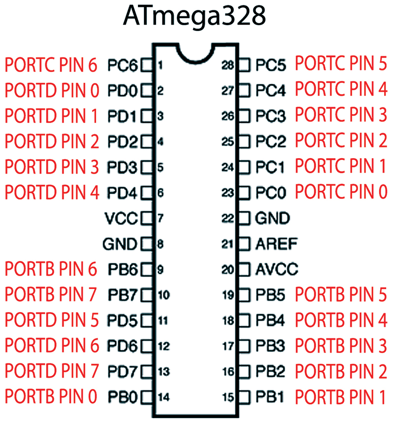
FIGURE 2. ATmega328 port pin mapping.
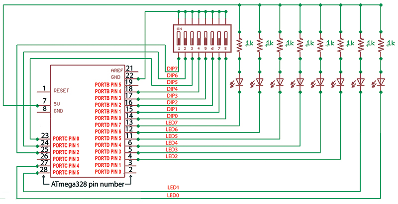
FIGURE 3. ATmega328 pins for DIP switch and LED.
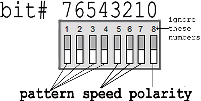
FIGURE 4. DIP switch use.
Getting Bit Fields From a DIP Switch
We will let the top four switches encode 16 patterns, the next lower three can encode eight speeds, and the lowest switch can encode the polarity. In order to look at each of these parameters individually (while ignoring the others), we use bit masks which are sets of bits set to 1 that we AND ‘&’ with the byte so that we exclude the other bits. This is best explained with an example:
// DIP switch masks<br />
#define POLARITYMASK     0x01    // 00000001<br />
#define SPEEDMASK        0x0E    // 00001110<br />
#define PATTERNMASK      0xF0    // 11110000
We have eight patterns and we can encode them with four switches, as follows:
Binary Decimal Pattern Select
0000    0       right_sweep1<br />
0001    1       right_sweep2<br />
0010    2       right_sweep3<br />
0011    3       right_sweep4<br />
0100    4       left_sweep1<br />
0101    5       left_sweep2<br />
0110    6       left_sweep3<br />
0111    7       left_sweep4<br />
1000    8       right_stack        <br />
1001    9       left_stack<br />
1010    10      right_ant<br />
1011    11      left_ant<br />
1100    12      inout<br />
1101    13      blinkin<br />
1110    14      brownian<br />
1111    15      random
[NOTE: For sweep 5, 6, and 7, just run sweep 1, 2, and 3 with the polarity reversed.]
If we AND each of these masks with the value we read on the DIP switch, we convert all the bits we aren’t interested in to 0 and leave those we are interested in as they were in the port. Suppose, for instance, that we set the pattern to left_stack (9), the speed select to six, and the polarity to one, we would see 10011011 (0x9B):
PORTB = 10011011 (0x9B)
       bit #    76543210<br />
       PORTB = 10011011 = 0x9B<br />
POLARITYMASK = 00000001 = 0x01<br />
    ———————————————————————<br />
         AND = 00000001 = 0x01
       bit #    76543210<br />
       PORTB = 10011011 = 0x9B<br />
   SPEEDMASK = 00001110 = 0x0E<br />
    ————————————————————————<br />
         AND = 00001010 = 0x0A
       bit #    76543210<br />
       PORTB = 10011011 = 0x9B<br />
 PATTERNMASK = 11110000 = 0xF0<br />
    ————————————————————————<br />
         AND = 10010000 = 0x90
To get the parameters using raw C, we would write:
uint8_t pattern = 0;<br />
uint8_t speed = 0;<br />
uint8_t polarity= 0;<br />
uint8_t dip_value = 0;
dip_value = get_dip();
// Using raw C bitwise operators<br />
pattern = ((dip_value & PATTERNMASK) >> 4 );<br />
speed = ((dip_value  & SPEEDMASK) >> 1 );<br />
polarity = dip_value & POLARITYMASK;
The only problem is that we have to remember where the field was in the mask so that we can remember to shift it the correct number of times. Or, we can give ourselves yet another bitwise crutch and write macros to get these parameters automatically so that we don’t need to remember so much. This crutch would let use retrieve the pattern, speed, and polarity without having to remember anything about the size and position of our bit fields:
// Using a function as a crutch<br />
pattern = get_mask_field8(dip_value,PATTERNMASK);<br />
speed = get_mask_field8(dip_value,SPEEDMASK);<br />
polarity = get_mask_field8(dip_value,<br />
   POLARITYMASK);
As is often the case, I owe a debt to the folks at www.avrfreaks.net for the macros we’ll use. I posted my concept and immediately was given a better way. (Michael Hennebry provided the algorithm, and I changed the macro names to conform to my process):
#define bit_to_shift8(mask) ( \<br />
((mask) & 0x01) ? 0 : ( \<br />
((mask) & 0x02) ? 1 : ( \<br />
((mask) & 0x04) ? 2 : ( \<br />
((mask) & 0x08) ? 3 : ( \<br />
((mask) & 0x10) ? 4 : ( \<br />
((mask) & 0x20) ? 5 : ( \<br />
((mask) & 0x40) ? 6 : 7 )))))))
#define get_mask_field8(byte, mask) \<br />
(((byte) & (mask))>>bit_to_shift8(mask))
This method allows the compiler to do some serious optimizing and according to another AVRFreak, Cliff Lawson, this wonder uses only four opcodes on an AVR!
If there is a down side, it is that this may well be one of the most complicated looking things we have seen so far. But if you’ll take some time with it, you should be able to follow what it is doing. First, the bit_to_shift8 macro finds the number of 0 bits to the right of a mask. For instance, for our PATTERNMASK 0xF0 // 0b11110000 we see that after we mask the DIP switch we need to shift the value four places to the right to get the numeric value of the pattern field. As you remember from algebra, when you work a problem with parenthesis you evaluate the innermost one first, then sequentially each next inner parenthesis until you get to the final outer parenthesis.
In the case of the bit_to_shif8 macro, the system first evaluates the expression: ((mask) & 0x40) ? 6 : 7 ). This looks at the second highest bit position and if it is 1, then the lowest bit found — so far — is the 0x40 bit, number 6; if not, then it is 7. Next, it looks at ((mask) & 0x20) ? 5 : ( X ). This looks at the third highest bit position and if it is 1, then the lowest bit found — so far — is the 0x20 bit, number 5; if not, then it is what we found in the previous evaluation (either bit 6 or 7). The next ((mask) & 0x10) ? 4 : ( \ does exactly the same as before and determines the lowest bit so far. This continues until each bit has been evaluated.
For the PATTERNMASK, the lowest bit is 0x01 and the shift is 4. For the SPEEDMASK, the lowest bit it 0x02 and the shift is 1. For the POLARITYMASK, the lowest bit is the lowest bit 0, so the shift is also 0. So for our pattern mask, the bit_to_shift8 tells us how many bits to shift right. We just AND ‘&’ our DIP switch value with our PATTERNMASK and shift it the four bits to get the number for the pattern.
I hope this is clear because if you understand it, you are getting fairly sophisticated in your understanding of C programming and bitwise operations. I also recommend rereading this section each night at bedtime if you have trouble falling to sleep (with this, you should find yourself nodding right off).
Okay, I’ve slipped off the rails again and run out of time and space (fortunately, gravity is still working), so if you want to see how this is used in a real chaser light application, you can get the source code at http://code.google.com/p/avrtoolbox in the sources under avr_applications\simple-chaser_lights.
Next time, we will finish our study of DIO by using it with an LCD navigator as shown in Figure 5. NV
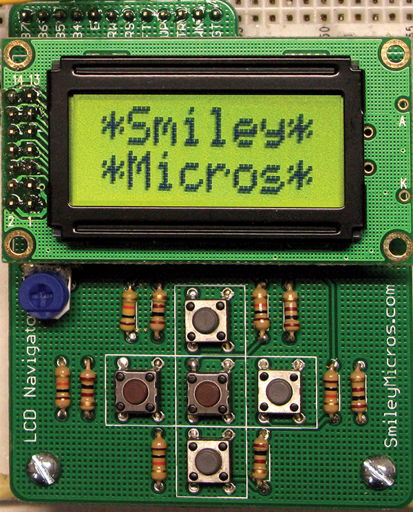
FIGURE 5. Next episode’s LCD navigator.
Theory is all well and good, but to really learn this stuff you have to get your hands on some tangible items that blink, whirr, and sometimes detonate. As a service for the readers of the Smiley’s Workshop articles, we have simple and inexpensive projects kits available that can help you make it real. You can find these kits (and some darn good books) at the Nuts & Volts Webstore.