The digitally-programmable potentiometer (DPP) is a mixed signal, system-level control device performing a component-level function. The potentiometer adds variability to the analog circuit, while the digital controls add programmability. The DPP brings the high speed, programming, computation, and control of a processor to the variation of the potentiometer in a wide array of analog applications.
Definitions and Block Diagrams
The potentiometer is a three-terminal variable resistance divider device whose schematic symbol is shown in Figure 1.

FIGURE 1. Schematic symbol of the potentiometer.
The potentiometer is a passive component and comes in two types: mechanical and electronic. The terminals of the problematic mechanical potentiometer are called CW (clockwise), CCW (counter clockwise), and wiper. The most common corresponding names or designations for the terminals of the electronic version are RH, RL, and the wiper RW. The high and low designations of the terminals are used for wiper direction purposes — the terminals are interchangeable. The mechanical pot is a three-terminal device, while the electronic potentiometer is an integrated circuit with a minimum of eight terminals.
The digitally-programmable potentiometer (DPP) is an electronic potentiometer whose wiper position is computer or digitally controlled. The electronic version of the potentiometer has a memory where wiper settings can be stored. The DPP is a system-level control device performing a component-level function — this idea is illustrated in Figure 2A. The implementation of the analog potentiometer in the mixed-signal integrated circuit is shown in Figure 2B.
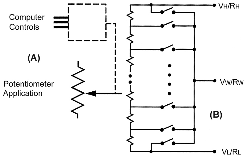
FIGURE 2. Digitally-programmable potentiometer.
(A) Mixed Signal (B) Potentiometer Implementation
Polycrystalline resistors are connected in series between the RH and RL terminals, and solid-state switches implemented by pMOS, nMOS, or CMOS transistors are connected at each end of this resistor array, as well as between the resistors. The switches are equivalent to a single pole, single throw switch. One end of all the switches are tied together and are connected to the wiper terminal. Only one switch will be closed at a time connecting a node in the series resistor array to the wiper. The resistors are polycrystalline silicon deposited on an oxide layer to insulate them from the other circuitry.
The Digital Controls
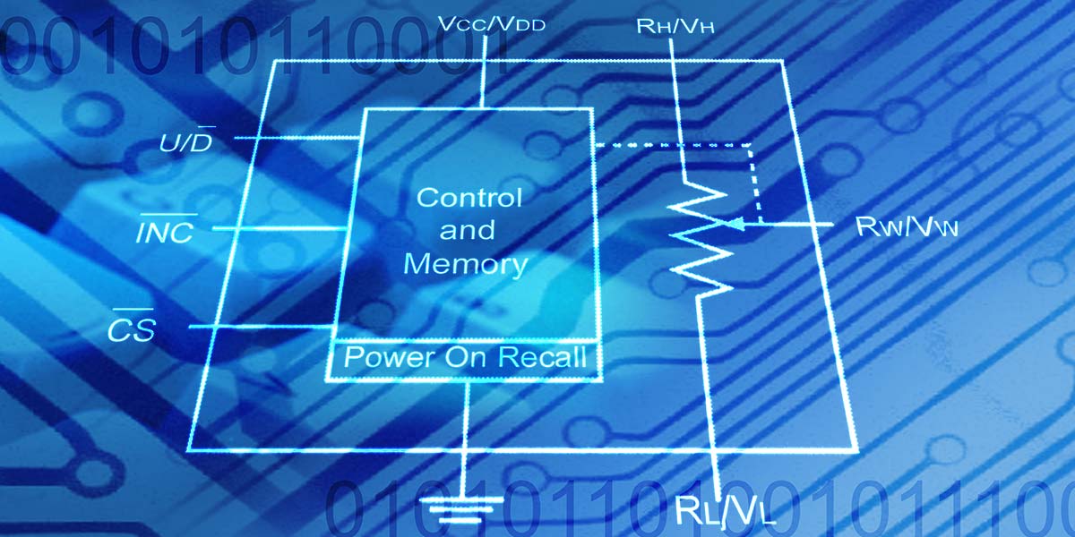
The block diagram of a typical DPP is shown in Figure 3.

FIGURE 3. Block diagram.
The control and memory section of the device is implemented in CMOS and is typically biased with a 3V or 5V (2.5V-6V) digital or logic supply. The device is controlled through one of several different serial buses. The more common serial buses are:
- Increment/decrement
- I2C
- SPI (Serial Peripheral Interface)
- Microwire-like
The control signals for the increment/decrement asynchronous bus are Up//Down, /Increment, and /Chip Select. The Up//Down control input is a level-sensitive signal which establishes the direction of the movement of the wiper. The wiper is moved on the falling edge of the Increment control input in the direction established by the Up/Down signal. The /Chip Select control input is like an address line and enables or disables the device. For the DPPs with an increment/decrement interface, there is only one internal nonvolatile register per potentiometer — the register stores the wiper setting for restoration during the power-up condition. The I2C, SPI, and microwire-like interfaces are synchronous and have protocols.
Basic Application Modes
The potentiometer can be used in application circuits as a three-terminal device or as a two-terminal device. The most common way to use the potentiometer as a three-terminal device — seen in Figure 4A — is as a voltage divider circuit. Plus and/or minus voltages are connected across the potentiometer and the wiper goes from one voltage limit to the other as the wiper is moved from the low to high terminals. In many applications, this circuit can be substituted for a digital-to-analog converter since it performs a digital in/analog out function. The variability of the wiper-to-low and wiper-to-high resistances of the potentiometer can be used to add variability to analog functions, like the non-inverting amplifier circuit shown in Figure 4B.
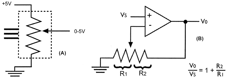
FIGURE 4. Basic applications — three-terminal device.
(A) Programmable Voltage (B) Programmable Gain
The second fundamental way of using the DPP is as a two-terminal, variable resistance. A simple application illustrating this configuration is shown in Figure 5A where the potentiometer functions as a variable resistor and, in essence, varies the current through the diode since the voltage across the potentiometer is relatively constant. The variation of R in Figure 5B allows the cut-off frequency of the high pass filter to be programmed. The two basic applications (Figures 4A and 5A) illustrate the use of the digitally programmable potentiometer in a digital-to-analog voltage circuit and in a digital-to-analog current circuit.
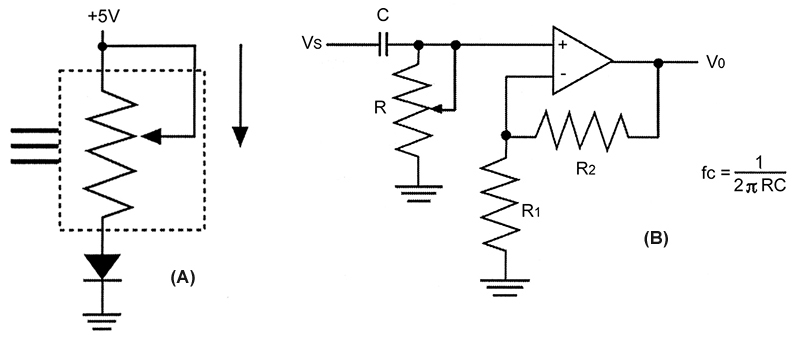
FIGURE 5. Basic applications — two-terminal device.
Circuit and System Level Applications
The DPP performs a basic component-level function and can be found in a very broad range of applications at both the circuit and system levels. Figure 6 lists some of these applications. DPPs control voltage, current, resistance, frequency, power, capacitance, bandwidth, Q, duty cycle, gain, etc.
CIRCUIT LEVEL APPLICATIONS
- Vary the gain of a voltage amplifier.
- Provide programmable DC reference voltages for comparators, window detectors, and limiters.
- Control the volume in audio circuits.
- Trim out the offset voltage and bias current errors in a voltage amplifier circuit.
- Set the output voltage of a linear voltage regulator.
- Control the passband gain, characteristic frequency, cutoff frequency, and Q in filter circuits.
- Set the scale factor and zero point in sensor signal conditioning circuits.
- Vary the frequency and duty cycle of timer ICs.
- Vary the DC biasing of a pin diode attenuator in RF circuits.
- Provide a control variable (I, V, or R) in closed loop, feedback circuits.
SYSTEM LEVEL APPLICATIONS
- Control the power level of LED transmitters in communication systems.
- Set and regulate the DC biasing point of power amplifiers in communication systems.
- Control the gain in audio and home entertainment systems.
- Provide the variable DC bias for tuners in RF systems.
- Set the operating points in temperature control systems.
- Control the operating point and linearization scheme for sensors in industrial systems.
- Trim offset and gain errors in artificial intelligent systems.
- Adjust the contrast in LCD displays.
FIGURE 6.
Wherever there is a resistance which defines a system parameter, the DPP becomes a candidate to vary and control that parameter. As an example, the DPP can be used to control the duty cycle of a PWM (pulse width modulator). The PWM, in turn, can be used to control the speed of a robot's motor, or it can be used as the key control element in a switching power supply.
For the designer, the electronic potentiometer is a superior component because it is digitally-controlled, programmable, flexible, and has a small size and low weight. In the manufacturing area, the electronic potentiometer is low-cost, reliable, compatible with automated assembly techniques, has a short test time, and has low field service costs.
The wiper-to-low and wiper-to-high resistances of the potentiometer, shown in Figure 7, are modeled as (kRPOT) and (1-k) RPOT, where k is a dimensionless number from 0 to 1 and reflects the proportionate position of the wiper from one end (k=0) of the potentiometer to the other end (k=1).
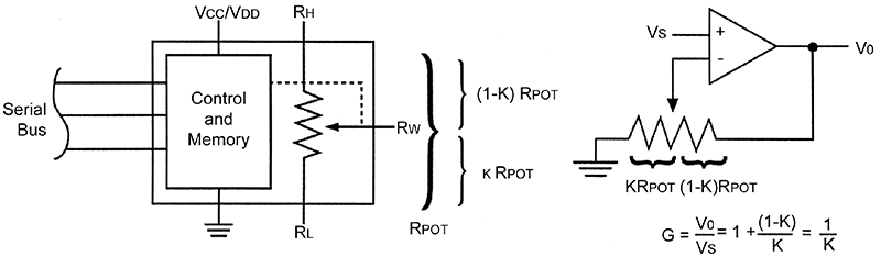
FIGURE 7. Modeling potentiometer resistance.
When analyzing analog circuits with potentiometers, k will show up in the defining equations of the circuits and provide another degree of freedom for the circuit designer. The potentiometer adds variability and programmability to the analog circuit, and k is a way of assessing the variability on the circuit's performance.
Data Sheet Parameters
The analog data sheet parameters reflect the limitations and characteristics of the digitally-programmable potentiometer. The key analog data sheet parameters are number of taps, end-to-end resistance, maximum voltages on the potentiometer pins, wiper resistance and current, resolution, noise, linearity, and temperature coefficients. Figure 8 lists the data sheet parameters and their values for a typical DPP.
CAT5114 POTENTIOMETER PARAMETERS
Symbol
| Symbol |
Parameter |
Conditions |
Min |
Typ |
Max |
Units |
| RPOT |
Potentiometer Resistance |
-10 Device |
|
10 |
|
kΩ |
| |
|
-00 Device |
|
100 |
|
|
| |
Pot Resistance Tolerance |
|
|
|
±15 |
% |
| VRH |
Voltage on RH pin |
|
0 |
|
Vcc |
V |
| VRL |
Voltage on RL pin |
|
0 |
|
Vcc |
V |
| |
Resolution |
|
|
3.2 |
|
% |
| INL |
Integral Linearity Error |
lw ± 2µA |
|
0.5 |
1 |
LSB |
| DNL |
Differential Linearity Error |
lw ± 2µA |
|
0.25 |
0.5 |
LSB |
| RWi |
Wiper Resistance |
Vcc = 5V, lw = 1mA |
|
|
400 |
Ω |
| |
|
Vcc = 2.5V, lw = 1mA |
|
|
1 |
kΩ |
| lw |
Wiper Current |
|
|
|
1 |
mA |
| TCRPOT |
TC of Pot Resistance |
|
|
TBD |
|
ppm/°C |
| TCRATIO |
Ratiometric TC |
|
|
TBD |
|
ppm/°C |
| RISO |
Isolation Resistance |
|
|
TBD |
|
Ω |
| VN |
Noise |
|
|
TBD |
|
nV/√‾Hz |
| CH/CL/CW |
Potentiometer Capacitances |
|
|
8/8/25 |
|
pF |
| fc |
Frequency Response |
Passive Attenuator |
|
1.4 |
|
MHz |
FIGURE 8. Datasheet Parameters.
The number of taps in a potentiometer reflects the resolution of the device or its ability to discern 1 of n. Potentiometers used in a summing amplifier circuit can extend the basic resolution of the pot to almost an unlimited number. The end-to-end resistance (RH to RL) of the potentiometer is RPOT and comes in 1kΩ to 100kΩ values. A low cost, low TC, one percent resistor in parallel with RPOT provides the designer with a technique of customizing the pot's end-to-end resistance in most applications. The voltage VCC/VDD, 2.5V to 6V, provides the voltage biasing for the digital control and memory section. The voltages VTERMINAL or VRH/VRL are the maximum voltages that can be applied to the potentiometer pins in their application. Wiper resistance models the resistance rds (on) of the MOS switches used to connect the wiper terminal to a node in the resistor array. The wiper current spec, 1-3mA, limits the maximum amount of current allowed through the wiper switches.
Application circuit topologies where the wiper is connected to a high impedance minimize the dependence on the wiper's specs. Absolute linearity describes the actual versus expected value of the potentiometer when used as a divider, and is guaranteed to be accurate within one least significant bit (LSB). Relative linearity describes the tap-to-tap accuracy and is guaranteed to be 0.5 of an LSB. Two parameters describe the temperature dependence of RPOT and the resistances in the series array. RPOT TC (temperature coefficient) is a nominal 300ppm/ºC and the ratiometric TC is guaranteed to be within 20ppm/ºC. While the data sheet parameters reflect the performance limitations of the digitally-controlled potentiometer, there are a large number of circuit techniques that minimize these limitations. Application notes and technical briefs describe these techniques and are available at On Semiconductor's website www.onsemi.com. NV