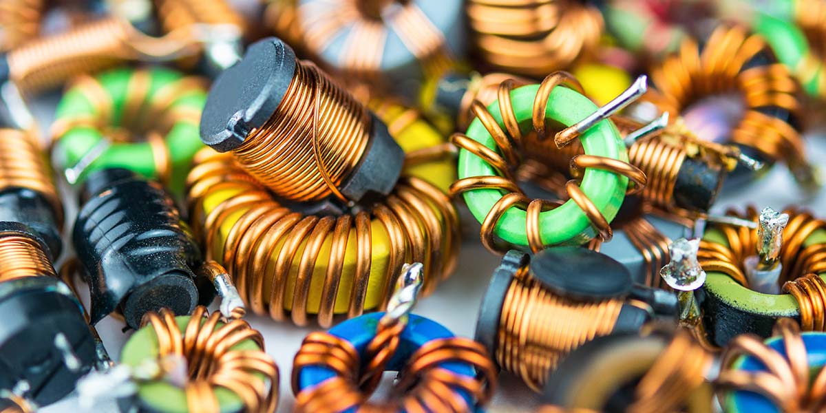
While resistors and capacitors are easily procured and stocked, most radio frequency circuits require inductors in a wide range of very specific values. In most cases, you need to create these yourself, by winding wire on ferrite rods or toroids of specific types and sizes. Is it possible to substitute another ferrite piece at hand and still get the right inductance value? How can a hobbyist measure inductance without buying an expensive instrument? This article describes the principle behind inductance and presents some tricks that I have used to make my own inductors.
Introduction
Resistors are the most common passive component on any printed circuit board (PCB), so it’s good that they cost just a little more than a penny each. Up in price an order of magnitude from resistors are capacitors, which are generally larger. Rare — except in radio frequency circuits — are inductors which are generally much larger than the capacitors, more expensive, and very hard to source.
Probably not a lot of folks have likely seen a memristor — the fourth passive component that completes the passive component family, as seen in Figure 1.
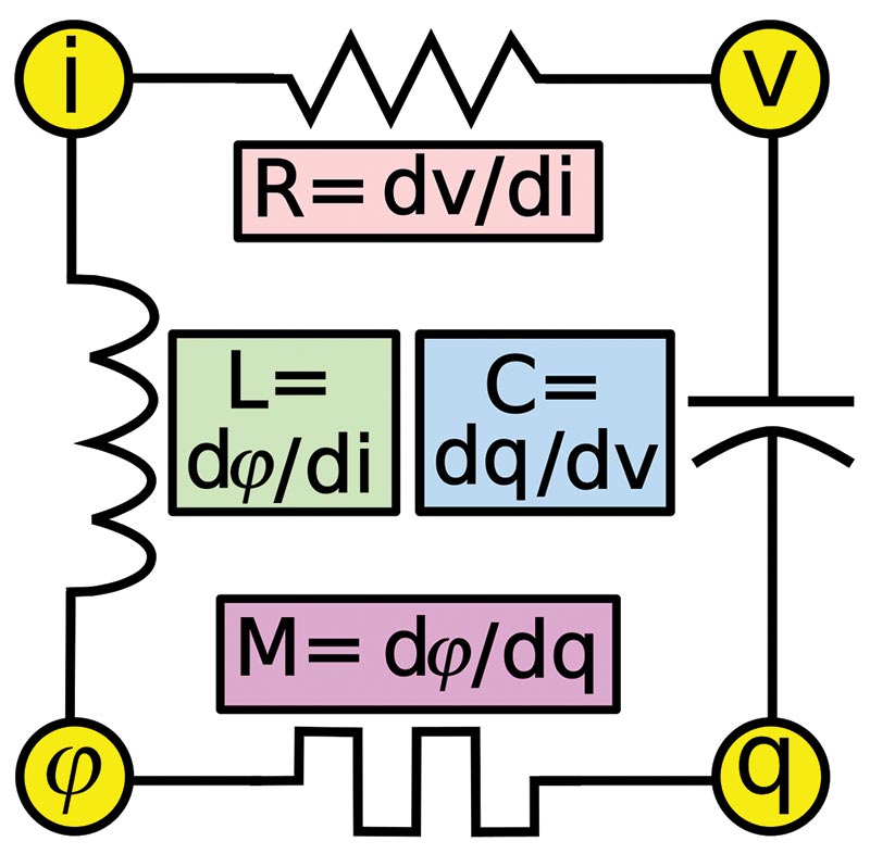
FIGURE 1. The four members of the passive components family: the resistor R; capacitor C; inductor L; and the memristor M. The component values are determined by their response to current i, voltage v, charge q, and magnetic flux φ.
Practical examples of the memristor have been developed only in the last decade.
History of Inductors
The unit of inductance is the henry, named after the American scientist, Joseph Henry (1797–1878). Henry was the first to wrap multiple coils of wire around a piece of iron to create an electromagnet that was more powerful than a solenoid coil with no iron core.
English scientist, Michael Faraday (1791–1867) — for whom the unit of capacitance, the farad, is named — did similar experiments at about the same time. Faraday discovered that an alternating current in one transformer winding will induce a current in another. Note the similarity between the words, “induce,” and “inductance.”
The Solenoid
The simplest inductor is a solenoid coil, which is just a helix of wire with no core (Figure 2).
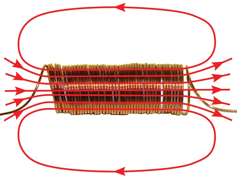
FIGURE 2. A simple air-core solenoid with its magnetic field lines shown.
Passing a direct current through a solenoid creates a magnetic force; a fact discovered in the early 19th century.
A solenoid essentially stores the electrical energy of flowing current in a magnetic field. When the core of the solenoid is empty, this energy is stored in the physical vacuum, also known as free space.
Since air has a low magnetic permeability, much of the magnetic field potential afforded by applied currents is lost, so the inductance is smaller than when a magnetic core is introduced (see Figure 3).
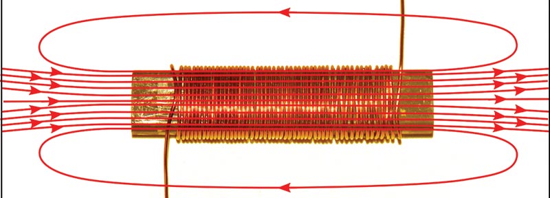
FIGURE 3. A solenoid coil wrapped on a ferrite core.
If our solenoid coil is very long, it’s inductance L is easily calculated:
L = N2μ0A/ℓ
where L is the inductance in henrys, N is the number of turns, μ0 is the permeability of free space (4π x 10−7 H/m), A is the cross-sectional area of the coil in square meters, and ℓ is the length of the coil in meters. This formula applies only to long single layer coils, but it’s generally close for shorter coils and most multi-layer coils, as I’ll show later.
If we wind a coil on a magnetic material (such as a ferrite rod), the inductance is greatly increased (Figure 3). That’s because the permeability of the core is much greater than the permeability of free space. The magnetic core concentrates the magnetic field lines inside the coil where they have the greatest effect.
Depending on the core material, the inductance increase can be much more than a thousand, although common radio frequency values range from about 200 for VHF to 1,000 for lower frequencies.
The magnetic permeability of ferrite is large, so the magnetic field lines are concentrated in the coil, thereby increasing inductance by a large factor.
The inductance equation for such a coil is the same as for an air-core coil multiplied by the relative permeability K of the magnetic core:
L = N2Kμ0A/ℓ
The relative permeability is the ratio of the permeability to the permeability of free space. The magnetic core can be moved into and out of a coil to make a variable inductor.
As an example that multi-layer coils closely follow this same equation, I measured the inductance of the 52-turn coil shown in Figure 3 and got 93 mH. When I put a second layer of 42 turns over this, the inductance was 315 μH. Scaling by the ratio of the square of the turns gives us a calculated inductance of 303 μH, which is just a few percent less.
Toroid
Magnetic flux “leaks” out of each end of a short solenoid coil, and that’s why the inductance equations given above are specified for the ideal case of an infinite length.
A simple fix for such leakage is to join the ends together to create a toroid, as shown in Figure 4.
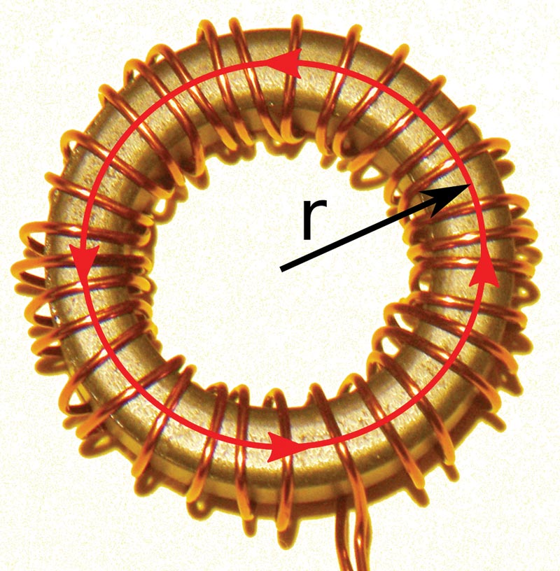
FIGURE 4. An inductor wound on a toroidal ferrite core.
The inductance of a single layer winding on a toroid is given as:
L = N2Kμ0A/2πr
which is our familiar equation with the length replaced by the unwrapped length of the toroid; that is, its circumference at the midpoint, with the distance from the center of the circle to the midpoint being the radius r.
Toroids offer a slightly greater inductance than short solenoids for the same number of turns, since the magnetic field lines are all contained inside the core.
Ferrite Materials
While iron is a magnetic material, it doesn’t make a good inductor core. That’s because it’s also an electrical conductor, and the alternating currents applied to a surrounding coil will lose energy by heating the iron through induced eddy currents. Think in terms of not putting metal objects into a microwave oven.
There’s also the problem that the iron will “saturate;” that is, become so charged with a magnetic field that it can’t be made to magnetize further.
There are various ways around this problem; one of which is to load the iron with silicon to form a steel alloy that’s less conducting, and to form the core from thin sheets that are insulated from each other. This is the method used to make cores for most low frequency transformers. Another is to make the iron into a fine powder and encapsulate each grain.
At radio frequencies, we need a better material than iron or steel; one that won’t saturate and is an insulator. Fortunately, materials scientists have discovered oxides of iron and other metals that satisfy these requirements. They are called ferrites, since they are based on the oxide, Fe3O4, called ferrite.
In most cases, some of the iron (Fe) is replaced by other metals; notably manganese, zinc, and nickel.
Quality Factor
You can’t wire your house with small diameter wire since the wire resistance is too high; you’ll get a voltage drop across that resistance. Too small a diameter wire will likewise diminish the effectiveness of an inductor, which ideally should have zero resistance at low frequencies.
The quality of an inductor — known as its Q — is a measure of how well it acts as a perfect inductor at a given frequency F:
Q = XL/R = 2πFL/R
where XL is called the inductive reactance (essentially, the “AC resistance”) which is equal to 2πFL. The Q factor effectively shows how much better an inductor is at responding to alternating current than direct current. It also shows how narrow a band-pass filter you can build from an inductor and capacitor.
Gyrators
Inductors and capacitors are complementary devices. Capacitors pass high frequencies while blocking low frequencies. A capacitor’s ability to block direct current is one of its most important functions.
An inductor quite differently passes low frequencies and blocks the high frequencies.
There’s an electrical circuit called a gyrator that uses a capacitor to make a simulated inductor. Gyrators are built around an amplifier. They can be implemented using active components, including transistors, but it’s most common to use an operational amplifier (op-amp) as shown in Figure 5. Gyrators can be used to simulate huge values of inductance, but they have a few limitations.

FIGURE 5. An op-amp gyrator circuit. RC forms a phase-shifting circuit, and the simulated inductance is proportional to this phase shift. The resistor RL must generally be at least a few hundred ohms for most op-amps, so the inductor Q is limited.
Op-amps generally work well only at low frequencies, so gyrator inductors will only work at low frequencies. As can be seen in Figure 5, the simulated inductance has one terminal grounded, so this limits the types of circuits in which gyrator inductors can be used.
Also, the inductor resistance RL must be reasonably large since op-amp inputs have limitations. RL must generally be at least a few hundred ohms for most op-amps, so the inductor Q is limited.
Litz Wire
The “skin effect” is the tendency for high frequency currents to preferentially flow near the surface of wire. In effect, the middle portion of the wire is wasted conductor at high frequencies; when you’re winding an inductor, you end up with a higher resistance for the same number of turns.
An easy way around this is to use Litz wire, which is a multi-stranded single-conductor wire. Litz wire allows a parallel combination of smaller wires that mitigates the skin effect.
Measuring Inductance
Digital multimeters that measure resistance, voltage, and current can be purchased at very low cost, and hobbyists typically have at least one of these in their tool chest. Inductance meters are more unusual and usually more expensive.
I don’t have an inductance meter, but I do have a signal generator and oscilloscope (as most dedicated hobbyists have), so I use a resonance technique to measure inductance (Figure 6).
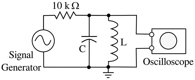
FIGURE 6. A resonant parallel combination of an inductor and capacitor driven by a signal generator and monitored by an oscilloscope.
A parallel combination of an inductance and capacitance is often called a tank circuit by old-timers since these circuits were often immersed in a tank of insulating oil in high power transmitters.
Such a circuit will resonate at a characteristic frequency F given by:
F = 1/(2π(LC)-1/2)
The resonance of the parallel LC circuit will be apparent by a peak in the voltage on the oscilloscope as the frequency is changed (Figure 7).
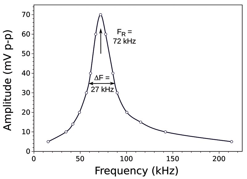
FIGURE 7. Frequency response of a resonant parallel combination of the toroidal inductor shown in Figure 4 and a 0.01 μF capacitor.
You don’t need to carefully graph the response (as in the figure) if you’re just interested in the resonance frequency.
The capacitor had a ±5% tolerance, so the calculated inductance could be accurate only to ±5%. If you have access to a capacitance meter, you can do better.
To determine the inductance, just parallel it with a known capacitance and plug the values into the equation.
The one caveat here is that capacitor values aren’t exact; they have a tolerance. The 0.01 μF capacitor that I used in the measurement shown in Figure 7 had a tolerance code J, which specified a not-ideal ±5%, but better than most.
This means that the calculated inductance can’t be any better than this. Some common capacitor tolerance codes are shown in Table 1.
| F |
±1% |
| G |
±2% |
| J |
±5% |
| K |
±10% |
| M |
±20% |
TABLE 1. Capacitor Tolerance Codes.
Reworking the resonance equation to give inductance yields the following:
L = 1/(4π2L2F2)
Based on the capacitor value of 0.01 μF and the observed resonance frequency of 72 kHz, the inductance for the coil shown in Figure 4 was 492 μH.
Plugging in values for the toroid relative permeability of 1,000, its cross-sectional area, radius, and number of turns into the toroid inductance equation gives 476 μH, or a deviation of about 3% — consistent with the capacitor tolerance.
Conclusion
Winding inductors can be an easy task when you know a few simple equations and measurement techniques.
Now that you know the basics, the Internet is a good resource for further information. NV