From Open Channel
The world is a really hostile place for electronic devices. Whether you use radio receiving and/or transmitting equipment, consumer electronics equipment, or electronic instrumentation, it is likely that you will experience electromagnetic interference (EMI) at some point. The stuff is all over the place!
Figure 1 shows some of the many, many sources of EMI in the normal residential or business building (industrial plants will have even more). A number of these sources have one thing in common: electrical arcing or sparking. Lightning, even when it is far enough away to be out of sight, can produce huge amounts of EMI. The lightning bolt may be either cloud-to-cloud or cloud-to-ground, and consists of about 250,000 amperes of current oscillating back and forth. Any arc produces a large number of harmonics. Indeed, selecting these harmonics was how the old spark gap transmitters (circa Titanic era) worked. Lightning will produce significant harmonic energy well into the high frequency (HF) region of the radio spectrum.
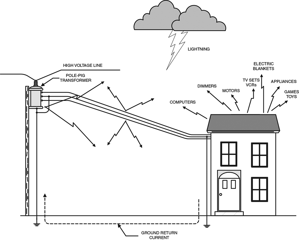
FIGURE 1.
Lightning also produces high voltage transients on the AC power lines. It does not require a direct hit for lightning to produce these transients. Any electrical current in motion relative to a conductor will induce an electromotive force (EMF) into the conductor. When a lightning bolt flashes anywhere nearby, or overhead, an EMF will be produced. When electronics were all analog these transients did not usually disrupt electronic circuits unless they were strong enough to create damage (many a silicon power supply rectifier has succumbed to lightning transients on the line). Digital circuits, on the other hand, can be severely disrupted by lightning transients.
The AC power lines are also a source of problems. The standard power system used in North America distributes power via high voltage lines operated against ground (see Figure 1). There may be several step-down transformers between your building and the power company generating station. There will be at least one transformer close by your building. It will either be buried or on a pole, as in Figure 1. The secondary of the transformer is center-tapped, with the center-tap grounded. The two ends of the transformer form a 240-volt service, while each end and ground form 120-volt services. All three lines are brought into the building.
Several forms of interference are associated with the AC power lines. First, of course, is the fact that there are significant 60 Hz electrical and magnetic fields surrounding the wires from the pole and the wiring inside the building. You can hear this noise when you touch a finger to the audio input of an amplifier hooked to a loudspeaker.
Another source of noise from the AC power lines is arcing. Loose connections are a source of noise problems and, like other forms of arcing, will produce harmonic energy a long way above 60 Hz. The power company will repair loose connections on power lines, but you must use an electrician to repair connections inside the building.
A number of appliances in the house will also produce noise. Anything with an electrical motor (air conditioner, refrigerator, furnace, heat pump, etc.) can produce arcing. The problem is at the brushes inside the motor. Like all other forms of arcing, the motor will interfere with circuits and devices operating well into the HF spectrum.
One class of device that can cause real havoc are those devices that operate using a silicon controlled rectifier or triac device. Examples include light dimmers, train speed controls, electric blanket controls, and so forth. These devices operate to control power by using only a portion of the AC sinewave cycle. In Figure 2, the shaded portion is the power actually applied to the load. The difference between high and lower power settings of the control is the percentage of the AC sinewave that is applied (as indicated by the shaded portion). Because the waveforms have a sharp cut-off and cut-on characteristic when power is stopped and started over the course of a cycle, harmonic energy is produced. Sometimes lots of it.
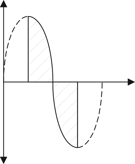
FIGURE 2.
Television sets and video cassette recorders (VCRs) are significant sources of EMI. There are three basic sources of EMI: vertical deflection circuits, horizontal deflection circuits, and the color circuits. The two deflection circuits use non-sine waveforms. The vertical operates at 59.94 Hz, while the horizontal operates at 15,734 Hz. The harmonics of both can cause problems with receivers and other devices, especially the horizontal deflection.
The color circuits of television sets use a phase reference at about 3.58 MHz. The EMI from the color phase circuits is especially strong from VCRs in the record mode. In my neighborhood, I can use my ham radio receiver to determine whether or not there is a popular movie on TV. The cacophony from the 3.58 MHz signals from all those VCRs tears up the 80-meter ham band.
Figures 3A and 3B show the time series and spectrum plots of about six seconds’ worth of signal recorded at my home. I used a 10-turn, six-inch diameter loop of wire connected to the shielded cable that goes to the microphone input jack on a cassette recorder. The site was near my computer desk, so EMI from both the receiver and the monitor was recorded. The recorded signal was then processed in Spectra Plus software to produce the time and frequency series shown in Figures 3A and 3B.
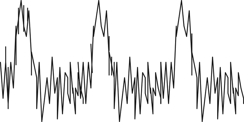
FIGURE 3A.
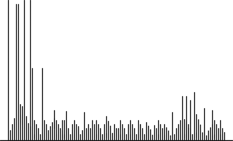
FIGURE 3B.
Especially notice the spectrum in Figure 3B. This is a spectrum plot, so shows lines representing frequencies, while the height of the line represents the strength of the signal. There is a huge concentration of energy around 60 Hz (left side of graph), with significant spikes at numerous frequencies out past 3,800 Hz. Because of the raucous noise on my Drake R-8A receiver, especially when it is tuned to the AM broadcast band, I suspect that significant harmonics at least go into the medium wave segment of the spectrum.
Tools for Finding EMI Sources
Rule 1: The correct tool for finding RF sources is anything that will permit you to unambiguously determine where the radiation is coming from. We will take a look at several low-cost possibilities.
If you are looking for a source that is out in the neighborhood somewhere, such as a loose power line or a malfunctioning electrical system in another building, then an ordinary solid-state portable AM BCB radio receiver may do the trick. Open the radio and locate the loopstick antenna. If you rotate the radio through an arc where the loopstick is first broadside to the arriving signal, and then perpendicular to the signal, you will notice a tremendous reduction in signal. Ferrite loopsticks are extremely sensitive to direction of arrival, with a sharp null occurring off the ends.
By noting the direction in which the null occurs (Figure 4), you find the line of direction to/from the signal source. It is not unambiguous, however. To find the actual direction, from the two possibilities that are 180 degrees opposed, move along the line and note in which direction the signal increases. Except in a very few cases where reflections occur, the signal will become stronger as you move towards the source.
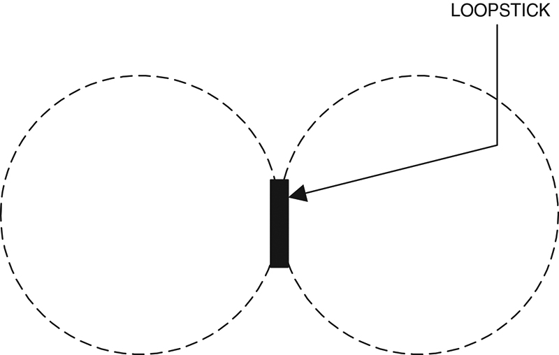
FIGURE 4.
The standard mediumwave and shortwave loop antenna used by a lot of radio enthusiasts is also useful for finding RF emitting sources. A square loop of 10 to 24 inches to the side is relatively easy to construct, and forms a very directional antenna. These antennas are commonly used in radio direction finding. Such loop antennas offer a null when pointed broadside to the signal direction, and a peak when orthogonal to the signal direction.
A portable radio with an S-meter will work wonders in this respect. An ad-hoc signal strength meter (“S-meter”) can be formed using the circuit in Figure 5. This circuit plugs into the earphone jack of the receiver. The received audio is rectified by D1/D2 (a voltage doubler), and then ap-plied to a DC current meter. Because resistor R1 (sensitivity control) is in series with M1, it operates as an analog voltmeter.
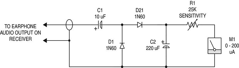
FIGURE 5.
If the noise peaks in the HF shortwave bands, then the radio’s loopstick is of little use (it only works on the MW and LF AM BCBs). The HF antenna in those receivers is a telescoping whip. You can, however, make an external loopstick sensing antenna. A seven-inch ferrite rod is wound with about 20 turns of fine enameled wire. This wire is connected to a coaxial cable, that is, in turn, connected to the external antenna terminals of the receiver (if such exists). If there are no external antenna terminals, then a small coil of several turns wrapped around the telescoping antenna will couple signal to the radio. It’s a good idea to keep the antenna at minimum height in order to minimize pick-up from sources other than the loopstick. More sensitivity can be had if a resonant loopstick is available, but those also restrict the frequency band.
Two coil sensors are shown in Figure 6. The sensor in Figure 6A is a solenoid-wound inductor connected to a length of coaxial cable. The coil has a diameter of about one to three inches, and a length that is at least its own diameter. The coil consists of two to 10 turns of wire, depending on frequency (the higher the frequency, the fewer the turns required). The other end of the coaxial cable is connected to a receiver. When the coil is brought nearer the noise source, the signal level in the receiver will get higher.
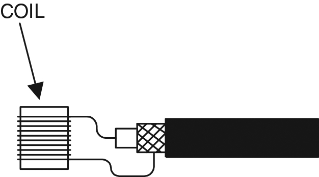
FIGURE 6A.
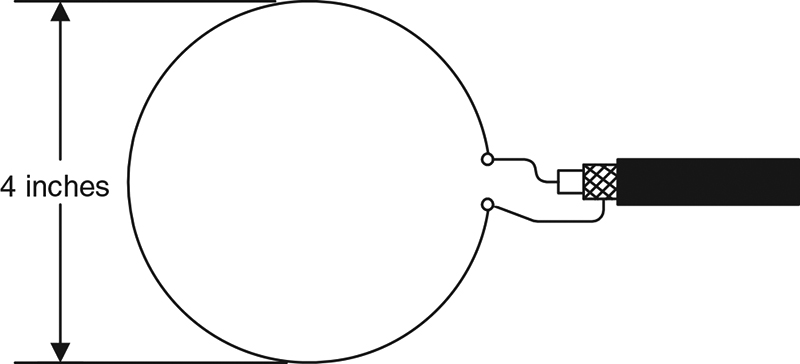
FIGURE 6B.
A single-turn “gimmick” is shown in Figure 6B. This sensor consists of a single loop, approximately four inches in diameter, connected to coaxial cable. It can be used well into the low end of the VHF spectrum, as well as at HF. The loop is made of either small diameter copper tubing, heavy brass wire or rod, or heavy gauge solid copper wire (#10 AWG or lower). The loop has some directivity, so can be used to ferret out extremely localized sources.
A fault with the single-turn loop is that it is somewhat sensitive to magnetic fields, although not so much as some of the other forms. Figures 7A and 7B show dual-loop sensors that are less sensitive to magnetic field pick-up. In Figure 7A, the loops of the sensor are rectangular and crossed in the center. The feedline (coaxial cable) is connected to a break in one of the two coils.
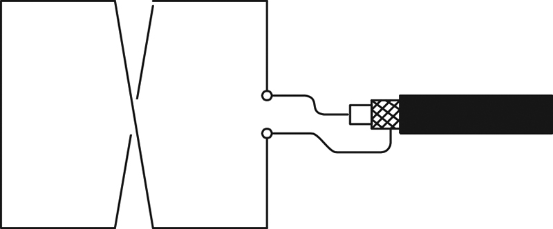
FIGURE 7A.

FIGURE 7B.
The version shown in Figure 7B is circular. One version that I built was made of #8 AWG solid copper wire formed around a tin can. Getting the coils about the right size and reasonably circular is relatively easy given a proper former. The exact size of the coils in Figures 7A and 7B is not terribly important. The coil should not be too large, however, or it will be less local and may become a bit ambiguous in locating some sources.
RF Detectors
The RF output of the sensor coils can be routed to a receiver, and for low-level signals may well have to be so treated. For higher power sources, however, an RF detector probe is used. Figures 8 and 9 show two forms of suitable RF detector probe.
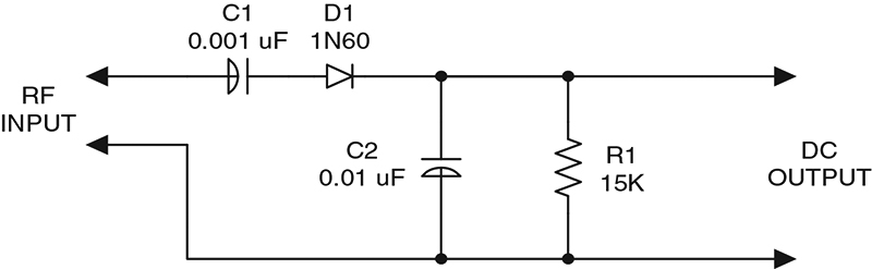
FIGURE 8.
The RF detector in Figure 8 is passive, i.e., it has no amplification. It can be used around transmitters and other RF power sources. The input from the sensor is applied to C1 — a small value capacitor — and then is rectified by the 1N60 diode. The 1N60 is an old germanium type diode, and is used in preference to silicon diodes because it has a lower junction potential (so is more sensitive). The junction potential of Ge devices is 0.2 to 0.3 volts, and for silicon it is 0.6 to 0.7 volts. The pulsating DC from the rectifier is filtered by capacitor C2. Resistor R1 forms a load for the diode and is not optional.
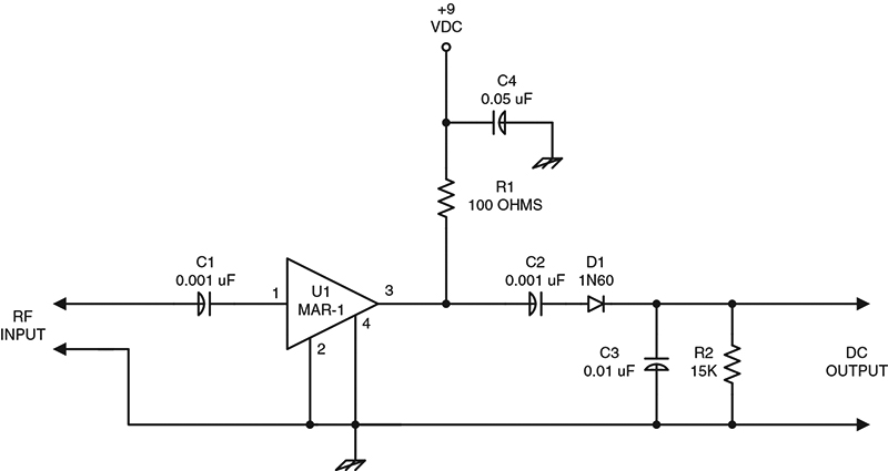
FIGURE 9.
An amplifier version of the RF detector circuit is shown in Figure 9. In this version, the same RF detector circuit is used, but it is preceded by a 15 to 20 dB gain amplifier. In this particular circuit, the amplifier is a Mini-Circuits MAR-1 device. It produces gain from near-DC to about 1,000 MHz. Other devices in the same series will work to 2,000 MHz, and in the related ERA-x series up to 8,000 MHz. Clearly, any of these devices are well suited to the needs of most readers. The cost of the MAR-1 device is very low (in the USA it is about $3.00 in unit quantities). NV
For Further Reading
ARRL Radio Frequency Interference: How To Find It and Fix It. American Radio Relay League, 225 Main Street, Newington, CT 06111. You can order via the web site: www.arrl.org.