I built the electronic stethoscope to help find a noise in my car. It is hard to find such noises without some type of listening aid. I have also used it to find noises in moving parts of electronic and other equipment. Another use, that I did not think of when building it, is checking the operation of speaker systems.
Historically, the first listening aid (for automobiles) was an acoustic stethoscope, similar to a medical acoustic stethoscope except for the sound pickup (actually a vibration pickup). A metal probe connected to a diaphragm is used. The back of the diaphragm is enclosed, and flexible tubes connect it to metal earpieces. The probe is placed in contact with suspected sources of noise, and vibrations conducted by the probe to the diaphragm are converted into sound waves which travel through the tubes to the earpieces.
An electronic stethoscope can be a considerable improvement over an acoustic stethoscope. It is more sensitive, has better frequency response, and has a volume control to reduce the level when the noise is loud.
Several electronic units are sold by automobile parts and equipment suppliers, and several construction articles have been published in electronics publications.
In these units, the noise is picked up by a probe, then amplified and sent to headphones. Most of them use a small microphone element in the probe which picks up sounds from the air; a few use a vibration probe.
With a microphone, the probe does not have to contact the noise source. As it is brought near the source of noise, the sound in the headphones gets louder. For some noises, a microphone probe is better. For others — for example, a noisy alternator bearing — a vibration probe is better.
When I needed to find a noise in my car, I looked at several published stethoscope circuits. Most of them used several parts or required high-impedance headphones. Some required a split power supply. I had recently built some circuits using the LM386 power amplifier IC, and I decided a simpler, better stethoscope could be built using it.
My circuit uses a single LM386 and a few other parts, operates from a single nine-volt battery, and drives standard stereo headphones with more than adequate volume. Not only are stereo headphones easier to find (most of us have some extras lying around), their wide frequency response gives better reproduction of low-frequency noises than most high-impedance headphones.
In some published stethoscope circuits, stereo headphones are used, but the headphone units are connected in series to increase their impedance for adequate volume.
A series connection drives the headphones out of phase, which may produce an odd sound. The electronic stethoscope has more than adequate power and gain with the headphones connected in parallel (producing more natural in-phase sound from the headphone units).
Several stereo headphones were tried, all of them provided higher volume than is needed. Both types of probes — a microphone probe and a vibration probe — are included, for use with different types of noises.
Circuit Description
The LM386 power-amplifier IC is used in the electronic stethoscope. A number of circuits have been published using the LM386, one of the most useful, readily available guides is the LM386 data sheet in Radio Shack’s Semiconductor Reference Guide.
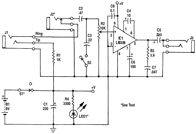 |
| Figure 1. In the stethoscope amplifier, IC1 has a voltage gain of 200. |
In the electronic stethoscope circuit (shown in Figure 1), the LM386 operates at its maximum voltage gain of about 200; R2 is the volume control. (In circuits using the LM386, if C4 is omitted, the gain is about 20 and bypass capacitor C6 is not needed. Intermediate gains can be obtained by connecting a resistor in series with C4; 1200 ohms gives a gain of about 50.)
R3 and C7 improve high-frequency stability of the amplifier. In building several different circuits using the LM386, power supply bypass capacitor C8 has been very important in assuring a stable amplifier. It should be located close to IC1 (within one or two inches on the board). Some published circuits for the LM386 do not use it, but one circuit I built was very unstable until it was added.
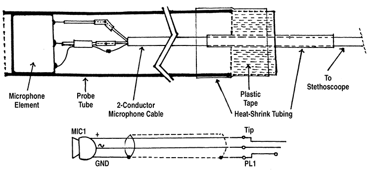 |
| Figure 2. The Microphone Probe. |
Battery operation is possible because the quiescent current of IC1 is about 5 mA. For low battery drain, LED1 — the pilot light — is a low-current type, which draws only 2 to 2.5 mA. C3 and S2 form a treble-cut tone control, useful when looking for a low-frequency noise. The microphone element in the microphone probe (Figure 2) is connected directly to the input of the amplifier.
A piezo element is used as a pickup transducer in the vibration probe (Figure 3). When used as a sound source, a piezo element cannot produce low frequencies, because of the small size and stiffness of the vibrating element. However, when used as a pickup, it has a fairly good low-frequency response. (Similarly, the small diaphragm of the microphone could not produce low frequencies, but it is effective in picking up low frequencies.)
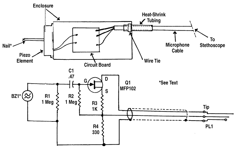 |
| Figure 3. The Vibration Probe. |
Because of its effective internal series capacitance of 0.025 µF, the piezo element (BZ1) must be connected to a circuit with a high input impedance for good low-frequency response. If it was connected directly to the amplifier input, the 10,000 ohm resistance of R2 would cause the low frequency response to roll off at 6 dB per octave below about 640 Hz.
In the circuit in Figure 3, Q1 is used as a source follower. Its high input impedance eliminates low-frequency roll off; its gain is slightly less than one. The output of the vibration probe is still higher than the output of the microphone probe; R3 and R4 form a voltage divider to reduce the output.
The impedance matching circuit of Figure 3 is located in the probe to eliminate noise pickup in the shielded cable. (High-impedance cables pick up noise unless they are very well shielded, and there is lots of noise around a car engine!)
Construction
The circuit was built on one section of a RadioShack 276-159 Dual IC Project Board. (I have found this board to be useful for many small projects, using one IC, two small ICs, or several parts but no ICs.) Not all of the board is used and it is possible to cut off one or two edges of the board (with a fine-tooth hacksaw) to make it a better fit in the case.
A RadioShack 270-239 metal case (left over from an earlier project) was used. A plastic case could probably be used, as the shielding of a metal case does not seem to be necessary; there is little hum or noise pickup in the amplifier. R2, S2, J1, J3, and LED1 were all mounted in one end of the case, allowing the case to be placed in a pocket or clipped to the user’s clothing.
The two-conductor shielded microphone cables to the probes are about four feet long. Probe jack J1 is a miniature (1/8”) stereo phone jack. This could cause a problem, as output jack J3 is also a stereo phone jack. I tried to find a different connector for J1, but could not find a three-conductor connector that is small enough to fit in the end of the case.
I used a regular (1/4”) jack for J3, both to make it different from J1 and to allow large headphones to be used, since most large headphones have a 1/4” plug. (An adapter is used for headphones with a 1/8” plug.) R1 was added to prevent shorting B1 if headphones are accidentally plugged into J1.
If a different connector is used for J1, R1 can be omitted. (The supply voltage rating of MIC1 is 4 to 10 volts; it can be supplied directly by B1.)
J2 was added to allow the amplifier to be used separately — such as an audio signal tracer — when needed. It was mounted on the side of the case, as there was not room on the end.
S2 can be replaced by a 10,000-ohm pot, for a variable treble-cut tone control. In my unit, there was not room in the end of the case for another pot (S2 is smaller). If a pot is used, you may want to change C3 to 0.47 µF or larger, for more high-frequency reduction at the maximum cut setting.
There are several sources for low-current LED1 (2 to 2.5 mA) used for a pilot light. A red low-current LED is sold by RadioShack (stock number 276-044). QT Optoelectronics low-current LEDs are available from Digi-Key Corp. (701 Brooks Ave. South, P.O. Box 677, Thief River Falls, MN 56701-0677, phone 1-800-344-4539) as stock number HLMP-4700QT-ND (red) and HLMP-4719QT-ND (yellow).
(The current rating of these is not shown in recent Digi-Key catalogs, but was shown in earlier catalogs, and I used these LEDs in my stethoscope and in several other battery-powered projects.)
Hewlett Packard No. HLMP-4700 (red) is available from Hosfelt Electronics, Inc. (2700 Sunset Blvd., Steubenville, OH 43952, phone 1-800-524-6464), as stock number 25-325. Other low-current LEDs, available from various distributors, include those manufactured by Lumex Optoelectronics, Inc., Industrial Devices, Inc., Chicago Miniature Lamps, and Linrose Electronics, Inc.
I built the microphone probe in a metal “faucet supply tube” (used in plumbing). This has an outside diameter of 3/8”, expanded to about 1/2” at the end which attaches to the faucet. The expanded end, which is partially closed, was drilled out to 3/8” diameter to fit MIC1. The tube is longer than needed for the probe, and can be cut to a suitable length (about 4” to 6”).
A plastic faucet supply tube is also available (it probably could be used), as well as a higher-priced “flexible” metal tube, which probably would not work as a probe housing.
If you have trouble finding a faucet supply tube, a straight metal or plastic tube, 3/8” inside diameter, can be used.
Construction of the probe using a straight tube is shown in Figure 2. The shielded cable is spliced to the short cable attached to the microphone element. Then the microphone element is mounted, with a small amount of glue, near the end of the probe tube.
Strain relief must be provided where the cable leaves the probe, to prevent pulling on the microphone or on the splices. The strain relief I used is also shown in Figure 2.
First, a 2-1/2” to 3” length of heatshrink tubing is placed over the cable (this is easier if it is done before the microphone element is mounted in the probe). Then, after the element is in the probe, the cable is wrapped with 3/4” plastic electrical tape to a diameter just smaller than the probe tube.
About 2” of 1/2” heatshrink tubing is placed over the plastic tape and the probe tube to hold them together. (If desired, the heatshrink tubing can extend over the entire length of a metal probe tube to protect against shorts if the probe is dropped.)
The circuit and construction of the vibration probe is shown in Figure 3. An encased piezo element is used as a vibration transducer. It is fastened to the end of a small project box with plastic glue or Super Glue™.
A standard four-penny (1-1/2”) nail is used as the vibration pickup. It is glued to the center of the piezo element, extending through the hole in the element case. The glue would be strong enough to hold the nail to the element, but not so strong as to tear the metal coating on the element if there is a blow to the nail. Super Glue or epoxy glue are probably best.
The nail, next to the head, was built-up with 3/4” electrical tape and heatshrink tubing to the diameter of the hole in the element case, to (hopefully) protect against a blow to the nail. (After the nail in my unit was loosened by a blow, I made a carrying case for the vibration probe from a small shipping box. Plastic foam was cut to shape and glued in the box to hold the probe in place.)
If the head of the nail is not smooth, it should be smoothed with a file. If the nail head is larger than the hole in the piezo element case, the edge of the head can be filed to a smaller diameter, or the hole in the element case enlarged (very carefully).
The impedance matching circuit (Q1 and associated parts) was built on a small perforated board and mounted in the probe enclosure. Q1 can be an MPF102, 2N3819, or similar small JFET. Note that the gate is lead 3 on a MPF102, and lead 2 on a 2N3819.
On these and many other small JFETs, the source and drain are interchangeable. To provide strain relief, a length of heatshrink tubing (about 2”) was placed on the probe cable where it leaves the enclosure. Then a wire tie was tightened over the heatshrink tubing inside the enclosure until the tie would not slide on the cable (see Figure 3).
Testing and Operation
Connect the microphone probe and turn on the amplifier. At higher volume settings, sound should be heard in the headphones if the probe is near any source of sound. There may be a feedback howl if the probe is brought close to the headphones.
To use the stethoscope, bring the probe close to suspected sources of noise. The sound in the headphones will get louder as the microphone probe is brought closer to the noise source. If you have trouble locating the source, switch to the vibration probe.
For example, a noisy alternator bearing produced similar noise levels with the microphone probe when the probe was near any part of the alternator. But when touching both ends of the alternator with the vibration probe, the end with the bad bearing was noticeably louder.
The microphone probe can also be used for checking stereo speakers. Good quality headphones should be used, preferably large-size units with a cushion which reduces external sounds. Hold the probe a few inches in front of each tweeter, mid-range, and woofer unit.
Any noise, distortion, weak sound, etc., can be heard in the headphones when the probe is in front of the defective unit. If in doubt, compare with the sound from the speaker for the other channel.
You can also do a rough check of the dispersion angle of a tweeter by holding the probe at different angles and positions in front of the tweeter. NV
AMPLIFIER PARTS LIST (Figure 1)
SEMICONDUCTORS
IC1 - LM386 audio amplifier, integrated circuit
LED1 - Low-current LED (see text)
RESISTORS (1/4-watt, 5% or 10%)
R1 - 1,000 ohm
R2 - 10,000 ohm audio taper panel-mount potentiometer, with switch (Radio Shack 271-215 or
similar)
R3 - 3.9 ohm
R4 - 3,300 ohm
CAPACITORS
C1, C5 - 220 µF, 16 WVDC, electrolytic
C2 - 0.47 µF, ceramic disc or Mylar
C3 - 0.22 µF, ceramic disc or Mylar
C4 - 10 µF, 16 WVDC, electrolytic
C6 - 100 µF, 16 WVDC, electrolytic
C7 - 0.047 µF, ceramic disc or Mylar
C8 - 0.1 µF, ceramic disc or Mylar
OTHER COMPONENTS
J1 - Miniature (1/8”) stereo phone jack (see text)
J2 - Closed circuit mono phone jack (optional, see text)
J3 - 1/4” stereo phone jack (see text)
S1 - Power switch (part of R2)
S2 - SPST miniature slide or toggle switch
B1 - Nine-volt alkaline battery
MISCELLANEOUS
Enclosure (see text), circuit board (Radio Shack 276-159 or similar, see text), stereo headphones, nine-volt battery snap with leads, knob, wire, solder, hardware, etc.
MICROPHONE PROBE PARTS LIST (Figure 2)
MIC1 - Electret microphone element (Radio Shack 270-092 or similar)
PL1 - 1/8” stereo phone plug (see text)
Small two-conductor shielded cable (Radio Shack 278-514 or similar), “faucet supply tube” or 3/8” ID tubing (metal or plastic, see text), heatshrink tubing, plastic electrical tape, wire, solder, etc.
VIBRATION PROBE PARTS LIST (Figure 3)
RESISTORS (1/4-watt, 5% or 10%)
R1 , R2 - 1 megohm
R3 - 1,000 ohm
R4 - 330 ohm
OTHER COMPONENTS
Q1 - MPF102 or similar JFET
C1 - 0.47 µF, ceramic disc or Mylar capacitor
BZ1 - Encased piezo element (Radio Shack 273-073 or similar)
PL1 - 1/8” stereo phone plug (see text)
MISCELLANEOUS
Enclosure (Radio Shack 270-220 or similar), small two-conductor shielded cable (Radio Shack 278-514 or similar), four-penny (1-1/2”) nail, small perforated board, heatshrink tubing, small wire tie, wire, solder, etc.