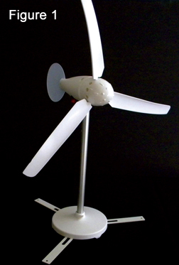
 Like our Whirlybird™ wind turbine, the WindPitch has a small but powerful three-phase AC alternator and variable pitch blades (thus the name). The blades are actually designed to aircraft standards, so it is a superb electrical and mechanical teaching tool. Horizontal axis wind turbines (HAWTs) are currently the standard wind technology mechanism for grid-based electrical generation. You see them everywhere — generally with three blades that slowly rotate into the wind to make non-polluting power. What you don’t see from a distance are the myriad factors that go into modern HAWT design and construction. That’s what I want to show you now with the WindPitch, so let’s get started.
HAWT and VAWT Technologies
Previously, we worked with the Whirlybird wind turbine which is a VAWT (vertical axis wind turbine). The WindPitch is a HAWT since the axis of rotation of the propeller blades and the alternator shaft are parallel — or horizontal — to the ground. Unlike the Whirlybird, the WindPitch blades produce “lift” just like an aircraft wing or propeller (which is also a set of wings itself). This provides for a faster spin rate of the blades with the attendant increase in generated alternator power. Compare this with the “drag” blades of the Whirlybird that are basically pulled around by the wind with no speed amplification.
There is also the ability to adjust the pitch of the blades to match the particular wind conditions. Wind is generally of higher speed at higher altitudes (even just a hundred feet or so off the ground), so the ability to control the pitch angle of the blades into the wind becomes important. Modern commercial wind turbines can quickly adjust the blade pitch to accommodate slowly varying wind speeds, as well as sudden wind gusts or lulls. This is done to extract the maximum electrical power from the wind for any given condition and to protect the wind turbine from damage should it encounter a sudden wind blast that could send it spinning out of control (even momentarily).
Another thing a HAWT needs is a wind vane to keep the propellers pointed into the wind at all times. However, commercial wind turbines are generally installed into the prevailing wind to begin with, and use more sophisticated electronic and mechanical techniques to constantly adjust for minor changes in wind direction so a vane is not necessary. The WindPitch does have the traditional vertical wind vane.
A HAWT is typically mounted on a tower — unlike a VAWT that is generally mounted on the ground. The advantage of this is that the wind is stronger and steadier at higher altitudes and doesn’t suffer from surface interface that can both slow the wind speed and create turbulence. The drawback is that the tower itself must support all the weight of the turbine assembly, along with the forces generated by the spinning blades — not to mention its own weight and air resistance. The tower is also an obstruction to the laminar wind flow that can cause the blades to momentarily lose power and slow down as they rotate parallel to the tower. When spinning, this causes a pulsing action like a misfiring engine cylinder that disturbs the smooth blade turning action and imparts additional mechanical stresses on the whole thing.
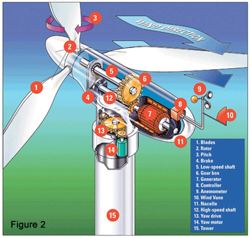 The important thing to understand here is that the HAWT is now the commercial standard for “big wind” grid-based operations, mainly because the cost-performance ratio is higher than with an equivalent VAWT to generate the same electrical power. You will, of course, see successful examples of vertical axis machines for small wind applications for which they are perfectly suited (like for a house or small buildings; see the sidebar). Just like the choice between AC and DC electricity, one isn’t necessarily better than the other, and each variety of wind turbines (vertical, horizontal, or hybrid) has its own niche and should be viewed in terms of choice of application as opposed to better or worse. For the remainder of this section, refer to Figure 2 for an example of the major components that go into a commercial HAWT.
 The WindPitch in a Nutshell
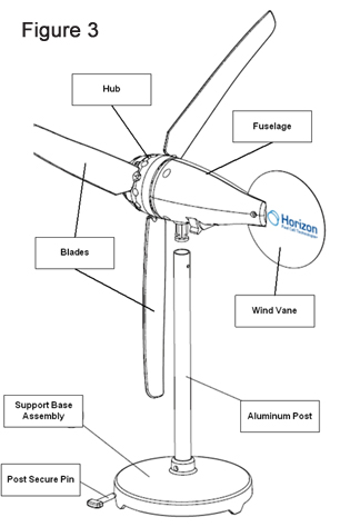
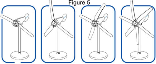
Figure 3 shows the major components of the WindPitch wind turbine. Generally, it consists of a three-blade propeller arrangement mounted to a hub where the blades can be manually adjusted for pitch by the hub mechanism (Figure 4). The hub then “pushes on” to the shaft of the three-phase alternator that is mounted at the inside-front of the streamline fuselage plastic housing. The hub along with the blades can be removed to change blade types; there can be anywhere from two to 12 blades (Figure 5).
The vertical wind vane is mounted at the opposite end of the fuselage to keep the blades pointed into the wind. The entire assembly is mounted on an aluminum pipe whose opposite end is inserted into a weighted base to keep the turbine steady with wind blowing across the blades. The small tab that protrudes from the bottom of the fuselage and inserts into the top of the pipe allows it to “wiggle” back and forth in a yawing motion to capture the changes in wind direction, while a small set screw holds it to the pipe so it doesn’t fly away.
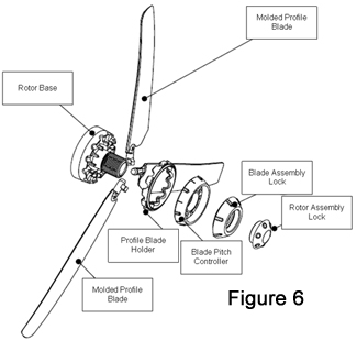
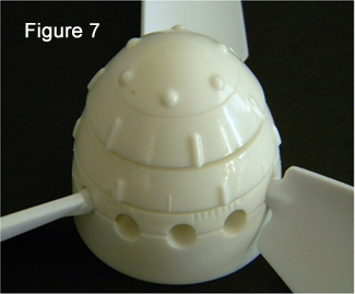
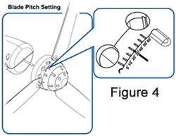 The most distinctive feature is the hub (Figure 6) that is designed to accommodate up to twelve blades and can also adjust the blade pitch. Once the blades are mounted into the hub, you are able to adjust the blade pitch simply by rotating what is called the Blade Pitch Controller. A clockwise/counter-clockwise turn rotates the blades to a new pitch angle (Figures 4 and 7), and then another couple of twists of the Blade Assembly Lock and Rotor Assembly Lock secure the new pitch angle in place. Overall, this is a well thought out device from top to bottom and is a pleasure to work with.
Blade Characteristics
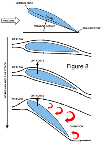
The fundamental element that is different from our Whirlybird wind turbine is that the WindPitch sports actual aircraft-type blades that provide lift that “pulls” them into the wind, as opposed to being “pushed” around by it. The blades are — in effect — really wings with the same characteristic shape of an aircraft wing. As seen in Figure 8, a wing deflects the air moving past it such that the upper part of the airflow generates a lower pressure, as compared with the lower part thus imparting “lift.” However, the question still remains, “How is lift created?”
 This from the well-known Bernoulli Principle and the lesser known Coanda Effect (see the sidebar) where air tends to follow a curved surface as long as the curvature isn’t too exaggerated or the “angle of attack” (the steepness of the blade edge as it is presented to the moving wind) isn’t too great. If either happens, the laminar (smooth) airflow is disturbed and turbulence is created that can lead to a stall.
Propeller blades exhibit the same lifting and stalling characteristics as fixed aircraft wings. Helicopters are a prime example of propeller blades that are really rotating wings where blade shape and pitch control the motions of the machine. However, in our case we are using the moving wind to spin the blades instead of powering the blades themselves; the effect, however, is still the same. Lift is generated to help power the blades in their spinning motion and, thus, impart more power to the three-phase alternator.
Blade Types
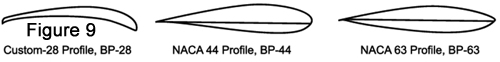
The WindPitch comes with three groups of distinct blades that are designated as BP-28, NACA 44, and NACA 63 types. NACA stands for the National Advisory Committee for Aeronautics which was created in President Woodrow Wilson’s days. In 1958, they were absorbed by (the then new) NASA – the National Aeronautics and Space Administration. The older acronym-based blade descriptions still remain to this day.
 As I mentioned earlier, the WindPitch is not a toy, and the adherence to these blade standards is one example of its rigorous nature. Figure 9 illustrates the profiles of each of the three blade shapes that are generally distinguished by the amount of material used on their windward sides. Time and space limit any further discussion regarding airfoil shapes and characteristics; however, our experiments will demonstrate how each profile has its own set of behavioral characteristics that make it suitable for varying wind conditions.
 Hub Assembly
As Figure 6 illustrates, a great deal of thought was devoted to the multi-part hub that holds the blades and allows them to swivel. Adding from one to 12 blades is possible, including mixing and matching different blade types. One begins by selecting the blades of choice, then placing them in the Rotor Base, followed by holding them in place with the Profile Blade Holder. The other three parts of the hub assembly (the blade pitch controller, blade assembly lock, and rotor assembly lock) are then screwed onto the Rotor Base forming a completed assembly as shown in Figure 7. By partially unscrewing the rotor assembly lock, you can adjust the blade pitch and then lock it in place again (Figure 4).
Blade Pitch
Besides blade shape and the number of blades used, blade pitch is right up there on the list for how to best generate power based on wind speed. Blade pitch or simply pitch refers to adjusting the angle of attack of the blades of a propeller into or out of the wind to control the production or absorption of wind power. The hub allows up to a 90 degree pitch angle. For reference, a zero degree pitch angle [with the flat part of the blades parallel to the wind] is called the “stall angle.” In effect, the blades are acting as a complete barrier to the wind in this position. The other extreme is with the blades at a 90 degree angle with only their leading edge facing the wind. This is called furling or feathering, and presents the minimum surface area to the oncoming wind.
Blade pitch control is a feature of nearly all commercial horizontal-axis wind turbines. While operating, a wind turbine’s control system adjusts the blade pitch to keep the rotor speed within operating limits as the wind speed changes. Feathering the blades stops the rotor during emergency shutdowns or whenever the wind speed exceeds the maximum rated speed. During construction and maintenance of wind turbines, the blades are usually feathered to reduce unwanted rotational torque in the event of wind gusts.
In an aircraft blade, pitch is usually described as “coarse” for a high angle of attack and “fine” for a low angle of attack. The same is true for wind turbines. Blade pitch is normally described in units of distance/rotation (assuming no slip) and is much like the gearing of a car’s transmission. Low pitch yields good low speed acceleration, while high pitch optimizes high speed performance and economy. Because the velocity of a propeller blade varies from the hub to the tip (called Tip Speed; see the sidebar), the blade must be formed correctly in order for the pitch to remain constant along the length of the blade.
Number of Blades
Since most commercial wind turbines use three-blade propellers, you might automatically assume that three blades are the optimum number. In fact, the number of blades is a compromise based — once again — on wind conditions and aesthetics. The number of blades involves design considerations of aerodynamic efficiency, component costs, system reliability and aesthetics (see the sidebar). In addition, noise emissions are affected by the location of the blades upwind or downwind of the tower, and the speed of the rotor. Given that the noise emissions from the blade’s trailing edge and tip vary by the fifth power of blade speed, a small increase in tip speed can make a huge difference.
Wind turbines developed over the last 50 years have almost universally used either two or three blades. Aerodynamic efficiency increases with the number of blades, but with diminishing return. Increasing the number of blades from one to two yields a six percent increase in aerodynamic efficiency, whereas increasing the blade count from two to three yields only an additional three percent in efficiency. Further increasing the blade count yields minimal improvements in aerodynamic efficiency and sacrifices too much in blade stiffness as the blades become thinner. We will do some experiments on this to confirm if the WindPitch exhibits behavior close to these same efficiencies.
System reliability is also affected by blade count, primarily through the dynamic loading of the rotor into the drive train and tower systems. While aligning the wind turbine to changes in wind direction (yawing), each blade experiences a cyclic load at its root end depending on blade position. This is true of one, two, three blades, or more. However, these cyclic loads when combined together at the drive train shaft are symmetrically balanced for three blades, yielding smoother operation during turbine yaw. Turbines with one or two blades can use a pivoting teetered hub to nearly eliminate the cyclic loads into the drive shaft and system during yawing.
Finally, aesthetics can be considered one of the biggest factors in determining blade count, since most people find the three-bladed rotor is more pleasing to look at as opposed to a one or two bladed rotor. All these are reasons why modern wind turbines use three blades.
 The Three-Phase Alternator
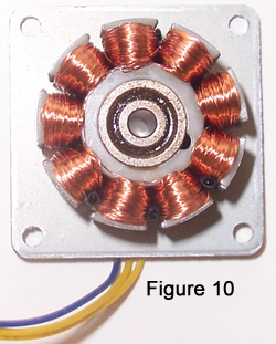
Switching from blade theory and design to the WindPitch power plant, I mentioned at the beginning the WindPitch uses a three-phase alternator (Figure 10) rather than a simple DC motor. The primary advantages of alternators are no commutator and increased power output due to the three-phase architecture (refer to Part 7 for background on three-phase versus single-phase advantages).
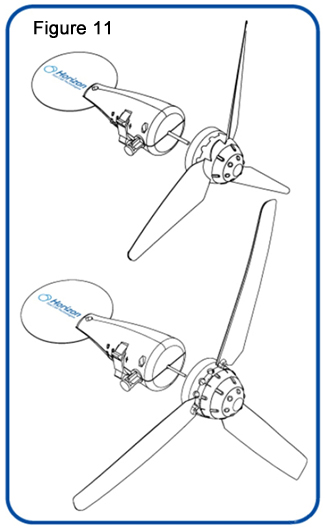 The alternator is permanently wired in the STAR configuration, so I won’t be able to do any STAR versus DELTA comparisons, but with a three-phase alternator ALL the electrical power is delivered directly to the rectifier circuit with nothing lost through the mechanical and electrical resistance of a commutator. In the WindPitch, the alternator is inserted inside the plastic fuselage with its shaft protruding from the front and attaching to the rotor hub (Figure 11).
The Full Wave Rectifier Circuit Board
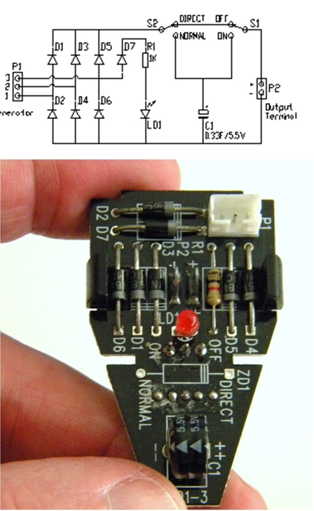
The three wire output of the three-phase alternator is connected to a six diode, full wave rectifier board (Figure 12) that converts the three-phase AC voltage into unfiltered DC. This is the exact circuit that I showed you with the Whirlybird in Part 7 where you learned about the advantages of three-phase full wave rectification and how a three-phase full wave rectifier works. The rectifier diodes are mounted on a triangular circuit board that fits behind the alternator; the rectified DC output is available on two (positive and negative) spring-loaded connectors. Suffice it to say that the WindPitch wind turbine delivers a very powerful electrical output for its model size which, of course, is dependent on the wind applied to the blades. We will get into this in our experiments.
Wrap-Up
The experiments I have planned for the WindPitch will take another article to complete. The goal of this article was to introduce you to the theory and operation behind HAWT technology; so in that regard, here is a list of factors that affect the HAWT power output:
-
Blade Swept Area: This was described in Part 7 with the Power Formula. Refer back to determine how to compute this value with the given blade area. I’ll cover it again in our next article when we experiment with the WindPitch.
-
Blade Shape: This provides the aerodynamic lift that pulls the blades into the wind instead of just having the wind drag them around.
-
Blade Pitch: This is the angle that’s best for startup and for maintaining optimum power output under varying wind conditions.
-
Number of Blades: This determines the overall efficiency coupled with performance of the turbine.
-
Wind Vane: This keeps the blades pointed directly into the wind at all times.
-
Three-Phase Alternator: This is significantly more powerful and efficient as compared with a DC commutator-based motor.
-
Tower Height: This is important in capturing smoother wind for better laminar flow across the blades which improves power output.
Next time, I’ll demonstrate some interesting experiments using the WindPitch. So, until then conserve energy and “stay green.” NV