With the wild fluctuations in fuel prices over the years, world concern over global warming, and simply the idea of creating new and more sustainable technologies, immense interest and progress continues in the world of battery development.
In fact, it seems that we keep hearing about a new breakthrough, and another step closer to that long sought elusive goal of a truly workable battery storage system. Perhaps one day soon we’ll have a battery that displays no “memory” effect, one that can be completely discharged or overcharged without harm, and require no complex computerized management system. This battery could even prove so durable it will be immune to damage from vibration and not break down chemically over time. In operation, such a battery might even routinely outlast the very vehicle or machine it was designed to operate in! Last, we could complete our wish list by adding in the impossible: low materials toxicity, simple construction, and, of course, good energy density.
Does such a battery sound like too much to hope for?
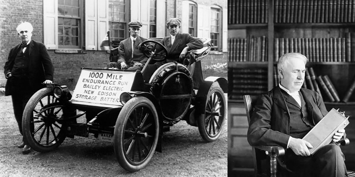
Thomas Edison didn’t think so when in 1899 — working with a design pioneered by Waldemar Jungner — he patented a battery with all these characteristics.
It was Edison’s hope that electric vehicles — which currently had the lead in popularity — would easily trump internal combustion or steam to be the vehicle of choice of his time, and ours. The Edison cell had a greater energy density than popular lead acid, and recharged in half the time. Astoundingly, it was not harmed by being fully discharged (even if dead shorted for years), and overcharging occasionally was actually good for the cell. It was even recommended as a monthly exercise in the battery’s manual!
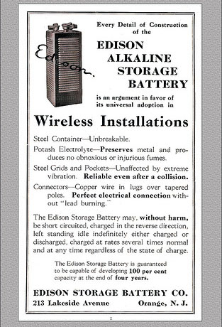
An old Edison advertisement.
Edison advertised that the cell had a life of at least four years, but the materials proved to be so stable (due to the low solubility of the reactants in the electrolyte) that some are still producing their full capacity today after more than 50 years! Problems with the Edison cell were few, and included poor performance at low temperatures, a high self discharge rate when unused (20% to 40% per month), and a slower than normal charge and discharge rate (65%). Yet, the practical nature of these cells was undeniable, and perhaps remains so today.
Like many overlooked gems throughout the history of engineering, perhaps these “diamonds in the rough” deserve a second look and some thoughts as to how our present technology could be improved by examining the principles of their operation. Many times historically these cells have been referred to as “the battery that worked too well.” Though they were popular and profitable in niche markets for Edison, it has been said that a business model could never be created for the general public by producing a product that does not require replacement. However, these days where “going green” is more than a quaint idea, perhaps Edison’s idea has finally found its time.
Constructing an Experimental Edison Cell
Because I know first hand the ingenuity and depth of knowledge of Nuts & Volts readers, I’d like to present the Edison cell to you in two ways. First, I’d like to briefly cover the historical construction of the cell. I think this will spark some ideas and even possible improvements to the cell. Then, I’d like to present the details of my own homemade cell experiments so you can construct one, as well.
Principles of Construction
In many ways, the remarkable Edison cell is functionally the opposite of batteries we use today. Edison used simple iron (anode) and nickel (cathode) screens for the electrodes, submerged in a potassium hydroxide electrolyte. Next, he bucked the popular methodology and rather than a strong acid, used an alkaline electrolyte (potassium hydroxide) for his cell. The basic chemical reaction can be written as:
2 NiOOH + 2 H2O + 2 e¯ « 2 Ni(OH)2 + 2 OH¯
Fe + 2 OH¯ « Fe(OH)2 + 2 e¯
(Discharging is read left to right; charging is from right to left.)
An alkaline electrolyte proved to be not only effective but — unlike acid — the solution was protective of the metal electrodes in the battery, giving them their phenomenal lifespan. The alkaline solution was also safer than acid, being about the same toxicity as ordinary bleach. (The raw chemical potassium hydroxide is not so benign, and must be handled with care as we’ll see later in an experimental cell.)
Edison claimed that he would not begin actual manufacturing of the cells unless he achieved five times the capacity of the competing (lead acid) cell. At one point, he claimed to have reached 15 times the energy density of lead acid in a series of remarkable experiments.
Edison had found the cell’s capacity increased directly with the surface area of the plates. It’s hard not to wonder with today’s astounding capabilities in miniaturization (and nano machines) what might be possible for plate creation with such robust cells.
Edison Cell: the Electrodes
A cutaway of an actual Edison battery is shown in Figure 1. Edison’s battery had alternating plates with metal “packets” which contained nickel II hydroxide (Ni (OH)2) for the positive plate, and the iron oxide (Fe3 O4) for the negative plate. In later designs, Edison used perforated tubes for his anode (as seen in this particular cell), instead of packets to hold nickel oxide for the positive plate.
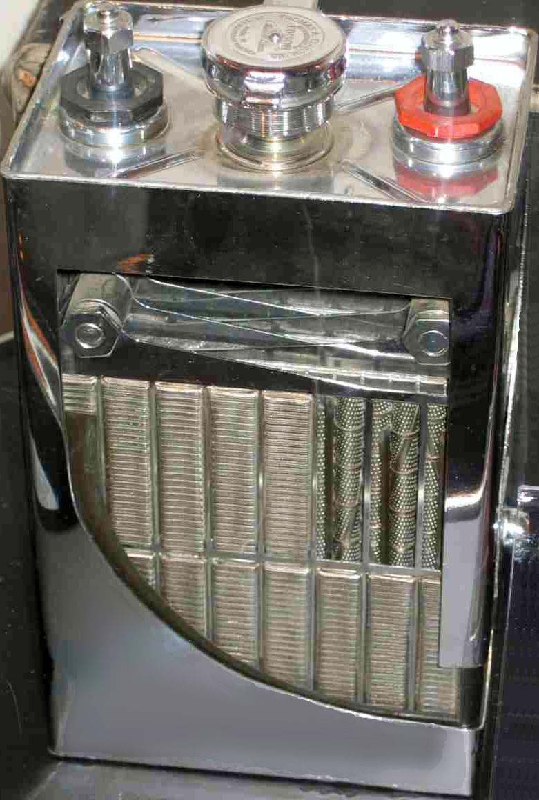
FIGURE 1. Edison Cell cut-away.
Photo courtesy of John DeArmond
Nickel II hydroxide is a very poor conductor, so in order to make electrical contact with it Edison used 32 layers per centimeter of alternating nickel flake and nickel II hydroxide inside the nickel tubes (as shown in Figure 2). So, the positive electrode works by allowing electrolyte in through the perforations in the nickel tube when submerged, and the nickel tubing and nickel flake make contact with the nickel II hydroxide to pass the charges back and forth. Each 10 cm of 6.3 mm (1/4 in) tubing will produce a full 1.25 Ah capacity!
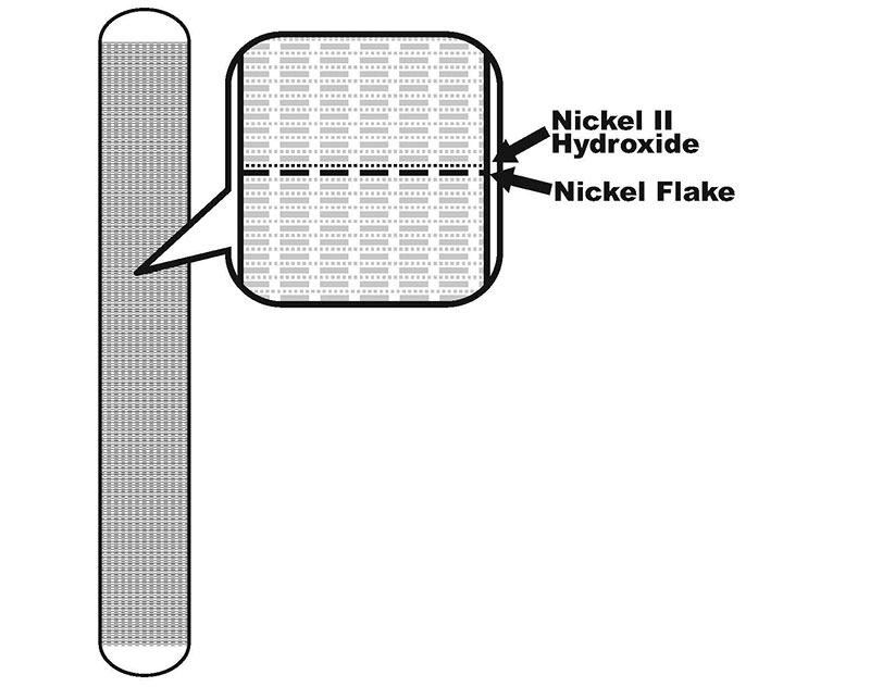
FIGURE 2. Anode cut-away showing layers.
Forming the negative electrode requires only filling tubes (or nickel plated metal packets) with the pure iron oxide (Fe3 O4) under pressure. (This essentially forms little iron oxide briquettes held inside the packets.) Gassing in the cell increases when the negative electrode is charged. So, the negative electrode is typically 30% larger than the positive electrode. This serves to minimize gassing inside the cell because the cell reaches full charge before the negative electrode reaches capacity.
An Experimental Cell
An experimental cell can be easily constructed on your workbench, and many of the cell’s characteristics can be seen and measured first hand. In fact, for a very simple science fair type project a 10 cm square plate of nickel screen and a similar plate of iron will have enough oxides naturally on them after a few charge cycles to light a low power LED for about 12 minutes when charged (Figure 3). Though such a cell has a minute capacity, it’s still interesting as a proof of concept experiment, and it recharges very rapidly making a nice science fair display.
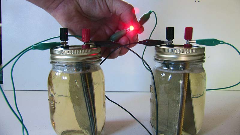
FIGURE 3A. LED run from simple nickel/iron plate battery.
It’s also very interesting that an ultra simple cell of this kind may well have an indefinite lifespan. This might be useful for a millennium project in conjunction with a solar cell for maintaining an ultra low drain memory circuit or some such thing for decades. However, for an interesting and useful project for Nuts & Volts, we want to get more capacity in our cell than that!
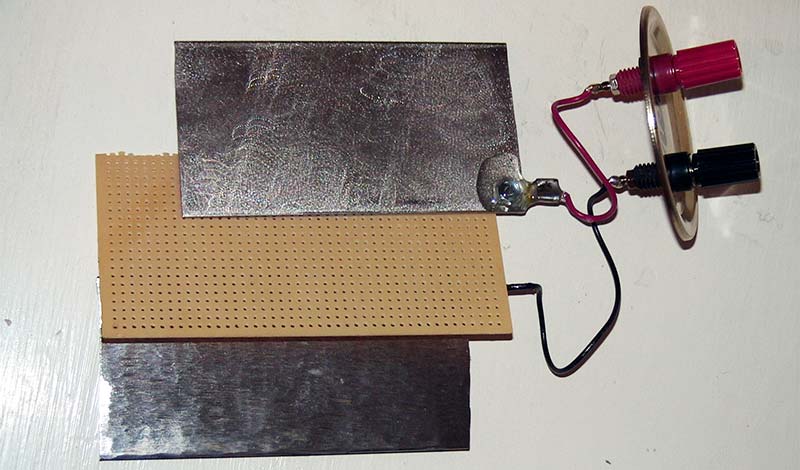
FIGURE 3B. Plates and separator from the battery shown n Figure 3A.
For that, you’ll need to procure a small quantity of both nickel II hydroxide and the iron oxide (Fe3 O4), as well as some powdered potassium hydroxide (KOH) for your electrolyte. Chemical supply houses will stock these items.
As an alternative source, I’ve also found pottery supply houses use oxides of both nickel and iron as colorants in pottery, and are far less expensive than chemical suppliers (see Sources).
eBay is an excellent source for potassium hydroxide because it’s currently used in making homemade bio diesel and soap. Important note: I have successfully used nickel III oxide instead of nickel II hydroxide for my positive electrode with excellent results. It’s cheaper, seems to work better, and is much easier to find.
Forming Your Electrodes
A simple idea I had for increasing capacity in our homebrewed cell was to literally use a conductive glue to attach the oxides to the outside of the electrodes. This gives a very high surface area “sandpaper” like finish to the electrodes, which is exactly what we want.
The electrodes themselves need to be nickel, or nickel plated. It’s very important to remember in your own designs that virtually any material other than nickel will corrode rapidly in this type of cell under the electrical action.
Your plate size can be anywhere from 10 cm square to a little over 50 cm square and still fit easily in a mason jar. It is certainly possible to greatly increase this size with multiple plates or even a standard “jelly roll” battery construction. Figure 4 shows this jelly roll construction of a NiCad battery.
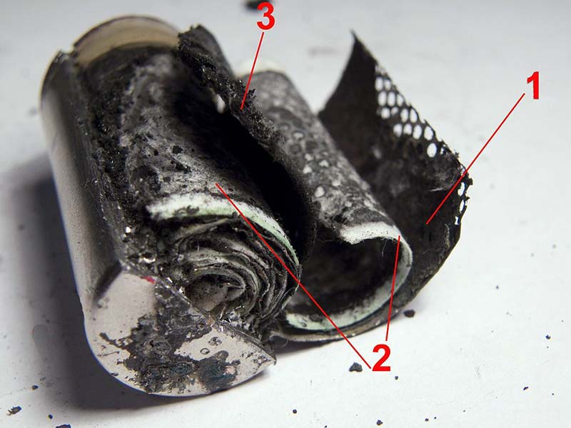
FIGURE 4. Disassembled NiCad: 1. Cathode plate. 2. Separator. 3. Anode plate.
Of course, your plates must not touch each other in the cell, so you may need to use a permeable non-conductive separator. This is actually a big topic, but for an experimental cell, it’s possible to use layers of fiberglass screen (available at any hardware store).
For my own simple cells (pictured), I soldered some solid copper wire to a fine copper screen (I think copper foil or plate would work, as well). I coated the solder connection with epoxy, and then nickel plated the screen.
Next, I simply coated the screen with a very thin layer of conductive epoxy (it goes a VERY long way if spread thin). (Conductive epoxy can be found in both nickel bearing and silver bearing.)
Last, I sprinkled and pressed powdered nickel oxide into the wet glue for my positive plate, and iron oxide for my negative plate. The results can be seen in Figure 5.
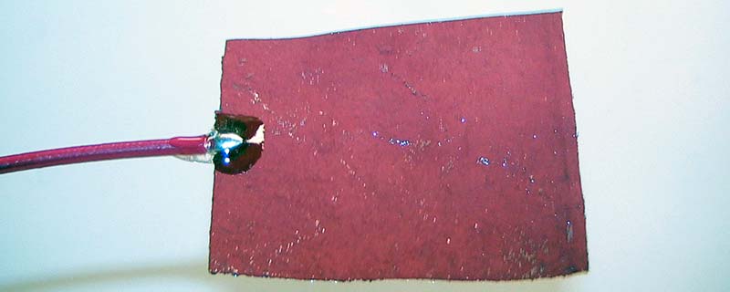
FIGURE 5. Homemade plate.
Though I’m not certain what the actual longevity of using epoxy to hold oxides to the plates will be, my test cells are now more than a year old and have been charged daily from solar cells without problems. So, mark this method as seems to work but, of course, is still experimental.
I’m certain that other methods of making contact with the oxides in solution will occur to you, so feel free to experiment!
Mixing Your Electrolyte
Begin by mixing a 20% solution (by weight) of potassium hydroxide and distilled water in a pyrex beaker. Keep in mind while doing so that potassium hydroxide should be added slowly to the water; never the other way around. Potassium hydroxide will react exothermically and some heat will be generated.
Gloves and goggles should always be used, and proper ventilation kept in mind. Raw potassium hydroxide powder should be handled carefully. It is caustic enough that it will cause burns if left in contact with your skin over a period of time. So, take reasonable care.
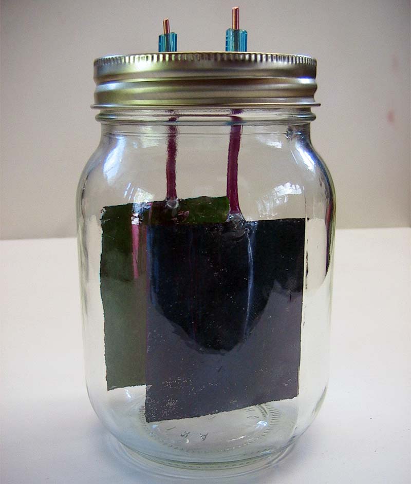
FIGURE 6A. Plates mounted in cells.
Fill the mason jar with the potassium hydroxide solution, keeping the level well below the lid; screw the lid on the jar. An assembled cell with both plates is shown in Figure 6A, and a shot of the separate plates in Figure 6B. (Remember, you can use larger plates than shown for greater capacity.)
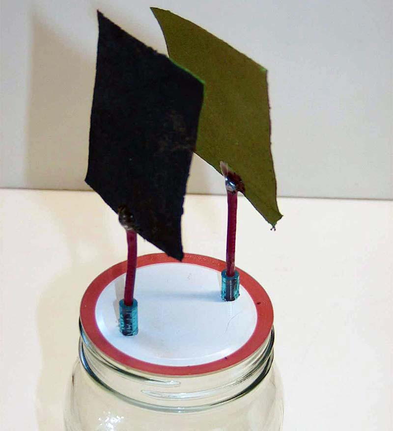
FIGURE 6B. Plates outside the cell.
Your cell is now ready for charging!
Note: Commercial cells also use lithium hydroxide (15g/l) in the electrolyte which further protects the cell at higher voltage charging.
Charging
Each of your Edison cells will produce 1.2 volts. Edison himself recommended charging these cells initially at 1.7 volts (for 48 hours) as a forming charge, and that daily chargings should be made at 1.45 volts to reduce gassing. Your cell will improve each time you charge/discharge it. He also recommended only discharging your cell to .9 volts while your plates are still forming.
Your cells will take on a charge very slowly, especially at first. Limiting current to 50 milliamps or less is recommended for the first charge, though Edison said larger currents are fine as long as the electrolyte does not “froth” or exceed 115 degrees. Some gassing at the terminals is normal and harmless. If liquid levels begin to get low in the cell, add distilled water only.
After your cell has checked out and is working exactly as you’d like, you can add 2 mm of mineral oil to the top of the cell. This will form a barrier against carbon dioxide, which can harm the cell over long periods of time.
A Unique Project
In trying to think of a fun and useful way to test such a long lived cell, I struck upon the idea of a “20 year garden light” as a project.
It occurred to me that using these homemade cells in place of the usual NiCad or NiMH batteries in a solar powered garden light (which usually only last a couple years at best), I might wind up with a light whose battery outlived its solar panel and other components. A quick test showed that two of the described hobby cells could power a low power LED overnight, so I set up a simple solar night light that has been working for about a year now.
Figure 7 shows a typical “on after dark” circuit. The resistor at the transistor’s collector should be calculated based on your LEDs operating volatage and the number of cells you choose to use in the circuit. The 50K pot will determine the circuit’s sensitivity to sunlight.
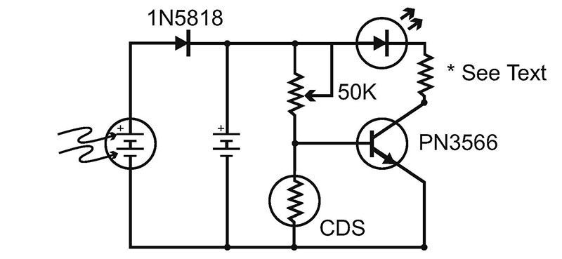
FIGURE 7.
Final Thoughts
Though the homebrewed cell outlined here has a very limited capacity, I hope you’ll find its fundamentals as truly fascinating as I have.
I believe all the principles necessary are here for creating larger cells and following in Edison’s considerable footsteps in other designs.
Surprisingly, my first introduction to Edison cells was at a local energy fair more than 20 years ago. A professor from a junior college exhibited a Volkswagon converted to run on a large set of antique Edison cells. The cells in his car — many more than 50 years old — had been operating his Volkswagen with off-the-shelf motor and other components throughout the school year. He claimed a range of nearly 100 miles, and a top speed of 60 MPH … besting many of the new breed of electric cars today!
New batteries may well soon eclipse what has been done in the past, but sometimes older technology can surprise you! NV
I’d like to thank Ellsworth Adhesives for donating the conductive epoxy, and Dr. Vijayamohanan K. Pillai for his encouragement and advice in sorting out the fact and fiction on these remarkable cells.
SOURCES
A good source for pottery oxides/pigments:
www.uspigment.com/
For industrial quality conductive epoxy:
www.ellsworth.com/
For electrolyte chemicals (and often oxides as well):
www.ebay.com/
For top (laboratory) quality chemicals, I'd recommend suppliers like United Nuclear, Spectrum, and always a Google search!