Not long ago in an electronics forum on the Web, a question popped up on how to build a certain complex device. Besides several helpful responses, there was one that struck me as missing the point altogether. In particular, the respondent said something like, "Why build it when you can buy a commercial one?" Of course, in some circumstances our time is worth more than the cost of a purchase. However, if our goals include learning something new as we go along, taking pride in what we've built with our own hands, or even saving a little money at the expense of time, then there's still much satisfaction to be found in our craft. Apparently, I'm not the only one who feels this way because the respondent took some heat.
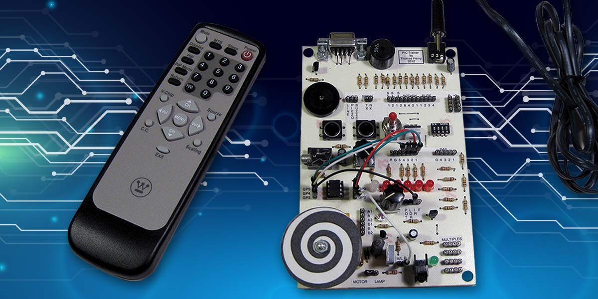
If you too relish the feeling of accomplishment in building a personalized and/or customized project, then have I got a deal for you! This article demonstrates how to assemble a versatile PIC trainer using only surplus parts. Belying its humble origin, this really is an open-ended and high quality learning tool. In the brief time I’ve been using it for my own education, I’ve already written code for and whipped together a number of fascinating circuits. Thanks to the breadboard-like nature of the trainer, it’s a snap to go from a theoretical concept to a working project in a matter of minutes. Plus, the circuit has been carefully designed to be virtually indestructible, making it suitable for even the most careless of learners.
Sure, you may be able to find commercial units that’ll do the trick, but by building your own from scratch you’ll be enhancing the learning experience while simultaneously arriving at a tool you can put your own personal stamp on. Best of all, this PIC trainer is easily customized to your own purposes, and by taking advantage of what’s currently in your junk box it will hardly dent your wallet.
A Tour of the Trainer
So, what can you do with it? Figure 1 gives an overview of the components that make it up. Fitting on a single 4” by 6” circuit board, applications can be broken down into six categories:
- Visual indicators
- Switches
- Analog and audio output
- Analog input
- Higher power devices
- Serial input and output
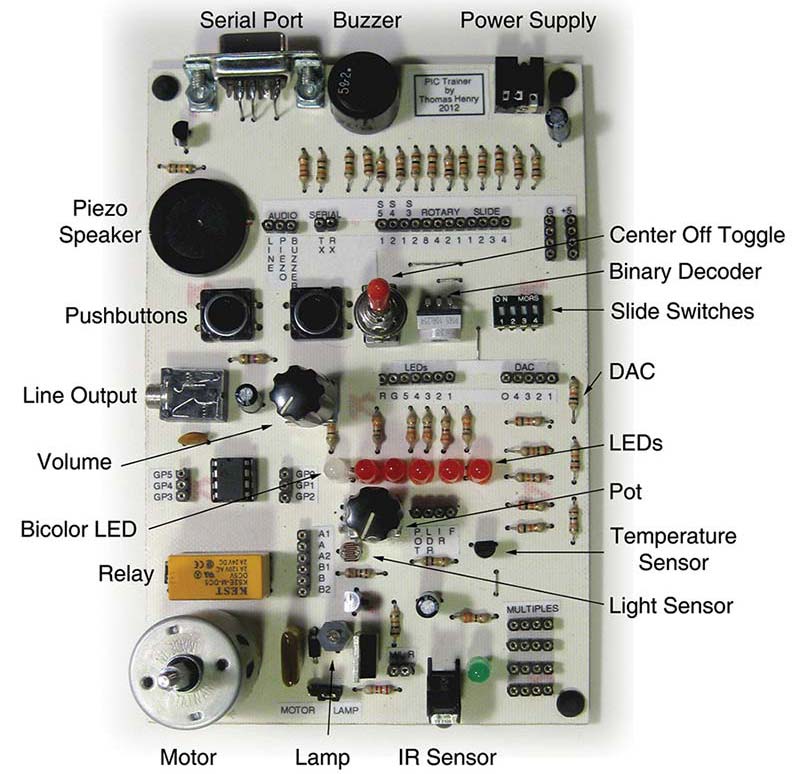
FIGURE 1.
Let’s take a brief tour of what’s available on the PIC trainer. The unit is configured around the inexpensive and easy-to-use PIC12F683 microcontroller. This is an eight-pin device, with a maximum of five outputs available at any given time. For visual displays, there are five red LEDs. Additionally, there is a single bicolor LED which can show red or green, or even orange if you alternate the signal applied to it. Lastly, I also threw in an ordinary incandescent lamp just to demonstrate how easy it is to control higher current devices.
You’ve got a lot of options for switches, starting with a pair of momentary pushbuttons. There are also four slide switches for set-and-forget operations. Next is a center-off SPDT toggle switch. This is great for demonstrating how software can sense three states using only two port pins. Last is the fascinating four-bit rotary switch. This neat apparatus spits out binary numbers from zero to 15.
There are three main options for audio output. First off is an electromechanical buzzer for alarm applications. The piezo speaker can be used to create more musical effects. If the piezo isn’t loud enough to suit you, then there’s a line output jack with associated volume control. This can feed an external amplifier if desired. The circuit is designed so it can also safely drive an outboard loudspeaker directly.
A four-bit digital-to-analog converter (DAC) is available for experimentation, as well. I put this in primarily for demonstrations on an oscilloscope. If you’re driving something with a lesser impedance, then you’ll want to buffer the signal.
Our trainer is no slouch when it comes to analog input, either. Remember that the PIC12F683 has built-in analog-to-digital conversion (ADC) facilities so it’s easy to read the included temperature and light sensors, as well as the uncommitted potentiometer. The really neat thing is the infrared (IR) sensor. This responds to the codes emitted by an ordinary television remote control.
It is often the case that a microcontroller is expected to tame higher power devices. For ventures along these lines, I’ve included a DPDT relay and a DC motor. With regard to the latter, the ever versatile PIC12F683 also includes pulse width modulation (PWM) capabilities, so it’s a snap to efficiently control motor speed this way.
Finally, for communicating with PCs and other external devices, there is a standard DB-9 type connector for sending and receiving data by means of the RS-232 protocol. If your computer has a serial COM port, then you can connect it up directly. Otherwise, you’ll need to attach one of those cheap USB-to-COM connectors.
Interconnecting the various subcircuits is fast and easy, thanks to the SIP sockets. These provide openings much like those found on a solderless breadboard. You’ll be able to patch together whatever you want in a matter of seconds. I got a handful of snazzy color-coded flexible jumpers from Amazon.
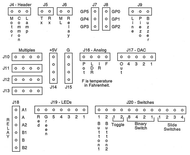
FIGURE 2.
Figure 2 shows the socket arrangements. There are even a few extras thrown in for use as multiples and, of course, the +5V and ground lines are available, as well. By the way, the motor and lamp share the high power Darlington transistor, so there is a male header (J4) which lets you choose which one you want.
Simply slip one of those little jumper clips over two adjacent pins to make your selection. To keep everything straight, I printed out labels and affixed them to the printed circuit board (PCB).
As you can see, there’s a lot going on within our PIC trainer. In fact, it seems so fancy that I should probably remind you once again that the whole shebang (apart from the inexpensive PIC12F683) is built with surplus parts. Just don’t let the discounted nature of the trainer deceive you. It’s possible to do some serious work with this high quality beast.
First Step: Understand It
Let’s turn our attention to how the PIC trainer works by wending our way through the schematic in Figure 3. You’ll want to socket the PIC12F683, of course, as well as make provisions for connection to its pins.
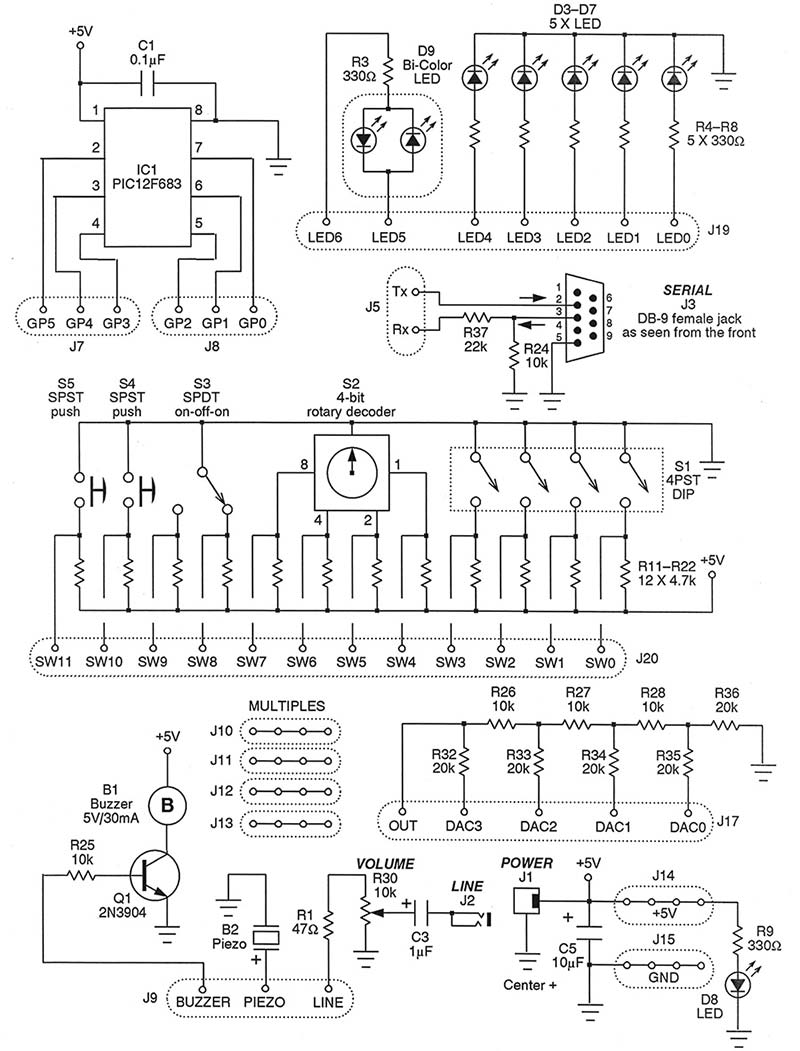
FIGURE 3.
Notice that all six of the I/O port lines are brought out to sockets J7 and J8.
The LEDs have the typical current-reducing resistors in place, R3 through R8. The red ones simply connect to ground, while the bicolor LED makes both legs available.
Turning to the serial port, J3, you’ll notice the series protection resistor, R37. This is needed since RS-232 signals can swing as much as 12 volts — positive or negative. R24, on the other hand, is simply a pull-down to keep the sensitive input line from floating.
As for the switches, each has a pull-up resistor, R11 through R22. These ensure that the PIC isn’t looking at input lines bobbing about in an indeterminate state. There’s a lot of repetition here, but really it’s nothing more than 12 switch elements and 12 pull-ups.
Let’s check out the audio stuff next. Keep in mind that a typical port line on a PIC can source or sink no more than 10 mA. For that reason, the electromechanical buzzer is buffered by transistor Q1. The piezo is a low current device, however, so it can connect to the PIC directly.
The line output features a 10K volume control and blocking capacitor C3. Easy to miss is series resistor R1. With this in place, it is safe to connect an ordinary 8Ω loudspeaker. The line output may also go to an external amplifier if desired.
The DAC is the trusty old R-2R affair, so called due to the values of the resistors employed. Remember, it’s not buffered so don’t expect to drive any low impedance circuitry directly without some additional components.
Finally, power is supplied via a regulated +5V wall wart. J14 and J15 make the supply voltage available for outboard components.
Now, turn to Figure 4 for the remaining circuitry. At the top, you’ll find the analog sensors. Temperature chip LM34DZ is a no-brainer; just hook it up directly and away you go! The output is already scaled to Fahrenheit, so the source code required for the microcontroller is very short and sweet.
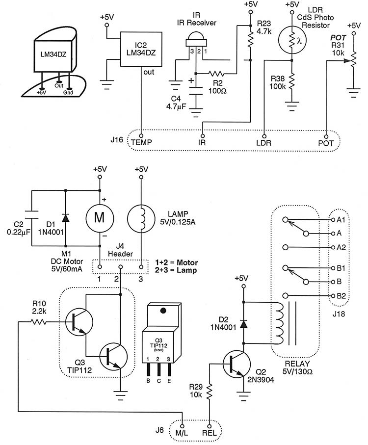
FIGURE 4.
The light sensor is a cadmium sulphide photoresistor, or light dependent resistor (LDR). This is tied in series with R38 to create a voltage divider. The uncommitted potentiometer, R31, is also a voltage divider. Recalling that the PIC12F683 contains ADC circuitry, then it’s equally easy to take a light reading or peg the position of the pot.
As for the IR sensor, be sure to double-check the pinout for whatever unit you’re using. In my case, pin 2 is hot while pin 3 is ground. Notice R2 and C4 which filter the supply voltage somewhat. The output is pulled up by resistor R23 and is finally made available to socket J16.
The relay is a fairly high powered device, so it’s controlled by means of transistor Q2. Rectifier D2 snubs any reverse-EMF, protecting both the transistor and the microcontroller.
The motor and lamp are also higher powered devices. In this case, we’ll use the even beefier Darlington transistor, Q3. The male header, J4, lets you choose whether the transistor controls the motor or the lamp.
Second Step: Collect the Parts
Many of the components in this circuit are commonplace; things like capacitors, resistors, and the like. You probably already have the bulk of them in your junk box but some of the more unusual items might give you pause. I had no trouble outfitting my trainer using surplus parts. In fact, one shopping trip did the trick. I basically got everything I needed for the entire project from All Electronics. Here are a few comments on several of the parts.
The PIC trainer is powered by a regulated +5V wall wart. The one I stumbled on, however, had a weird connector so I clipped it off and replaced it with a standard 2.5 mm barrel type. This mates with PCB-mounted receptacle J1. A green LED, D8, indicates power-on status.
The IR sensor in the trainer expects to read a signal from a Sony type remote control unit. I found just such a hand controller at All Electronics for two bucks, and it works very well. Alternatively, you could use one of those universal remotes, as long as it puts out the Sony codes.
Now about the sensor. It’s the nature of the surplus business for stock to change without warning. I designed this circuit around a Vishay TSOP2138 IR sensor I purchased earlier. However, I’m now seeing one manufactured by Sharp that is probably a decent substitute. It’s possible the pinout is different, so be sure to check the datasheet before building with it.
Just so you know, most of these inexpensive IR sensors use a standard 38 kHz carrier frequency, so even if the pinout changes the firmware will remain much the same.
The sockets (J5 through J20) actually all come from the same source: a snappable SIP affair. Essentially, this is one long row of sockets that you simply snap off a portion of to create the desired size. A pair of needle-nose pliers helps make a clean break. The PIC12F683 is a common microcontroller costing no more than a few bucks, so why not pick up a couple while you’re at it.
Third Step: Build It
There is absolutely nothing critical about the trainer circuitry, so feel free to build it on perfboard by hand if desired. I prefer PCBs myself, and it was simple enough to work up the pattern. I transferred it to a copperclad board with nothing more than a small travel iron (for pressing clothing). The etching was done in a Tupperware tank right in the kitchen. It’s a simple homely affair, but in less than a half hour I churned out a decent board. The drilling took place in the workshop, of course, using a Dremel drill press. Don’t forget to slip on a pair of goggles before starting.
Since we’re using surplus parts, you might find (like I did) that occasionally you’ll have to clip an extraneous tab off of a component or drill out a bigger hole to accommodate it on the PCB. It’s not a big deal — essentially you’re customizing as you go along. Figure 5 shows the parts placement guide for my rendition.
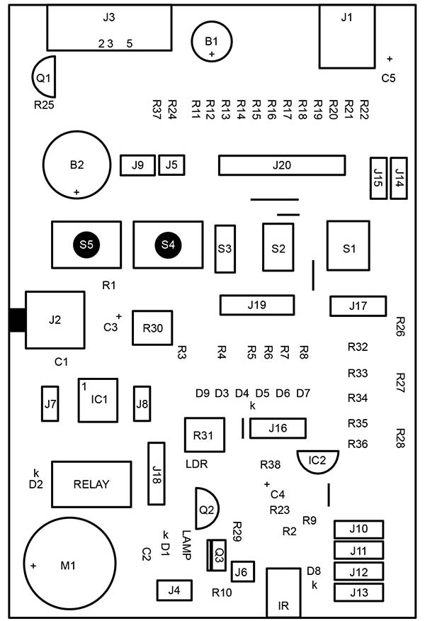
FIGURE 5.
Final Step: Use It!
Now comes the fun part — actually putting it in motion. Remember, this is a trainer so you’re supposed to be learning something. The thing is so much darn fun to use, though, that the education comes along gratis.
I’ve provided some sample projects (written in the free open source Great Cow Basic language which is perfect for beginners) to get you started. You’ll find the source code below in the downloads. Just as a teaser, you’ll see how to:
- Log temperatures minute by minute and send them to a PC.
- Control motor speed with the television remote.
- Play a bit of music.
- Do some blinky LED things, of course.
If you really want to learn about microcontrollers, then jump in and try your hand at a custom circuit. The sky’s the limit with your very own PIC trainer built from surplus. NV
PARTS LIST
| ITEM |
DESCRIPTION |
| All fixed resistors are 1/4 watt, 5% values. |
| R1 |
47Ω |
| R2 |
100Ω |
| R3-R9 |
330Ω |
| R10 |
2.2K |
| R11-R23 |
4.7K |
| R24-R29 |
10K |
| R30, R31 |
10K potentiometer |
| R32-R36 |
20K |
| R37 |
22K |
| R38 |
100K |
| All fixed Capacitors are 1/4 watt, 5% values. |
| C1 |
0.1 µF disc |
| C2 |
0.22 µF mylar |
| C3 |
1 µF electrolytic |
| C4 |
4.7 µF electrolytic |
| C5 |
10 µF electrolytic |
| Semiconductors |
| D1, D2 |
1N4001 rectifier |
| D3-D7 |
Red LED |
| D8 |
Green LED |
| D9 |
Bicolor LED (LED-6) |
| Q1, Q2 |
2N3904 transistor |
| Q3 |
TIP112 Darlington pair |
| IC1 |
PIC12F683 microcontroller |
| IC2 |
Temperature sensor (LM34DZ) |
| Switches |
| S1 |
4PST DIP switch (DWS-4S) |
| S2 |
Four-bit binary switch |
| S3 |
SPDT center-off toggle (MTS-5) |
| S4, S5 |
SPST pushbutton |
| RELAY |
5V/130W DPDT relay (RLY-625) |
| Jacks and Sockets |
| J1 |
2.5 mm DC jack (DCJ-17) |
| J2 |
3.5 mm stereo audio jack |
| J3 |
Female D-9 jack (DB-9S) |
| J4 |
Three-pin male header |
| J5, J6 |
Two-pin SIP socket |
| J7-J9 |
Three-pin SIP socket |
| J10-J16 |
Four-pin SIP socket |
| J17 |
Five-pin SIP socket |
| J18 |
Six-pin SIP socket |
| J19 |
Seven-pin SIP socket |
| J20 |
12-pin SIP socket (See text for information on SIP sockets.) |
| Other Components |
| B1 |
5V/30 mA buzzer |
| B2 |
Piezo speaker (PE-54) |
| IR |
Infrared receiver (see text) |
| LAMP |
5V/125mA lamp (LP-715) |
| LDR |
CdS LDR (PRE-24) |
| M1 |
5V/60 mA DC motor |
| Miscellaneous: +5V regulated wall wart (PS-513), power plug (DCLID), TV remote control, circuit board, IC socket, solder, wire, rubber feet, etc. |
Downloads
What’s in the zip?
Source Code
PCB Layout