I’m going to describe how to construct your very own two-bit non-volatile memory using a seemingly magical material. I hope that you find this subject so fascinating that you demand more information ...
Introduction to Magic
Magic, of course, is technology we don't understand. Once understood, it ceases to be magic; it becomes a cell phone or a computer or an MRI scanner. A peek inside any of these machines always puts me in a state of awe.
They all run on a magic crystal which has been purified beyond belief, and formed into a single lattice so perfect that it makes a jewel-quality diamond look like a dirty window. As potters have done for thousands of years, we paint minerals on this crystal, fire it in the space-age versions of kilns, and cover it in a glaze to protect its innards from the poisons in our sweat. This magic crystal is silicon.
Using Einstein's entreaty that geometry is everything and calculating the required dimensions using the quantum physics that Einstein helped create but never believed, we package up tiny silicon crystals of amazing variety and configurations, connect them together, and perform feats today that would have been considered magic in 1954 (when I was born). Imagine my disbelief a decade ago when I called home to New Mexico from a car on a highway in Korea. This magic is now the everyday mundane.
Fear not, more magic is on the way! Lots more!
Physics is the fundamental basis of all science. (Just ask any physicist! He or she will gleefully assure you of this perceived truth.) However, physics has different disciplines. The one in which we are interested is solid state physics: the study of materials. From this discipline springs our knowledge of silicon and how to bend it to our will. Solid state physicists — who date to a time long before the Lycurgus Cup of 400 A.D. (look it up!) — know thousands of materials with electrical or mechanical properties that appear at first to be magical. In this article, I will introduce you to just one: lead zirconate titanate, or PZT.
While silicon circuits think logically, PZT feels, detects, moves, and remembers. Connecting PZT devices to silicon circuits is like connecting a body to a brain. PZT and a whole host of related materials called ferroelectrics are poised to greatly expand the usefulness of silicon circuits — even to the point of allowing them to move of their own volition.
Radiant Technologies has quietly worked on this technology since 1988 to make it useful not just for large manufacturers, but to the individual as well. We now manufacture discrete versions of ferroelectric devices that you can insert into circuits for experimentation. The concept of using highly non-linear materials in such a manner is so new that there are hardly any examples of useful circuits. The power of these materials is mesmerizing, and it is my hope that you will experiment with them and kick out new ideas along the way.
The first discrete ferroelectric devices I will discuss are capacitors, but they are to traditional capacitors as transistors are to diodes. You have a lot to learn and there are no text books! Therefore, we will start with the simplest of applications: non-volatile memory.
The project discussed here creates a discrete two-bit ferroelectric memory that operates in the same manner as the Ferroelectric RAM (FRAM) embedded in products now made by Texas Instruments, Cypress, Fujitsu, and Rohm. First, I will explain the fundamental properties of ferroelectric capacitors, i.e., where does the memory come from? I will then show how to connect them to a microprocessor to store and read non-volatile data.
This project should challenge the very way you think about electronic components. Where a diode or a capacitor or a transistor is a cold-hearted mechanistic object that never varies from the equations physicists say it should follow, a ferroelectric capacitor is born with memory and always has memory. A ferroelectric capacitor is never empty. The circuit here simply orients that ferroelectric memory and later asks the capacitor to tell us what it knows. Let's get started!
Ferroelectric Theory
Unlike EEPROM or flash solid state memories that shoot electrons into insulators, the crystal lattice of a ferroelectric capacitor is naturally polarized. Each unit cell of the lattice is a small electric dipole that points towards one or the other electrode.
A dipole is defined as the spatial separation of "+" and "-" electrical charges. Dipoles come into being in traditional capacitors when a voltage is applied, but they go away again at zero volts. In ferroelectrics, the dipoles are always present. The unit cell is about 4 Ångstroms on a side, so even a ferroelectric capacitor only one micrometer on a side (one hundredth the width of a human hair) has billions of internal natural dipoles within its volume. Each dipole can be rotated by an external voltage causing distortion in the lattice that remains when voltage is removed.
Think of the lattice distortion as an over-center lock that holds all of the dipoles pointing in the forced direction. A ferroelectric capacitor need only have all of its dipoles point in the same direction to form a detectable memory state in that capacitor. Applying the opposite voltage to the capacitor switches the dipoles to the opposite direction. The alignment of the dipoles in a single direction results in a net electric field inside the capacitor.
That field attracts and holds extra charges onto the capacitor plates to prevent any dipole-generated electric field from escaping the capacitor volume. It is from the movement of that extra charge to/from the plates as the dipoles change direction that we can determine the memory state of the capacitor.
Many readers will remember building a crystal radio that used a quartz crystal to detect and de-modulate an AM radio signal. The quartz crystal could accomplish this magical feat because it too has a charged lattice like a ferroelectric crystal. The difference between the two is that the ferroelectric material allows its internal dipoles to be rotated in different directions while quartz does not. This property of quartz makes it an electret material, as opposed to a ferroelectric material like PZT.
Non-volatile memory using ferroelectricity is charge based, not voltage based. Its state is destructively read by counting electrons coming from the capacitor when it is forced into a known direction. The value of the state (1 or 0) is related to how many electrons come out. Did the capacitor switch the dipole direction or not? The material itself is not damaged by these operations nor is its ability to be re-written affected.
The charge coming from a ferroelectric capacitor is most easily converted to a voltage for detection by a linear capacitor in series with the ferroelectric capacitor. This arrangement is known as the Sawyer-Tower circuit. A non-volatile ferroelectric memory bit may be created by connecting a Sawyer-Tower circuit to two I/O pins of a microprocessor to take advantage of the unique property of microprocessor pins, whereby they can act as active outputs or as high impedance level-sensing inputs. Microprocessors with comparator or ADC (analog-to-digital converter) pins will allow even more robust operation of the Sawyer-Tower circuit.
The circuit in Figure 1 shows a Sawyer-Tower circuit connected to two I/O pins of a microprocessor. The plot in Figure 1 shows two single-cycle hysteresis loops of the ferroelectric capacitor starting from opposite dipole orientations.
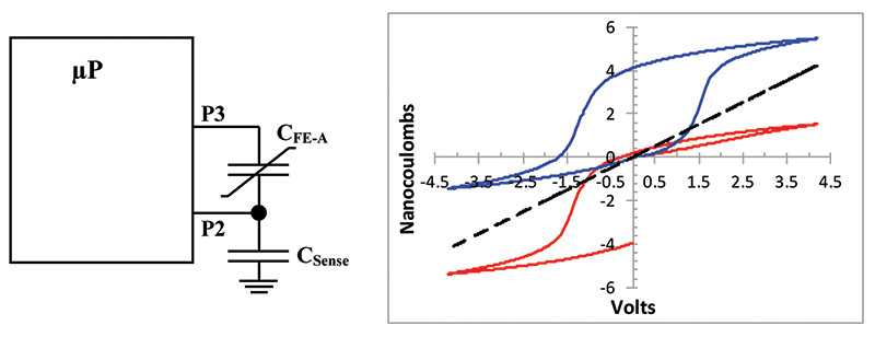
FIGURE 1. Single-bit non-volatile ferroelectric memory attached to a microprocessor and the associated UP/DOWN ferroelectric hysteresis loops.
Note that all hysteresis plots shown in this article are measurements of actual devices. They are not hand drawn loops or simulations. The horizontal axis is the voltage applied across the ferroelectric capacitor. The vertical axis is the count of the charge that comes from the capacitor during actuation.
All measurements start with the Sawyer-Tower sense capacitor initialized to zero volts, so the memory state of the capacitor determines vertical positioning on the Y axis. If the dipole direction does not switch, only a small amount of charge comes out, and it goes almost back to zero like a standard capacitor when the voltage recedes. If the dipoles do switch, a lot of charge comes out with the positive voltage, but not all of that charge can go back in when the voltage returns to zero. In order for all of the switched charge to go back in, the dipoles must switch back on their own, but they don't! Since the ferroelectric capacitor ends up with all dipoles pointing positive after the application of the positive voltage independent of the capacitor's original state, full dipole switching always takes place during the negative voltage application portion of either loop.
As a reference, there is a third loop in the plot of Figure 1. The straight gray line is the hysteresis loop of a very linear 1 nF capacitor. The formula for a capacitor is Q=CV. For a linear capacitor, the capacitance term in the formula is constant, so this becomes the formula for a line centered on the origin with slope equal to the capacitance. The comparison of the linear capacitor hysteresis with the ferroelectric hysteresis clearly highlights the magic of a ferroelectric capacitor. The plot also gives the perception of the total charge that comies out of this particular ferroelectric capacitor. Some would argue that a linear capacitor does not have hysteresis. I maintain that zero is a number, so a linear capacitor has a hysteresis loop!
From the diagram, it can be seen that if the ferroelectric capacitor has all of its internal dipoles oriented DOWN prior to the positive half of the loop, switching occurs in a single pass. However, if the remanent polarization is pointed UP before the loop begins, only a very small non-switching loop occurs in the first half of the cycle.
The difference between the two half loops in the positive quadrant of the plot is the difference in voltage that will develop across the sense capacitor of the Sawyer-Tower loop during a read operation. The value of the sense capacitor of the Sawyer-Tower circuit should be selected so that the UP memory state will not generate enough voltage across P2 to be read as a high logic state, but the DOWN memory state will. Once the read operation wipes out the stored datum, it must be re-written afterwards.
The four parts of Figure 2 show the Write UP, Read UP, Write DOWN, and Read DOWN operations and their associated pin assignments.
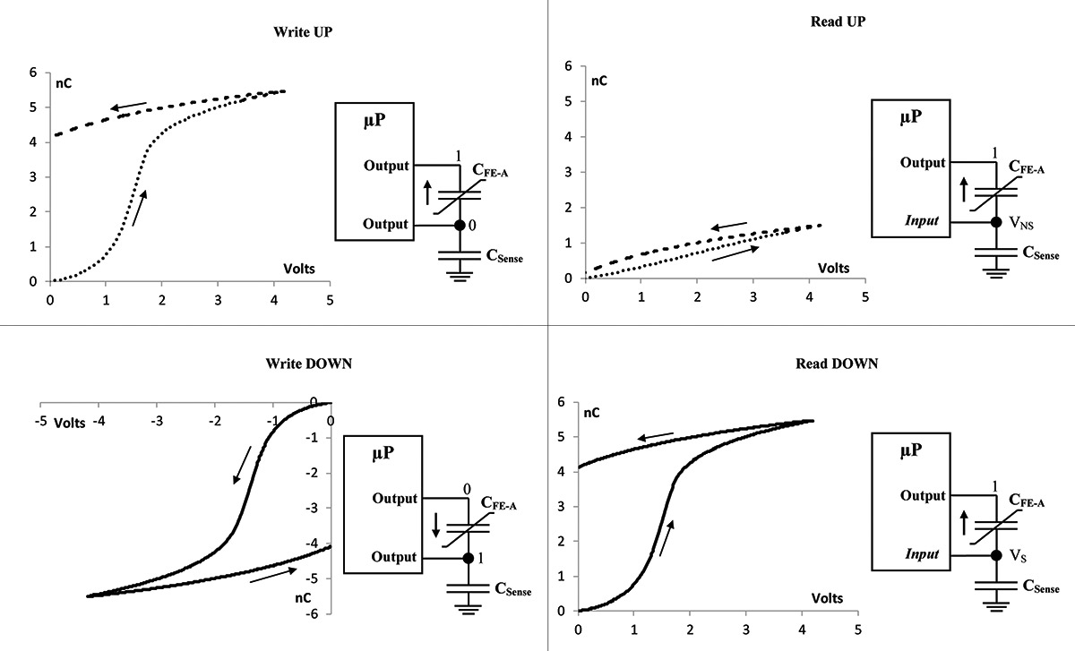
FIGURE 2. Write and read operations, and the associated signals on P2.
Figure 3 combines the Read UP and Read DOWN results into a single plot. Csense should be sized so that the UP signal is less than the logic 0 threshold for the microprocessor input, while the DOWN signal must be greater than the logic 1 threshold.
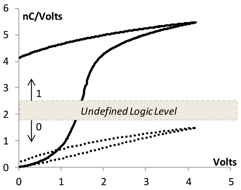
FIGURE 3. Comparison of UP and DOWN memory states during the read operation.
Discrete Ferroelectric Capacitor
Radiant Technologies manufactures several types of discrete capacitors, and then packages matched pairs in old-style TO-18 four-lead transistor packages (refer to Figure 4).
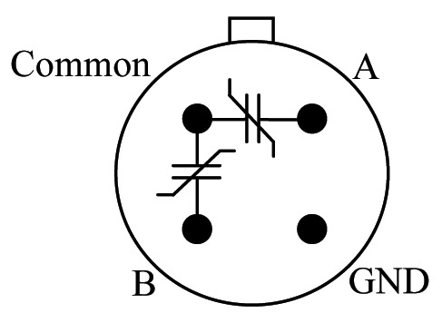
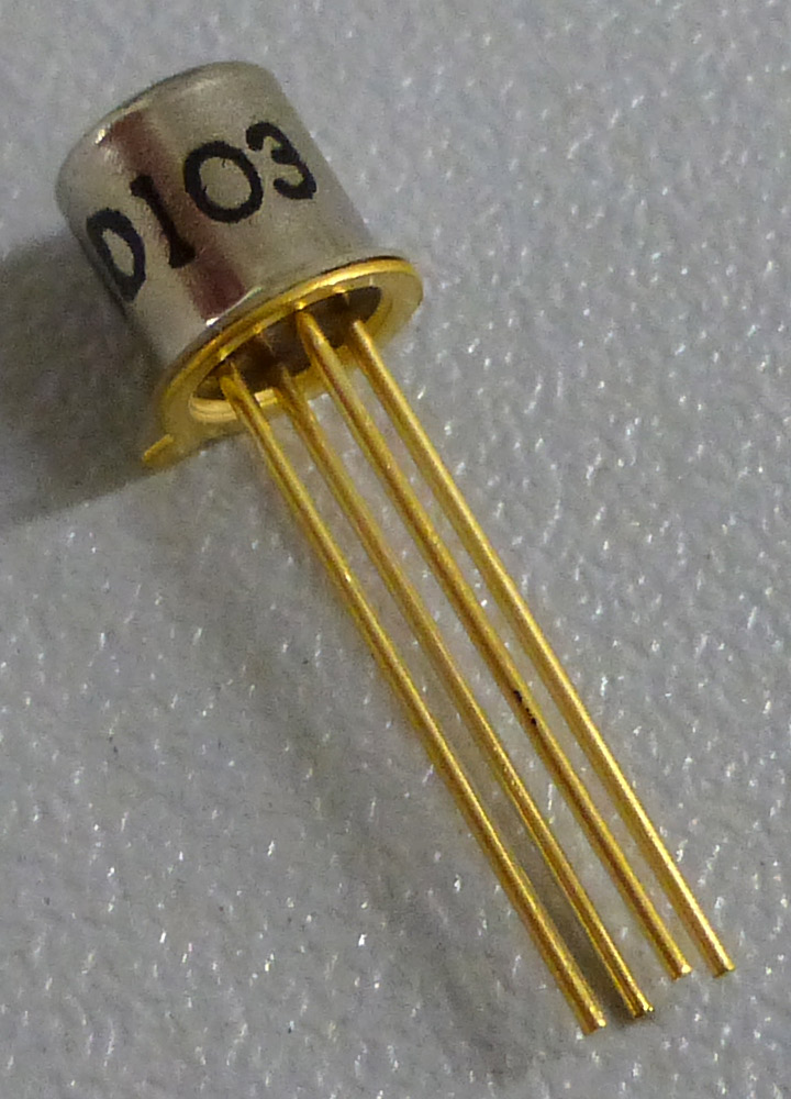
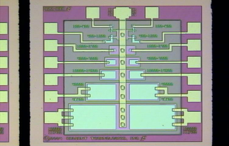
FIGURE 4. TO-18 package, top-view pin assignments, and a photograph of the die.
The capacitor that should be used with microprocessors is the Type AD, which saturates above 2.2 volts and can operate at 4.2 volts for about a year at 85°C.
The capacitor used in this article has 10,000 square microns of area (Type AD103), making it 2,500 to 40,000 times larger than the ferroelectric capacitors used in the FRAM memory arrays in TI, Fujitsu, Cypress, and Rohm products.
Capacitor properties do not change with a larger area, but the amount of charge produced by the capacitor tracks linearly with the area.
If the ferroelectric capacitor doubles in area, then the Sawyer-Tower sense capacitor must increase its capacitance proportionately in order to maintain the same sense voltages.
For detailed information on how to select the sense capacitor and mathematically determine circuit performance, go to www.ferromems.com and click on the link for "Theory - Ferroelectric Memory."
The AD103 capacitor works most easily in logic mode with a 1 nF to 2 nF sense capacitor.
Microprocessors
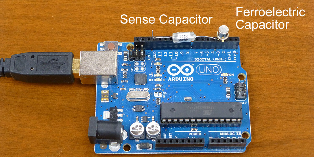
The Arduino Uno microprocessor (Arduino.cc) shown in Figure 5 with the Sawyer-Tower memory circuit can be configured to work with the Type AD ferroelectric capacitor to form an external non-volatile memory bit.
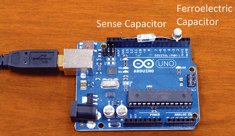
FIGURE 5. Arduino Uno with Sawyer-Tower circuit.
The BASIC Stamp® microprocessor by Parallax (www.parallax.com) in Figure 6 is also an excellent choice.
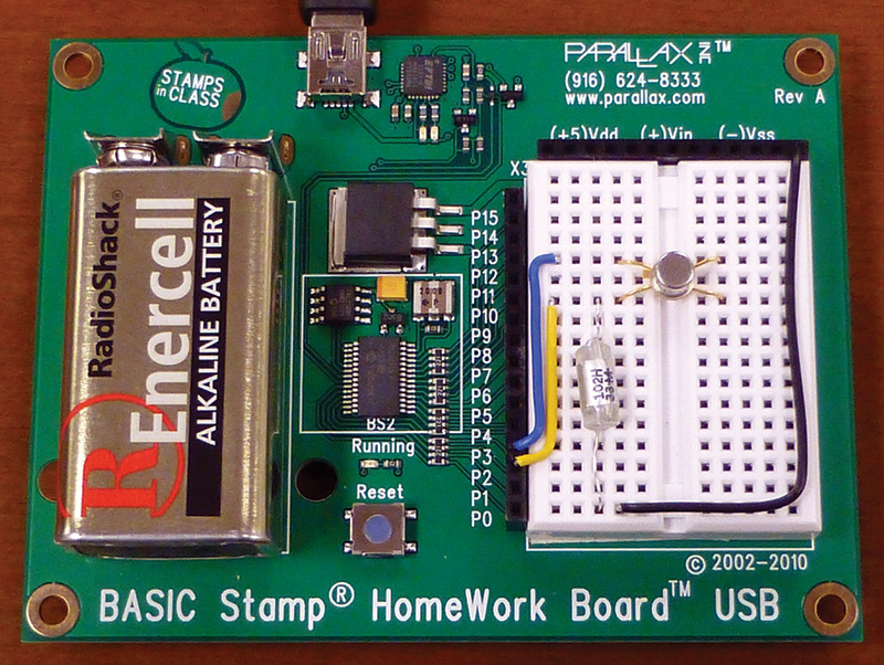
FIGURE 6. BASIC Stamp with P3/P2 connected to a Sawyer-Tower circuit.
Both are available from a variety of sources, are inexpensive, have five volt I/O pins, and are easy to program from any PC by USB connection.
Ferroelectric capacitors made with PZT are extremely fast. The Type AD capacitors can be written to either state in less than 100 nanoseconds.
Thus, the most difficult problem associated with using them in non-volatile memory is to prevent stray voltages from being applied inadvertently. The slightest blip you cannot even detect can fully switch a capacitor that should not be switched. This is especially true during power changes.
You cannot use a microprocessor that does not default all I/O pins to input mode during power-up. At the same time, the I/O pins connected to the Sawyer-Tower circuit must be set as inputs prior to turning off power. It is good practice to set these pins as inputs whenever the ferroelectric capacitor is not being accessed.
When the pins are to be activated as outputs, they should first be set to zero volts out before being changed from input to output. They should both return to zero volts after a read or write operation before changing them back to input mode.
Thus, every operation involves the following order of steps:
- Write "0" to both pins while they are set as inputs.
- Change pins to outputs.
- Execute the read or write operation.
- Return to "0" on both pins as the last step of any operation.
- Change both pins to inputs.
Table 1 uses the pin definitions shown in Figure 1.
| Operation |
Instruction |
P3 |
P2 |
| Write UP |
| |
1 |
0 |
0 |
| |
2 |
1 |
0 |
| |
3 |
0 |
0 |
| Write DOWN |
| |
1 |
0 |
0 |
| |
2 |
0 |
1 |
| |
3 |
0 |
0 |
| Read |
| |
1 |
0 |
Input |
| |
2 |
1 |
Input |
| |
3 |
1 |
Read |
| |
4 |
0 |
0 |
| |
5 |
Re-write |
|
TABLE 1. Generic I/O commands to operate a simple ferroelectric memory.
Note that the P3/P2 pin assignments in Table 1 match the circuit layout on the BASIC Stamp in Figure 6. The pin assignments are reversed on the Arduino in Figure 5.
Figure 7 shows an oscilloscope image for the P3 and P2 signals for the write/read operations of the two logic states on the Stamp. Sample code files for both microprocessor types can be found in the downloads link, at the end.
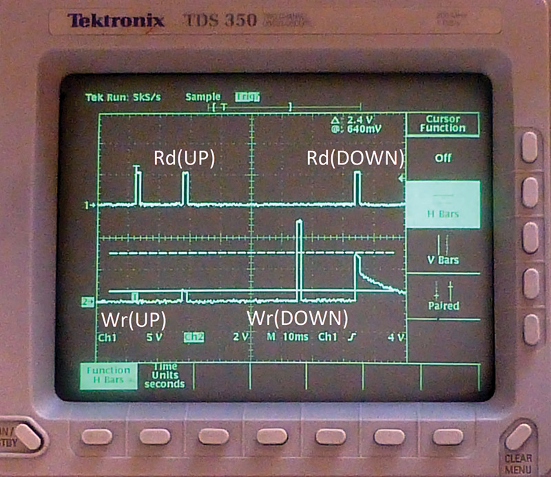
FIGURE 7. Oscilloscope trace of P3 and P2 for a Write/Read UP/DOWN sequence.
Read operations are destructive just like in DRAM operations. The FRAM memory read procedure always leaves the UP condition after the operation is completed. If a DOWN state was previously stored in the bit, it should be re-written after the read operation is completed.
Note that speed is not a consideration in programming the write and read pulses. PZT capacitors physically switch faster than the command execution speed of either processor. The only speed limitation arises if the ferroelectric capacitor is so large that it loads the current delivery capacity of the I/O pin. For example, suppose the I/O pin can deliver 20 milliamps which is defined as 20 millicoulombs per second.
Figure 3 shows that the 10,000 square micron AD103 capacitor requires slightly less than six nanocoulombs to saturate. A little arithmetic indicates that a 20 mA I/O pin should be able to saturate the AD103 in approximately 300 nanoseconds! Neither the Stamp nor the Arduino can execute a digital pulse on an I/O pin that fast.
Two Bits Instead of One
The Type AD capacitor package contains two identical capacitors. By connecting the second capacitor to its own I/O pin, a two-bit non-volatile memory is created (refer to Figure 8).
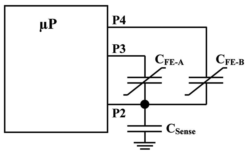
FIGURE 8. Two-bit ferroelectric non-volatile memory.
The same subroutines as above are used to access either capacitor in the package using P3 or P4 to select the capacitor address. P2 operation remains the same. If accessing P3, P4 must be set as an input to prevent voltage application across the P4 capacitor from the P2 node. If accessing P4, P3 must be set as an input.
Conclusion
Once the two-bit ferroelectric memory has been constructed, you can perform a variety of experiments or use the memory during operation of the microprocessor. For example, what four states do you want your garage door to remember?
Since the information is embedded in lattice distortions of the ferroelectric material, it is very robust. You can remove the two-bit package from the circuit after writing data, and carry it in your pocket without losing the written information. Plug it back in the next day to see if the data is still there.
The functionality of a discrete non-volatile memory using ferroelectric capacitors attached to a microprocessor is easy to understand. It is an excellent vehicle for developing a solid understanding of the memory properties of the ferroelectric capacitor.
This is necessary in order to move to the next step: a non-volatile latch using a ferroelectric capacitor that needs no microprocessor to execute reads and writes.
While a few bits of non-volatile memory operating from the I/Os of a microprocessor is not very exciting, an autonomous non-volatile latch is just the opposite! NV
Downloads
What’s In The Zip?
Data Plots, Basic Stamp source, Arduino Source.