Light a 100 Volt Bulb with the Waves that Surround You
With "smart" cell phones, Wi-Fi, RFID tag systems, and so many other new applications for radio waves these days, it is obvious that we are immersed in an electromagnetic field ("EMF") just about everywhere we go. Whether or not this is harmful to human beings is a controversial subject, although many scientists will tell you it is not hurting us at the present intensity level. However, you can easily demonstrate that such fields can be pretty strong. At the very least, this indicates an ever increasing need for shielding in hobby electronics projects, to avoid picking up troublesome noise.
Because there is so much EMF in the general environment, several research projects (mostly military) are purposely "harvesting" the energy and trying to use this to operate sensors, tiny transmitters, and other devices that will never require batteries or even solar cells. Another branch of the research aims to use strictly mechanical noise to harvest energy from the environment, similar to the way a self-winding mechanical wristwatch operates. However, many useful things such as sensors need electric power in some way, and it is usually inefficient to collect low-level mechanical energy and convert it to electricity.
Although a radio aerial converts electromagnetic waves into electricity, the voltages that are fed to cell phones from ferrite antennas are typically only a few microvolts. It might be a surprise to the reader, but a million times more voltage — possibly four volts or so — can actually be harvested by simple means from many common environments, by using a fairly long antenna and a good ground. The currents are small, but they can easily be accumulated, enough to briefly light a Tungsten incandescent bulb. With a transformer, these voltages can be stepped up enough to flash a neon bulb. It's amazing, but quite true, and all this can be verified with experiments that are easy to do.
The Experimental Set-up
The circuit is shown in Figure 1, but it is not necessary to use any actual switches. Alligator clips could be used instead. For example, looking at S1 in the diagram, a clip lead could be temporarily connected from the antenna to the AC voltmeter.
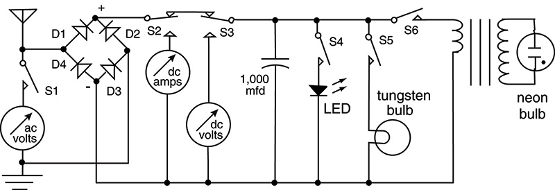
FIGURE 1.
For the antenna, a 15-foot-long extension cord can be used, or any other insulated wire of roughly that length. For the first experiments, it can be stretched out on the floor of your home, maybe extending into another room.
A "quiet" ground is needed, to avoid picking up stray voltages that are not electromagnetic in origin. It should be noted that the "return" or "neutral" wire of 120 volt AC power lines (color coded white in the US) is not suitable, because it often has considerable voltage on it, due to resistive ground connections. Using that would be cheating, if we are investigating the power that comes strictly from EMFs in the air. Similarly, the green coded safety connection might have about 10 volts on it — relative to true ground — if a clothes dryer or air conditioner is running nearby. For these experiments, a better ground connection can be obtained by hammering a bare metal curtain rod into the earth and attaching a clip lead to it.
The meter to measure the AC voltage can be any instrument with an input impedance of around 10 megohms, such as a portable digital multimeter. This could also be used to serve as the ammeter and DC voltmeter shown in Figure 1, if it is disconnected from position S1 and then reconnected at S2, and later at S3. Alternatively, of course, separate meters could be used.
A full wave diode bridge can rectify the input, as shown. However, good results can be obtained with just diode D1, with a plain wire in place of D3, and no connections at all in positions D2 and D4.
The LED should be a low current type, such as RadioShack catalog number 276-044, which will produce visible light with only two milliamps. The Tungsten incandescent bulb also has to be a low current type, such as RadioShack catalog number 272-1139 or similar, which will light up with only 20 mA. The transformer can be a step-down 120-volt to six-volt power supply type, which we will operate "backwards," in a 20:1 step-up mode. Switch S6 (or just an ordinary clip lead) is going to be used to dump the capacitor's charge into the low voltage winding, and almost any neon or argon lamp attached across the high voltage winding will then flash.
The Waves that Surround Us
Unless you are down in an iron mine, you are probably in a measurably strong electromagnetic field. Even inside a metal building, there is usually some oscillating field coming from the 120-volt AC power lines in the walls, just because of the power that always goes to computers, "instant-on" TV sets, and even the multiplicity of electric clocks that are in most people's houses. This is especially true in an urban or suburban area, if there are power lines up on telephone poles near the house — the amount of EMF radiation that they generate might surprise you. At any rate, you can sense such fields with the apparatus of Figure 1 and judge for yourself.
Inside a typical house or office building, quite a lot of our environmental EMF is 60 Hz AC or harmonics of it. Weaker radiation is at the extra-low frequencies generated by thunderstorms all throughout the world. A wide variety of radiation is being suggested as sources of energy to be harvested, as described in the publications that any Internet web search engine will turn up, if you enter "harvest electricity" in the dialog box. However, more and more RF will be at microwave frequencies, as we make increased use of things like the RFID tags that Wal-Mart and other big businesses are putting in place by the millions, and as Wi-Fi gets into more public places and home networks.
A Few Measurements
With a 15 foot or longer antenna snaking along the floor from room to room in a typical suburban house, and using a grounding rod outside, you are likely to see from two to four volts of AC (RMS). Surprisingly, this might not vary much as a high current appliance such when a clothes dryer is switched on and off. Taking the antenna outdoors, draped horizontally over some beach chairs over a backyard lawn, you can expect a lower voltage, possibly only a few hundred millivolts. Arranging the antenna vertically up a tree, the measured voltage is not usually much different, in spite of the fact that many radio transmissions are vertically polarized. Moving the whole apparatus to a front yard, near power lines on telephone poles, the measurements are likely to be more like what is seen inside a house, possibly a few volts. On the other hand, in a rural setting, away from houses and power lines, the voltages are likely to be lower.
Looking at the input with an oscilloscope attached in place of the AC voltmeter of Figure 1, there might be a lot of 60 Hz content visible in the received signal. In some cases, there is much distortion of the basic sine wave, and there is more harmonic content than fundamental, particularly at 120 Hz, due to various phase delays. There is almost always a great deal of continuously varying, high frequency hash riding on top of the steadily repeating signals. Some of this is at extremely high frequencies and consists of digital pulses, even though the simplified antenna biases the apparatus towards picking up low frequencies.
From observations such as these, it can be seen that our electronic devices need good shielding against EMFs these days. Maybe the shields will have to be improved in the future, as more and more of these invisible fields become commonplace. In many cases, it is already necessary to use "guards" as well as "shields," for devices such as op-amps with very high amplification factors. It also seems sensible to re-evaluate the possible effects on human beings from time to time, as these fields get more intense, and their frequencies go up.
Accumulating the Energy
With the attachment of a rectifier, DC can be stored in the 1,000 mF capacitor. The full wave diode bridge in the figure is efficient, but slower accumulation can be obtained with just D1, as mentioned above. By switching S2 (or just using a clip lead), the interrupted DC flow can be estimated, and typical readings inside a house might be (surprisingly!) as high as a few milliamperes, although a tenth of that is more common.
After approximately an hour of charging, the 1,000 µF capacitor voltage can be measured via S3. This will be the RMS AC voltage times the square root of 2, and four volts is typical when measured inside a suburban house. In an electrolytic capacitor, it is enough energy to light a low current LED, through S4. In fact, a brief flash can be visible in a low current Tungsten bulb, via S5.
Using S6 or the equivalent, the capacitor's charge can be suddenly dumped into the primary of a step-up transformer. (As mentioned above, a power transformer that is normally step-down can be used "backwards" for this experiment.) A ratio of 10:1 or 20:1 will usually light a small neon or other gas discharge bulb for an instant. On the oscilloscope, this pulse can register as high as 100 volts. Thus, a fairly high voltage can be harvested from our environment, by very simple means. NV
PARTS LIST
| Insulated wire |
15 or 20 feet long (for antenna) |
| Metal rod |
(for ground connection) |
| Diode |
Or full wave rectifier bridge |
| Capacitor |
1,000 µF or similar |
| Multimeter |
10 megohm input impedance |
| Clip leads |
Or 3 SPST and 3 SPDT switches |
| 2 mA LED |
Like RadioShack 276-044 |
| 25 mA bulb |
Like RadioShack 272-1139 |
| Transformer |
20:1 or similar |
| Misc. |
A small neon or argon bulb |