An uninterruptible power supply (UPS) ensures the continuous operation of critical electronic equipment. They are especially necessary if you live in an area where there are frequent power failures. They are manufactured to meet a wide range of power requirements, from backing up your personal computer to keeping your entire home office (or workshop) going during a power failure. Most UPS systems are designed to transparently maintain AC power to your equipment. They provide for a smooth transition from main power to backup power and back again.
There are a number of applications that have relatively low power requirements and run on DC rather than AC voltage but must also remain operational in the event of a main power failure. These include small security sensor modules, data acquisition, and status monitoring devices among others.
The block diagram in Figure 1 shows the organization of a simple DC UPS. It consists of an unregulated DC source, a backup power source, switching logic, and a voltage regulator. The voltage regulator supplies the application with regulated DC power. The input to the voltage regulator normally comes from the unregulated DC source. If the main power is interrupted, then the switching logic switches the backup power source to the input of the regulator. When main power is restored, the unregulated DC source is switched back into the circuit.
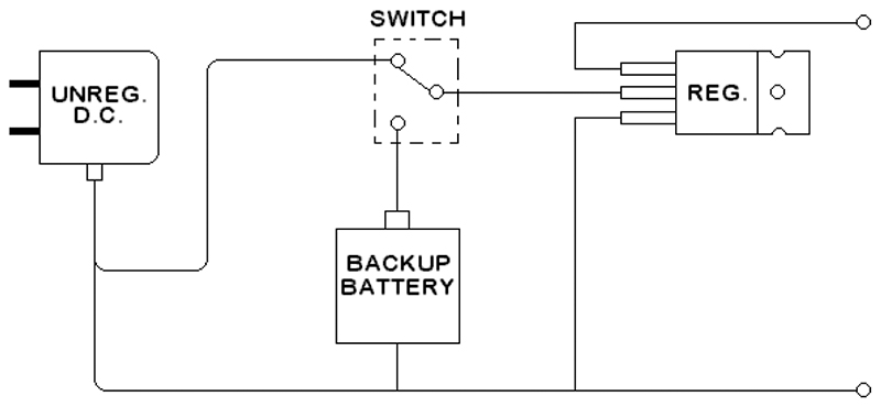
FIGURE 1.
About the Circuit
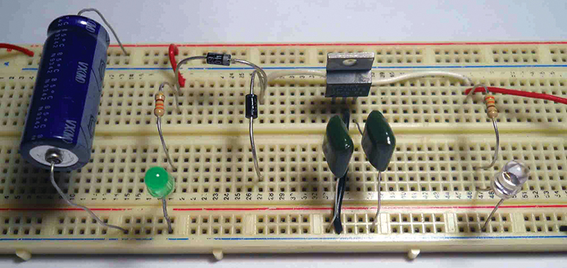
The circuit shown in Figure 2 is a UPS intended for low power applications. It is essentially a linear regulator with battery backup. It provides a regulated 5V DC from an unregulated DC input of at least 9V.

FIGURE 2.
LED1 is the main power indicator. It remains on as long as the regulator is being supplied by the main power source. LED2 is the output power indicator. Taken together, LED1 and LED2 are used to determine the status of the UPS.
Diode D1 isolates the main power source from the backup circuit, while diode D2 comprises the switching logic that will be described later. Capacitors C1, C2, C3, and IC1 form the linear regulator section of the circuit. The battery backup feature can be eliminated from the circuit via switch S1. Note that S1 and S2, as well as LED1 and LED2 — while useful for testing the UPS prototype — are optional and need not be included in your application.
Circuit Operation
The 7805 is a standard linear 5V regulator. It receives input from either the main power source Vs or the backup source Vbb.
Vbb is provided by either alkaline or non-rechargeable lithium batteries. To determine the maximum and minimum values for Vbb, you must consider the forward voltage drop across D1 and D2, as well as the specified minimum input voltage for the 7805, which is 7V.
Let’s assume that the forward voltage drop for D1 and D2 is 1V. If Vs is 9V, then the voltage at the cathode of D2 (and also the input to the regulator) is 8V. Therefore, Vbb can’t be greater than 9V if D2 is to remain reverse-biased. In order to ensure that if Vs fails, the input to the 7805 will be at least equal to the specified minimum, Vbb can’t be less than 8V. If Vs were higher — say 12V — then there would be a wider range for Vbb (8V to 12V).
The 7805 will provide a regulated 5V output for any input voltage from its specified maximum and minimum input voltages. Choosing a value for Vbb that is close to the minimum input voltage can help to extend battery life in situations where Vs may frequently fall between its normal level and the 7805’s minimum input voltage. However, over time, Vbb will fall below its nominal value. If you choose Vbb at or close to its minimum possible value, then this will shorten its usable life. A good choice for Vbb will be a compromise between the specified maximum and minimum values.
Two factors to consider when choosing D1 and D2 are the required load current and the leakage current. If — as in this case — you’re using non-rechargeable lithium or alkaline batteries, you should choose a diode with low leakage current.
We used a 1N5400 diode in our prototype. This diode has a specified maximum reverse (leakage) current of 5 µA at 50V DC (reverse voltage). Its forward current rating is 3A which is more than adequate to deal with the 1.5A maximum output current of the 7805.
Construction
If you intend to use this as a stand-alone power supply, the entire prototype circuit can be assembled on a piece of perf board using point-to-point wiring. Mount the 7805 on a heatsink.
If you intend to incorporate the UPS circuit into your own application, then the backup battery configuration will be a significant factor in your choice of an enclosure.
| ITEM |
DESCRIPTION |
| C1 |
1,000 µF electrolytic capacitor |
| C2, C3 |
0.1 µF capacitor (polyester or mylar) |
| D1, D2 |
1N5400 diode or any diode with a
maximum forward current rating of at least 1.5A
and low reverse leakage current |
| IC1 |
LM7805 (or equivalent) 5V regulator |
| LED1, LED2 |
Light emitting diode (2 mA) |
| R1, R2 |
330 ohm resistor |
| S1, S2 |
SPST switch (optional) |
PARTS LIST.
Prototype Checkout and Troubleshooting
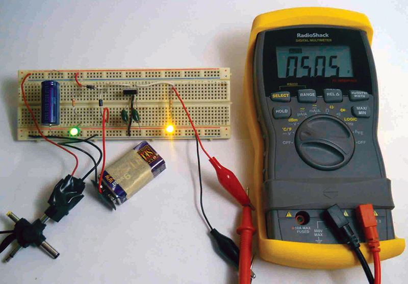
Before powering up the circuit, check all connections. Make sure that you have a DC adapter that can deliver the required maximum current at the required input voltage. Use a fresh battery. With the backup battery out of the circuit, check out the circuit as follows:
- Set S1 and S2 to their open (off) positions.
- Connect the DC adapter to the UPS and plug it into the wall outlet.
- Close S1. Both LED indicators should be on. If neither LED is on, then suspect the adapter and check the voltage across the input to the UPS. Note: The voltage measured at the adapter output when it is not under load will most likely be higher than the rated voltage at the specified load current. For example, the output of the nine volt adapter that I used was 11.2 volts.
- If LED1 is on and LED2 is off, first check the UPS output voltage. If the UPS output voltage is okay, then check LED2 and its limiting resistor. If there is no UPS output voltage, then measure the voltage on the input side of the 7805 regulator. If there is no regulator input voltage, then suspect D1. Otherwise, suspect the 7805.
- If LED1 is off and LED2 is on, then check the wiring for LED1 and its limiting resistor.
- Measure the current between the anode of D2 and ground. It should not exceed the specified leakage current for the diode you have chosen.
- Verify that the regulator portion of your circuit is operating correctly by varying the UPS output load and measure the output voltage. The output voltage should remain relatively constant. Be careful not to exceed the 7805 maximum current limit.
- With S1 still closed, place the backup battery in the circuit.
- Close switch S2 and place S1 in the open (off) position (or remove the adapter from the wall) to simulate a power failure. LED1 should go off. LED2 should remain on.
- Measure the output voltage. It should still be at the regulated level.
The configuration of LED1 and LED2 indicates the status of the UPS and the condition of the main power line. Assuming both S1 and S2 are closed, the status of the UPS is shown in Table 1.
| LED1 |
LED2 |
Condition |
| Off |
Off |
Main power off. No backup battery or low backup battery. |
| Off |
On |
Main power failure. UPS in backup mode. |
| On |
Off |
Main power on. However, UPS has apparently failed.
Possible causes include bad battery, open diode, bad regulator, or bad indicator LED2. |
| On |
On |
Main power on. UPS operating properly. |
| TABLE 1. UPS status conditions assuming switches S1 and S2 are closed. |
Conclusion
There are obviously a number of improvements that you can make to the basic circuit presented here. You can replace the standard 7805 with a variable voltage, low dropout (LDO) regulator. The lower minimum input voltage of the LDO would extend the range of Vbb. Additionally, it can be configured for a range of output voltages. For example, you could use the same part to build a nine volt UPS to power a DC appliance or to design a five volt UPS into your next project.
Another possible improvement would be to replace the linear regulator with the more efficient switching regulator. NV