The real story here is not the circuit, but how you can take a simple circuit and make it into a full blown solution by connecting it to the IoT.
I’m a device maker at heart. What I mean is I love to create dedicated microcontroller solutions that communicate with the real world. Some of my devices have turned into commercial products, but most don’t and my wife ends up enjoying them around the house. Well, I’m not so sure “enjoy” is the correct term … maybe tolerates would be more appropriate.
A while back, I developed a C# application for work that allows a Windows PC to talk directly to a Hue light bulb over the ZigBee HA protocol. My app changed the bulb’s color based on a user’s presence information in Microsoft Lync (Skype for business). If the user was busy, the Hue bulb would be red; if they were available, it would be green, etc.
This project opened my eyes to what is possible when a device is connected to the Internet of Things (IoT). I created this application without any documentation on the Hue bulb. I simply queried the bulb for its capabilities. When asked, the bulb responds back with “I’m a light and I can be turned on or off, my brightness can be changed, and you can change my color.” The device tells me what it can do and how to talk to it!! This is all built into the ZigBee Home Automation public profile.
I couldn’t believe how well designed this was, and read everything I could get my hands on about ZigBee and home automation. I purchased and played around with a few home automation hubs trying to get a feel for how I could use them to control my devices, only to be disappointed on how closed they were. Then, it happened. A dream come true.
I stumbled across a young startup: SmartThings. A home automation platform built for developers from the ground up. They have a cloud-based development environment that allows you to create smart apps and custom device types to talk to, and ... wait for it ... yes, microcontroller-based devices over ZigBee!! They even have an Arduino shield you can use to hack together a prototype.
It was the perfect storm. I had an open platform (SmartThings), an open protocol to talk to it (ZigBee), and years’ worth of awesome Propeller-based devices that could take advantage of it. So, last April, I created a standards-based ZigBee object for the Parallax Propeller that allows my devices to communicate based on the ZigBee HA public profile. It opened a huge door of opportunity for my devices. Now, I can make a device, connect it to the SmartThings hub over ZigBee, and control it with my iPhone. All this and I don’t have to write one line of code that runs on the iPhone!! My device identifies itself to the SmartThings hub, tells it what it is capable of, and the SmartThings hub then determines how to control it.
One of my ZigBee HA projects — the CoopBoss (Chicken Coop Door controller) — won Best in Show at SmartThings. They did a nice write-up on the CoopBoss; if you’re interested, you can check it out at http://blog.smartthings.com/stories/a-smart-chicken-coop.
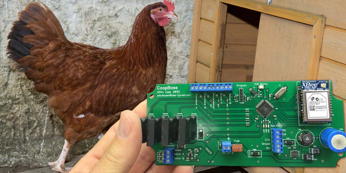
The CoopBoss was a project I put together after my wife lost three of her best hens in a mink attack one night. We forgot to close the coop door and a mink got inside and just ripped three of her five chickens apart. She was heartbroken. Her chickens had been with us for three years supplying my lunch three times a week.
The CoopBoss is a custom printed circuit board (PCB) that drives an off-the-shelf 12V actuator to push the coop’s sliding door closed at sunset and open at sunrise. My wife is able to control it with her smartphone, and can open or close the door anytime, anywhere she has service.
Figure 1 shows the ports to connect the CoopBoss to the real world. They are the following:
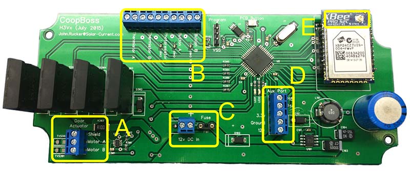
FIGURE 1. CoopBoss Ports.
A - Motor Connection: Connects to a 12V DC linear actuator to push and pull the coop’s door. The motor control circuit has been tested with Progressive Automations’ 12V actuator model number PA-14-12-35. However, just about any 12V DC four amp or less actuator should work.
B - Main I/O Header: This header is connected to two thermistors, one photoresistor, and two normally-open pushbuttons.
C - DC In: 12V DC power in and five amp fuse holder.
D - Aux Port: Auxiliary port for future expansion.
E - Antenna: XBee antenna connection.
Figure 2 highlights the CoopBoss’ onboard modules which include:
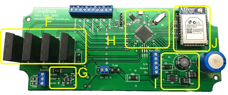
FIGURE 2. CoopBoss Modules.
F - Motor Control: Based on IXYS Integrated Circuit’s CPC1709J solid-state relays. The motor control circuit uses four optically coupled solid-state relays arranged in an H-bridge to drive the 12V DC actuator motor forward and reverse. It is connected to the microcontroller (H) with four I/O pins.
G - Object Detection: Motor current monitoring is based on the Texas Instruments’ INA219BIDCNT bi-directional current/power monitor chip. If the door bumps up against an object during a close, this circuit will detect the small increase in current and quickly relay that to the microprocessor (H) over an I2C bus. The microprocessor will then instruct the motor control circuit (F) to stop closing the door and open back up. This all happens in just a few milliseconds.
H - Microcontroller: The microcontroller is based on the Parallax P8X32A-Q44 multicore Propeller. The Propeller’s multiple core processors are dedicated to monitoring and controlling the various modules of the CoopBoss. For example, to get almost near instant object detection, one processor is dedicated to monitoring the object detection (G) circuit, while the other processors are free to process ZigBee traffic, button I/O, read coop temperature, and monitor the ambient light level.
I - PCB Power Supply: The power circuit is based on the Texas Instruments’ LM2675MX-3.3 switching regulator. It has a very wide input range from 8V to 40V DC and outputs 3.3V DC with up to one amp of current. The power circuit also has a one farad supercapacitor to help regulate the power through high current demands from the motor control circuit (F).
J - ZigBee Radio: The ZigBee radio is from Digi International; the part number is XBP24CZ7UIS-004. This radio securely communicates with the SmartThings hub that connects to the SmartThings cloud on the Internet. A smartphone app (SmartThings Custom Device Type) allows secure control of the CoopBoss over the Internet.

The CoopBoss’ PCB is designed to fit inside a weather-tight aluminum enclosure with weather-tight grommets.
The CoopBoss is a good example of how a reliable circuit can be enhanced by connecting it to the IoT. By adding a ZigBee radio and support for the ZigBee Home Automation profile, the CoopBoss now can have an intuitive user interface accessible from a smartphone anywhere the smartphone has Internet access (Figure 3). By using standard ZigBee clusters with custom attributes, you can do some very slick stuff like add sliders that allow the user to pick the sunlight level for a close or an open. You can even set the sensitivity of the door’s object detection circuit, so if a chicken is in the way, the door will bump up against her and open back up.
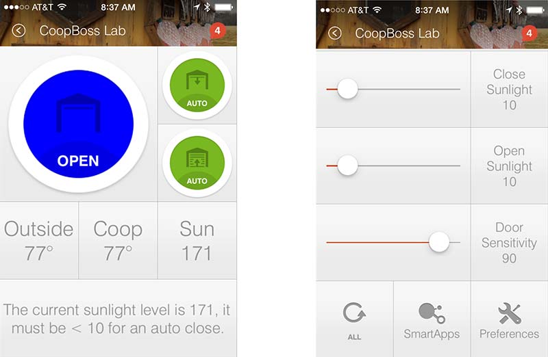
FIGURE 3. Smartphone App.
This project and several others like it have been very rewarding. I would like to share my experiences with focus on the ZigBee communications. The real story here is not the circuit, but how you can take a simple circuit and make it into a full blown solution by connecting it to the IoT. To accomplish this, I have laid out a simple “hello world” test circuit in “The Controlling a Custom Device with SmartThings” section of this article. It’s an LED tied to a Propeller and a ZigBee radio. We will gradually add complexity to the circuit as we go deeper into the protocol.
Why ZigBee?
I would like to take a step back and acknowledge that ZigBee is not the only show in town. Frankly, there is a lot to choose from when it comes down to picking a protocol for IoT communications, but arguably, the big players today are Wi-Fi, Bluetooth LTE, Z-Wave, and ZigBee HA. Almost all the popular home automation hubs support one or all of these protocols. It’s beyond the scope of this article to go into technical detail on each protocol, but I will expand on why I selected ZigBee as the communication standard for my devices.
Self-Configuring, Self-Healing Mesh Network
ZigBee is a mature, open solution based on a self-configuring mesh network. That is important when your device is outside several hundred feet away from your ZigBee hub. If it is too far away to get a good signal, you will have to put a router in to relay the packets and boost the signal. Most mains powered ZigBee devices can be a router.
A router can be something as simple as a Hue light bulb. Once you add the bulb to your network, it will figure out who its neighbors are and start routing packets to them. In fact, that is how we communicate with our chicken coop door controller. We have ZigBee Hue bulbs in our landscaping that carry the traffic to our chicken coop in the back yard.
Strong Application Layer Allowing Devices to Find Each Other and Communicate
In addition to ZigBee’s strong networking layer, it also has a well-defined application layer that describes how common devices can discover each other and communicate. This is what makes ZigBee so attractive for device makers. A great deal of the common actions most devices require are categorized and defined in “cluster” definitions. ZigBee clusters are given 16-bit numbers, often represented as hex numbers. Table 1 is a very small sample of common clusters used by devices.
| Cluster Number |
Description |
| 0x0006 |
On/Off Cluster for devices that can be turned on, off, or toggled. |
| 0x0008 |
Level Cluster for a device that can be dimmed. |
| 0x0101 |
Door Lock Cluster for controlling a door and its lock. |
| 0x0402 |
Temperature Measurement Cluster. |
TABLE 1.
Cluster commands are either a server or client command. For example, say we have a ZigBee enabled light bulb and a ZigBee enabled wall switch. Both devices will communicate using the commands defined in the On/Off (0x0006) cluster. The light bulb will be the server and the light switch will be the client. How the light switch sends the “on” command and how the bulb receives the “on” command are all defined in the On/Off (0x0006) cluster specification.
A ZigBee device supports several clusters or the same cluster several times each on a unique ZigBee endpoint. If you have a device with multiple LEDs to control, each LED’s On/Off Cluster can be on a unique ZigBee endpoint. ZigBee treats the cluster number and endpoint as part of the device’s destination address. This way, you cannot only direct a packet to a device, but to the correct application within the device. We will see examples of ZigBee addressing in a follow-up article when we build out our circuit that controls an LED through a ZigBee Home Automation network.
Why is this important to a device maker? Let’s say you want to make a device that has an LED, and you want to turn the LED on or off remotely. If your device follows the guidelines detailed by the On/Off Cluster, then your device can be controlled by the exact same ZigBee enabled wall switch discussed above. Let’s take that one step further. Replace the ZigBee enabled wall switch with a smartphone application. Say you have an existing home automation solution with a smartphone application that controls your ZigBee enabled lights (like SmartThings). Since your LED device adheres to the ZigBee On/Off cluster commands, it is now possible to control the LED by that same smartphone app! Your device just joined the Internet of Things!
You have all the power of that slick smartphone app without writing one line of custom code for your smartphone! Not only can you control your LED from your smartphone, it can also be part of your home automation. So, if you have your home automation rules set up to turn on your lights when you pull into your garage, your LED can come on as well.
Controlling a Custom Device with SmartThings
This project is going to focus on the radio hardware setup and communications required to talk to a ZigBee HA network hub (SmartThings) over ZigBee standard Clusters. We will use a Propeller microcontroller connected to a Digi XBee ZB radio to communicate with the hub. The circuit is simple and you can use any number of existing Propeller prototype boards.
To play along, you will need some hardware. Here are a couple of options:
Option 1) is a custom PCB and a link to the parts you can order to populate it (requires soldering);
Option 2) is a list of parts you can order to work with one of your existing Propeller project boards (refer to Tables 2 and 3). There is an additional parts diagram for the PCB in the downloads at the end of this article.
TABLE 2. Option 1
TABLE 3. Option 2
Step 1) Configure Your XBee to Join a ZigBee Home Automation Network.
Each ZigBee profile has stringent security requirements that must be met before a device is allowed to join a network. Your SmartThings hub uses the ZigBee Home Automation profile security model, so we will need to configure our radio to meet those specs. To make a ZigBee network secure, each network generates its own unique network encryption key used to encrypt network packets. Your device must have this key to communicate, and that is all taken care of during the network “join” process.
The ZigBee coordinator’s (SmartThings hub) primary role during a join is to give your radio the network key and allow it to join the network. To get the network encryption key from the coordinator, our radio must be configured with the proper trust center link key. Think of it as a password you must give the coordinator before it will give you the network encryption key.
FIGURES 4 & 5.
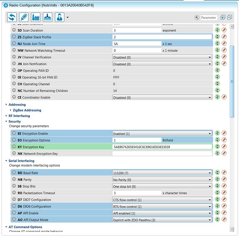
FIGURE 6. Digi's XCTU XBee Configuration Tool.
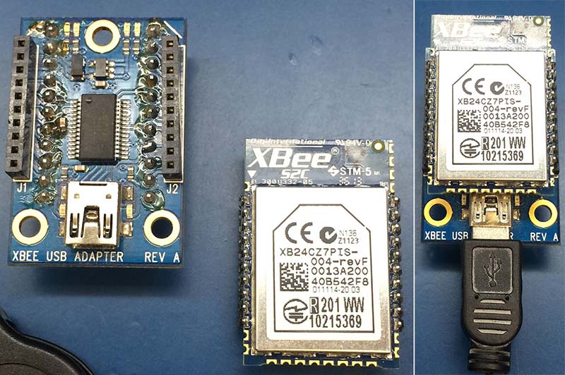
To configure your XBee radio, you will need to plug the XBee into your computer with the XBee USB adapter board. If you haven’t done so, assemble your XBee USB adapter board and Load Digi’s XCTU software. You can download it from www.digi.com/products/xbee-rf-solutions/xctu-software/xctu. You will also need to download the XBee’s configuration file (Nuts&Volts_xBee.xml) available at the article link, and save it to your local hard drive. Using the XCTU software, load the configuration file from your local hard drive and write it to your XBee. (Refer to Figures 4, 5, and 6.) This configuration file sets the parameters shown in Table 4.
| Cmd |
Setting |
Description |
| ZS |
0x2 |
Set ZigBee stack to 2 |
| NJ |
0x5A |
Set network join time to 90 seconds |
| EE |
0x1 |
Enable the use of encryption keys |
| EO |
0x1 |
1 = Use trust center to get network key |
| KY |
0x5A6967426565416C6C69616E63653039 |
This is the trust center link key |
| BD |
0x7 |
Set baud rate to 115200 |
| D6 |
0x1 |
Turn on RTS flow control |
| AP |
0x1 |
Enable API mode |
| AO |
0x3 |
Explicit API mode with ZDO pass-through |
TABLE 4.
Once this step is complete, your radio is programmed to join any ZigBee HA network; you won’t have to do this again. As soon as you reset your radio, it will start looking for an open ZigBee HA network to join. To allow it to join the network, you will need to tell SmartThings to open the network and allow a new device to join. (More on this later. For now, you can unplug your radio and move on to the next step.)
Step 2) Build Your Circuit.
The sample code outlined in the next step is designed to work with the schematic in Figure 7. If you’re building your own circuit, you don’t have to worry about connecting your XBee, LED, and pushbutton to the same pin numbers shown here. We can configure that in the code.
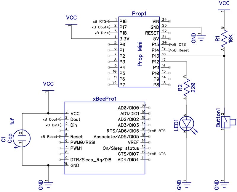
FIGURE 7. ZB-LED PCB for Propeller Mini.
Please note, we connect the Propeller to the XBee with five pins: Dout, Din, Reset, CTS, and RTS. We need all five pins as we are going to implement hardware handshaking to the XBee. If we had to, we could get by without the XBee’s “reset” pin, but without it you may find yourself power cycling your circuit from time to time.
On pin 12 of the Propeller Mini, we connect an LED and a 220 ohm current-limiting resistor. This is the LED we will control with SmartThings.
On pin 13 of the Propeller Mini, we connect a 10K ohm pull-up resistor and pushbutton to ground. This button will also be used to control the LED and send commands to SmartThings.
Now that you have your circuit built, you can transfer your XBee Pro from the USB programmer to your new circuit and continue on to the next section about loading the firmware. If you’re using the ZB-LED PCB (Figure 8), make sure you plug in your XBee as shown.
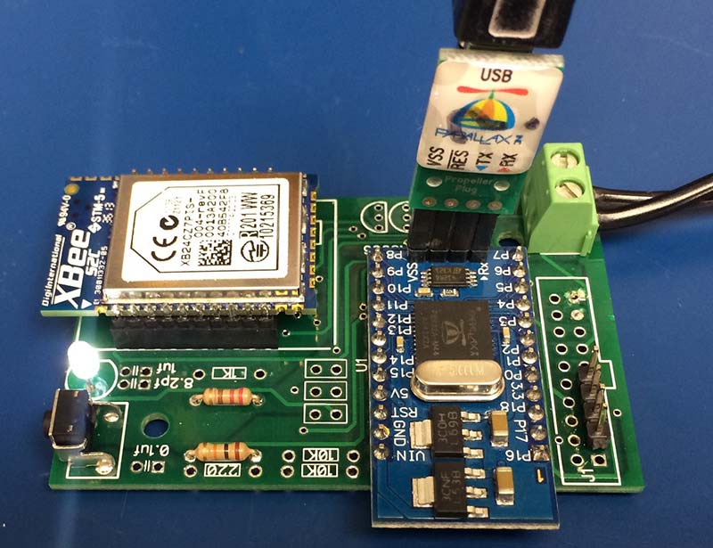
FIGURE 8.
Step 3) Loading the Propeller Firmware.
Load the zB_LedDemoA2.Spin program from the downloads and configure the pin assignments for your circuit. If you’re using the ZB-LED PCB, the pin assignments will be correct (Figure 9).

FIGURE 9.
Once you have the pins set correctly, save the settings and then load the program (zB_LEDDemoA2.SPIN, also at the article link) to the Propeller’s EEPROM. Bring up the Parallax Serial Terminal and cycle the power to your circuit. You should see the Propeller boot up and start looking for a ZigBee Home Automation network to join as shown in Figure 10. The two letter hex codes are what the XBee’s AI (Association Indication) parameter is reporting. Table 5 is from page 148 of the XBee/XBee-PRO ZB SMT RF Modules documentation and it details the two letter hex codes. What you should see are the hex numbers 0xFF and 0x23 repeated over and over.
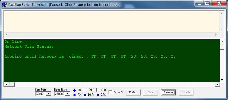
FIGURE 10.
| AI Code |
Description |
| 0x00 |
Successfully formed or joined a network. (Coordinators form a network; routers and end devices join a network.) |
| 0x21 |
Scan found no PA. |
| 0x22 |
Scan found no valid PANs based on current SC and ID settings. |
| 0x23 |
Valid coordinator or routers found, but they are not allowing joining (NJ expired). |
| 0x24 |
No joinable beacons were found. |
| 0x25 |
Unexpected state; node should not be attempting to join at this time. |
| 0x27 |
Node joining attempt failed (typically due to incompatible security settings). |
| 0x2A |
Coordinator start attempt failed 0x2B — checking for an existing coordinator. |
| 0x2C |
Attempt to leave the network failed 0xAB — attempted to join a device that did not respond. |
| 0x2AC |
Secure join error — network security key received unsecured. |
| 0x2AD |
Secure join error — network security key not received. |
| 0x2AF |
Secure join error — joining device does not have the right preconfigured link key. |
| 0x2FF |
Scanning for a ZigBee network (routers and end devices). |
TABLE 5.
The XBee radio will look for a network to join that matches its security settings. Every time you see “FF” displayed on the screen, it is searching on a new channel; “23” means it found a valid coordinator but it is not allowing it to join at this time. To allow our device to join, we have to open the network for joining. Proceed to the next step to join the SmartThings network.
Step 4) Connect to SmartThings.
If you haven’t set up your SmartThings hub and downloaded their smartphone app, you need to do that now.
FIGURES 11 &12.
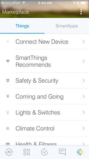
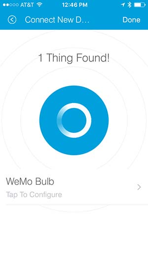
From your smartphone, open the SmartThings app (Figure 11) and go to the Marketplace; scroll until you see “Connect New Device” as shown in Figure 12. Tap on “Connect New Device” to tell SmartThings to open the network and let new devices join. After a few minutes, you should see the WeMo Bulb pop up on the bottom part of your smartphone’s screen (Figure 12). We are impersonating that device and you can tap to configure it and change its name to “My LED” or just tap “Done” to accept the defaults.
Back on your Parallax Serial Terminal screen, you will notice that ZigBee packets are starting to flow as shown in Figure 13. Your device has joined the SmartThings Home Automation network and now can be controlled with your smartphone.
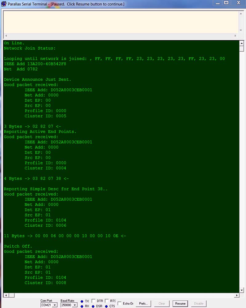
FIGURE 13.
Find your WeMo Bulb or, in our case, “My LED” in your things listing from the dashboard, and tap on the icon to turn the LED on and off.
Bang! Your LED will turn on and off as you push the button (Figures 14 and 15). Since SmartThings is cloud-based, you will be able to take your smartphone anywhere you have cell phone or Wi-Fi signal and control your LED.
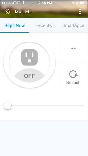
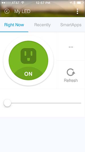
FIGURES 14 & 15.
In a follow-up article, we will walk through the code details of what’s going on behind the scenes and add more functionality to our device by adding support for the Level Cluster that will allow us to dim the LED, and ZigBee binding that will allow us to push the button and change the status of our LED in SmartThings in real time. NV
CoopBoss ZigBee Configuration. List of the endpoints and clusters used by the CoopBoss.
| ZigBee Custom Attributes |
| $0400 |
Custom Attribute for Current Light RC Time value, type 0x23 |
| $0401 |
RC Time value that will trigger a door close, type 0x23 |
| $0402 |
RC Time value that will trigger a door close, type 0x23 |
| $0403 |
Read Auto Door Close Setting 0=Disabled, 1=Enabled, type 0x10 |
| $0404 |
Read Auto Door Close Setting 0=Disabled, 1=Enabled, type 0x10 |
| $0405 |
Current of last door close |
| $0406 |
Seconds to next close window |
| $0407 |
Seconds to next close window |
| $0408 |
Object detection sensitivity (1 to 100) 1 = very sensitive |
| $0409 |
Read Normal Door Current Setting |
| ZigBee End Points |
| 0x38 |
Input Cluster |
0x0000 |
Basic Cluster |
| |
Output Cluster |
0x0101 |
Door Lock Cluster |
| |
Output Cluster |
0x0402 |
Temperature Cluster (Temperature of XBee radio) |
| 0x39 |
Input Cluster |
None |
N/A |
| |
Output Cluster |
0x0402 |
Temperature Cluster (Coop Probe 1) |
| 0x40 |
Input Cluster |
None |
N/A |
| |
Output Cluster |
0x0402 |
Temperature Cluster (Coop Probe 2) |
| ZigBee Cluster 0x0101 Attributes |
| $0000 |
Read LockState; see page 344 of ZCL, type 0x30 $30 = eight-bit enumeration |
| $0001 |
Read LockType; see page 344 of ZCL, type 0x30 |
| $0002 |
ActuatorEnabled; see page 344 of ZCL, type 0x10 |
| $0003 |
Read DoorState; see page 344 of ZCL, type 0x30, Reportable |
| ZigBee Custom Commands for Cluster 0x0101 |
| $0A |
Enable Auto Close Door |
| $0B |
Disable Auto Close Door |
| $0C |
Enable Auto Close Door |
| $0D |
Disable Auto Close Door |
| $0E |
Set Close Light Level to Current Level |
| $0F |
Set Open Light Level to Current Level |
| $10 |
Set Close Light Level (to Long Value) |
| $11 |
Set Open Light Level (to Long Value) |
| $12 |
Set Auto Close and Open Light Levels back to factory |
| $13 |
Set Normal Door Close Current to value of Last Door Close Current |
| ZigBee Cluster 0x0101 commands |
| $00 |
Close Door |
| $01 |
Open Door |
| $03 |
Toggle Door Lock |
| $04 |
High Current Door Close |