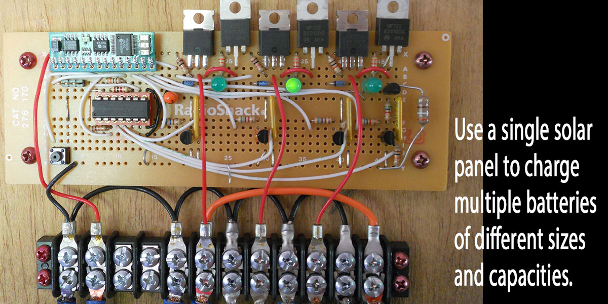
This article describes how to build a solar sequencer which enables a single solar panel to charge multiple batteries of different sizes and capacities, keeping them isolated from each other. This article also covers how to use a solar panel and battery to run a garage door opener in a building without access to utility power. The Solar Sequencer provides a maintenance charge to 12 volt lead acid automotive batteries from a 45W solar panel. My unit has been in operation for three years now.
Solar Panel
The solar panels are from Harbor Freight’s 45 watt solar panel kit. The panels face due south and are mounted at 30 degree angles to each other in order to spread the capacity over as much of the day as possible. If they are mounted as shown in the kit directions, the current can be over three amps at noon, but not much in the morning and evening. The mount was made out of 1" aluminum angle purchased from the hardware store.
Garage Door Opener
The garage door opener I used is a Craftsman/Chamberlain belt drive with a battery backup. It is designed to run from a 12 volt 5 Ah lead acid battery (included), but only as a backup. Everything but the lights work with no AC power, and it draws about 40 mA when in standby. It does need AC power applied initially, but will work from the battery afterward. I used a long extension cord at first, but switched to a cheap 400 watt modified sine wave inverter to get it started, then disconnected the inverter. This garage door opener uses four amps DC to open the door and 3.5 amps to close it. Both take about 20 seconds.
Battery
The small battery included with the garage door opener only lasts about six months. It is only intended as a backup — not a primary power source. I replaced it with a lead acid battery that was still good but out of warranty, which I removed from a Jeep Grand Cherokee. It is a size 26 battery which has a standby power number of 150, meaning it can supply 25 amps for 150 minutes. I plan to add another opener and this should be more than enough to power both. It also can run the lights that came with the solar panel kit. The Jeep's battery is on a shelf in the back of the garage and wired to the garage door opener with 14 gauge wire.
Hardware
Figure 1 shows a photo of the prototype that is still in operation. (The circuit is simple enough to build and use on a prototyping board.) Figure 2 is a printed circuit board (PCB) version that is more professional looking and easier to hook up.

FIGURE 2. Printed wiring board version.
Figure 3 is the schematic, and Figure 4 shows a wider angle with the sequencer connected to the garage door opener, garage battery, truck, and ATV.
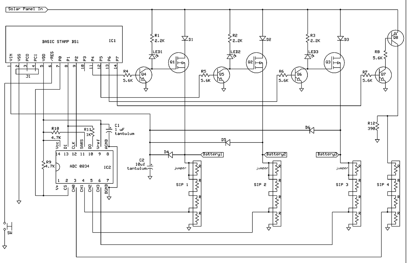
FIGURE 3. Schematic.

FIGURE 4. Garage installation (note circles which show locations of system components).
I chose the Parallax BASIC Stamp 1 microcontroller, mainly because I had one from another project and it is easy to use. It also has an onboard regulator, brown-out circuitry, and a reset input pin. The Stamp reads an 0834 Analog-to-Digital Converter (ADC) which is covered in the BASIC Stamp applications manual.
Because the ADC inputs can only measure up to five volts, the battery voltage is divided by three, using a resistor divider with an isolated 10K eight-pin Single In-line Package (SIP) resistor network. Since the resistors in the SIP are made using the same process, their values are all very close to each other. The tolerance is 2%. This can also be done with discrete resistors, but with less accuracy unless the resistors are matched.
This load is on the battery all of the time; the current draw should be as low as possible. I used a 10K SIP — with three of the resistors in series — which uses 0.45 mA (13.5/30K). A higher value SIP resulted in less accurate readings due to the higher input impedance on the ADC input. The open circuit voltage of the solar panels can be as high as 23 volts; the ADC input for them is divided by four. It uses all four resistors in the SIP. During the load test of the solar panels, dividing by four keeps the voltage on the ADC input less than five volts. Power for the Stamp and ADC is supplied by the battery(s) through diodes D4, D5, or D6. That way, it doesn't matter which output is connected to a battery or left open.
Power Circuit
In order to reference the ADC to ground, P-channel MOSFETs (Q1, Q2, and Q3) are used. The MOSFETs need very little current to be turned on, and have a very low on resistance. It is a P-channel IRF 5305 which has a built-in bypass diode. The bypass diode will allow a charged battery to push current to a charging battery when the MOSFETs are off. The purpose of diodes D1, D2, and D3 is to block this current. They are Schottky MBR2535CTs which have a lower voltage drop than standard diodes. The diodes are rated for 30 amps, and the MOSFETs are rated for -31 amps. The MBR2535CT has two diodes in a TO-220 package — both of which are used in parallel.
Cheaper components with less current handling capability could be used — especially for a lower capacity panel — but a MOSFET with a low on resistance typically has a high current rating. I originally thought this could be used with a 120 VAC charger capable of 10 amps, but never used it that way other than for testing. The voltage drop across the diode and MOSFET is less than 0.5V, and most of that is across the diode. Since the maximum current is less than two amps, neither device requires a heatsink.
Each particular MOSFET is turned on by the Stamp 1 using a 2N3904 NPN transistor, along with the charging LED. The LED is not very bright because the 2.2K resistor sets the current at about 5 mA, which is a trade-off between being able to see it and current consumption. I also considered using a PNP power transistor and using the base current to light the LED, but the on resistance was high. A relay would work too, but the coil current is wasted and rather high. The MOSFET is ideal for this application.
Software
The details of the code (available in the downloads at the end of this article) are included in the code comments, but here is a brief summary of how it works. When the program starts, the Charge routine load-tests the solar panel capacity by turning on Q4, which causes about 30 mA to flow through the 390 ohm resistor. This value was chosen only because it is close to the standby current of the garage door opener. If the ADC reading is greater than the startCharge value (13 volts), the Charge1 routine is executed. If not, it calls Night which sleeps 10 minutes and tries again. The Charge1 routine checks the first battery. If it is less than 13 volts but greater than 10 volts, it calls the ChargeLoop subroutine. If not, it checks the next battery. Since the battery voltage drops very slowly, at the end if none of the batteries have been charged, it waits for a minute then executes again. ChargeLoop is called if any of the batteries need to be charged, and it turns on a MOSFET allowing the solar panel to charge the battery. It checks the voltage every five seconds until the voltage is greater than stopCharge (14.2 volts), then turns off the MOSFET and returns to the Charge routine.
The ChargeLoop subroutine also stops charging approximately every 20 minutes, load-tests the solar panel capacity, and (if it is still high enough) resumes charging. If not, it calls the Night routine and sleeps for 10 minutes. The Stamp uses very little power during sleep.
Construction
The prototype circuit was constructed on a RadioShack prototyping board (as shown in Figure 1). It is simple enough to build with point-to-point wiring. I soldered a wire over the circuit trace at the top that carries the solar panel current (because it isn't intended to carry much current). I also covered the entire trace with solder between the MOSFET and the wire leading to the barrier strip.
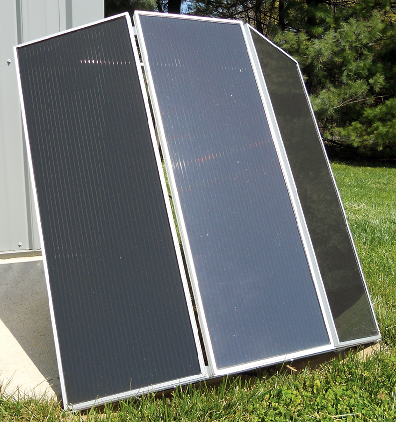
FIGURE 5. Solar panel setup.
The input from the solar panel and output to the battery(s) is wired to a barrier strip. All of the ground leads are connected together on the barrier strip. From that strip, the truck's battery is connected with the same type of large clamps that an AC charger uses. The ATV and lawn mower use cigarette lighter plugs.
Be extra careful when making these connections, since lead acid batteries can push a lot of current and burn up components — not to mention cause a fire.
The layout of the parts on the board is the same as shown in the schematic. There are a few traces that are cut between the Stamp and ADC. Pins P1 and P2 on the Stamp line up with pins 13 and 12 on the ADC; the other traces between those two components were cut. Traces between SIP pins were also cut; refer to the schematic and cut where there is no connection between pins. The two terminals on the right of the barrier strip are really not needed, so I used them to connect to a cigarette lighter socket; the orange wire connects it to the garage battery. This socket is used to power a 12V trouble light from the garage battery. There are two pushbutton switches on the left in Figure 1. The lower one is connected to the Stamp reset pin; the upper one isn't used and not necessary (it's left over from an earlier design).
The six-pin SIP I used on the prototype isn't available from Jameco anymore; the one on the Parts List has four resistors (eight-pin).
PARTS LIST
| ITEM |
DESCRIPTION |
QTY |
SOURCE |
| IC1 |
BASIC Stamp 1 |
1 |
Jameco 127693 |
| IC2 |
ADC 0834 |
1 |
Jameco 1252331 |
| Q1, Q2, Q3 |
IRF 5305 |
3 |
Jameco 1559965 |
| D1, D2, D3 |
MBR2535CT |
3 |
Jameco 618097 |
| Q4, Q5, Q6, Q7 |
2N3904 NPN |
4 |
Jameco 178597 |
| Q8 |
2N3906 PNP |
1 |
Jameco 178618 |
| D4, D5, D6 |
1N4001 |
3 |
Jameco 35975 |
| LED1, LED2, LED3 |
LEDs (yellow) |
3 |
Jameco 34825 |
| C1 |
1 µF tantulum |
1 |
Jameco 94388 |
| C2 |
10 µF tantalum |
1 |
Jameco 94080 |
| SIP1, SIP2, SIP3, SIP4 |
10K isolated SIP |
4 |
Jameco 856909 |
| R1, R2, R3 |
2.2K 1/4 watt |
4 |
|
| R4, R5, R6, R7, R8 |
5.6K 1/4 watt |
5 |
|
| R9, R10 |
4.7K 1/4 watt |
2 |
|
| R11 |
1K 1/4 watt |
1 |
|
| R12 |
390 1/2 watt |
1 |
|
| SW |
Pushbutton switch |
1 |
Jameco 153252 |
| J1 |
Pin header |
1 |
Jameco 103393 |
| Barrier Strip |
Eight-position |
|
|
| OR |
|
|
|
| Connector Terminal Block |
Two-position |
1 |
Jameco 152347, 5.08 mm |
| Connector Terminal Block |
Three-position |
2 |
Jameco 152355, 5.08 mm |
| 16 or 14 gauge red/black DC power wire |
| Battery clamps or cigarette lighter plug |
The schematic shows how the first resistor is just shorted out on the battery dividers.
The circuit board and barrier strip are mounted on a piece of 1/4” plywood. The blister pack that the RadioShack prototyping board comes in can be used as a cover for the circuit board by cutting some slots in the top for the diode and MOSFET tabs to go through.
The printed wiring board is the same basic schematic but the layout is different, and the solar panel and batteries are connected to it with a separate terminal strip. Although I made various mistakes on this version, it still works fine. An improved design has the screw terminal blocks mounted directly on the board, with no separate barrier strip to mount and wire. It also has an LED driven by the Stamp pin P3 that is on when there is enough solar panel capacity but none of the batteries are charging. That way, the only time there is no LED lit is when the Stamp is in the sleep state.
Testing and Operation
The solar panel is connected to the solar input, and a lead acid battery is connected to one of the battery outputs; double-checking the positive and negative connections. Connect wires to the barrier strip first, then connect to the battery. If the battery voltage is less than 13V, the LED for that battery output will light. If the LED does not light and the battery voltage is above 13V, connect a load such as an automotive light bulb to the battery. If the battery is in a vehicle, opening the door will load it when the interior lights turn on. This will usually lower the voltage enough that the LED will light. Close the door or remove the load.
Once the battery voltage is above 14.2V, the LED will turn off. This will happen rather quickly if the battery is near full charge on a sunny day. This procedure is repeated for the other battery outputs. For operation, connect the other batteries to the barrier strip first, then the battery, and let the sun do the rest. To get the garage door opener working, connect its battery power leads to a 12 volt lead acid battery (it uses 1/4" female quick connectors) and the battery to the solar sequencer. It won't come on unless it is plugged into AC power. Connect a power inverter to the battery and plug the garage door opener into it, or use a long extension cord (or generator) to plug into AC power. I used a 400 watt inverter, but 100 is probably enough as long as it doesn't have to open the door. The garage door opener's LCD display will show "charging battery."
Unplug it and it will continue to run on the battery. The display will still alternate between time and temperature, and the time can still be set. The only things I don't like are the display always scrolls "battery backup enabled" across the bottom; if the voltage drops below 12.5, it will beep every minute, and there is an orange LED on all of the time. The lights also don't work — they need AC power — but the Harbor Freight solar panel kit comes with two nice 12 volt fluorescent lights that can be wired up separately (just not turned on by the garage door opener). I have been using the prototype version of this design with the garage door opener for a year now, but only for six months with the Jeep's old battery. It was a fun project, and a great way to use solar energy to power the garage. NV
The Parts List is slightly different for the PCB version. There are terminal blocks on it and an extra 2N3904 transistor, LED, and 5.6K and 2.2K resistors. Those parts are not on the schematic, since they were added onto the PCB only and are not on the prototype board, either. It will still work fine without them. A PCB for this project is available in the Nuts & Volts Webstore (Solar Sequencer PCB).