The so-called chaser or sequencer is one of the most popular types of LED-driving circuit and is widely used in advertising displays and in running-light ‘rope’ displays in small discos, etc.
It consists — in essence — of a clocked IC or other electronic unit that drives an array of LEDs in such a way that individual LEDs (or small groups of LEDs) turn on and off in a predetermined and repeating sequence, thus producing a visually attractive display in which one or more ripples of light seem to repeatedly run through a chain or around a ring of LEDs.
The 4017B CMOS IC is probably the best known and most widely used LED-driving IC used in chaser/sequencer applications. This article looks at a variety of practical circuits based on this particular IC.
4017B BASICS
The 4017B is a member of the popular ‘4000B’ family of CMOS digital ICs and can use any DC supply voltage in the 3V to 15V range. It is actually a clocked decade counter/divider IC with 10 fully decoded short-circuit-proof outputs that can each be used to directly drive a simple LED display. If desired, various outputs can be coupled back to the IC control terminals to make the device count to (or divide by) any number from two to nine and then either stop or re-start another counting cycle.
Numbers of 4017B ICs can be cascaded to give either multi-decade division or to make counters with any desired number of decoded outputs. The 4017B is thus an exceptionally versatile device that can easily be used to chase or sequence a basic LED display of virtually any desired length.
Figure 1 shows the outline, pin notations, and basic functional diagram of the 4017B, and Figure 2 shows the waveform timing diagrams of the IC, which incorporates a five-stage Johnson counter and has CLOCK, RESET, and CLOCK INHIBIT input terminals.
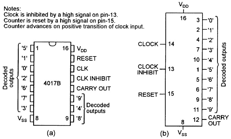
FIGURE 1. Outline and pin designations (a) and basic functional diagram; (b) of the 4017B decade counter/divider IC.
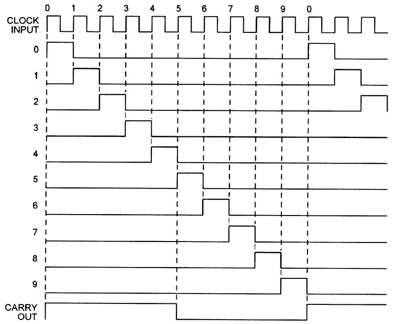
FIGURE 2. Waveform timing diagram of the 4017B with its RESET and CLOCK INHIBIT terminals grounded.
The internal counters are advanced one count at each positive transition of the input clock signal when the CLOCK INHIBIT and RESET terminals are low. Nine of the 10 decoded outputs are low, with the remaining output high, at any given time. The outputs go high sequentially, in step with the clock signal, with the selected output remaining high for one full clock cycle. An additional CARRY OUT signal completes one cycle for every 10 clock input cycles, and can be used to ripple-clock additional 4017B ICs in multi-decade counting applications.
Note that the 4017B counting cycle can be inhibited by setting the CLOCK INHIBIT terminal (pin 13) high, and that a high signal on the RESET terminal (pin 15) clears the counter to zero and sets the decoded ‘0’ output terminal (pin 3) high.
A 4017B LED-DRIVING TEST CIRCUIT
The 4017B is a versatile and easy-to-use IC and (like most 4000B-series ICs) has short-circuit-proof outputs that exhibit slightly surprising characteristics when driving LED-type loads. Figure 3 shows a practical 4017B test circuit that can be used to demonstrate the IC’s basic actions and output-driving characteristics. The circuit is best built on a ‘plugblock’ type of breadboard unit, in which components and wires are simply pushed into the unit’s sprung-contact blocks.

FIGURE 3. A 4017B LED chaser/sequencer test and demonstration circuit.
In Figure 3, the 555 timer IC (IC1) is used as a variable-frequency asymmetrical squarewave generator that feeds clocking signals to the CLK input terminal of the 4017B IC (IC2). This output waveform is normally high, but briefly flips low once per cycle and drives LED5 on. The 4017B’s internal switching actions are initiated as this signal flips high again and LED5 switches off. Note that the clocking signal is fed to the 4017B IC via removable Link A, and can thus be physically interrupted whenever required; R4 and R5 protect the 4017B’s input against damage when Link A is open or IC2’s positive supply connection is broken.
In Figure 3, the positive DC supply line is connected to pin 16 of the 4017B IC via an external multi-range DC current meter that (since IC2’s quiescent current is negligible) gives a direct readout of the current drawn by the IC’s currently-active output load. The 4017B is wired (via pins 10 and 15) in the ‘divide-by-four’ mode and sequentially drives four sets of output loads, which are notated ‘0’ to ‘3.’
Output ‘0’ takes the form of a single LED when Link B is open, or a short-circuit when Link B is closed. Output ‘1’ takes the form of a single LED. Output ‘2’ takes the form of two series-connected LEDs. Output ‘3’ takes the form of three series-connected LEDs. All LEDs are red high-brightness types.
When construction of the Figure 3 circuit is complete, close Link A, open Link B, connect the meter in place, and connect the unit to a 9V DC supply. Adjust RV1 to give a slow clocking rate, noting that LED5 gives a brief flash during each cycle, and that all other LEDs or groups of LEDs activate sequentially. You will probably be surprised to note that all of the display LEDs (LEDs 1 to 4) operate at almost equal brightness, and that all output loads produce fairly similar current readings on the test meter.
When testing the Figure 3 circuit, you can check the individual load currents by waiting until the load activates and then ‘freezing’ the display by opening Link A. When load ‘0’ is active, the load current is typically 17.5mA with Link B open or 19mA with Link B closed; the load ‘2’ and load ‘3’ currents are typically 16mA and 12.5mA, respectively. Thus, when using a 9V supply, the load current is typically 19mA when driving a short-circuit, or 12.5mA when driving three series-connected red LEDs. The graphs of Figures 4 and 5 help explain this circuit action.
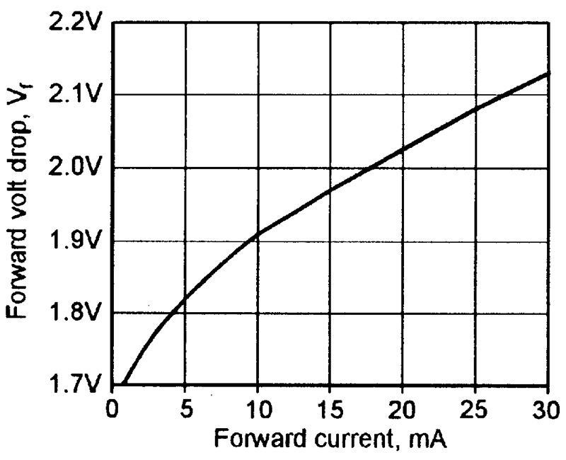
FIGURE 4. Typical forward current/voltage graph of a high-brightness red LED.
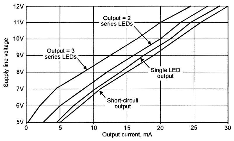
FIGURE 5. Typical supply voltage versus output current graph of the Figure 3 circuit when driving different types of loads.
Figure 4 shows the typical forward current/voltage graph of a high-brightness red LED. Note that large variations in forward current produce relatively small variations in forward voltage. Thus, when the current is increased from 10mA to 30mA, the forward voltage increases by only 0.22V and, in this case, the LED thus acts like a pure voltage (zero impedance) load in series with an 11-ohm impedance. In practice, this impedance varied between 10 and 15 ohms over most of the LED’s working current range.
Figure 5 shows the typical supply voltage versus output current graph that applies to each output of the Figure 3 circuit when driving different types of loads.
Note that each CMOS output stage acts like a loosely-controlled constant-current generator that has its short-circuit output current determined by the supply voltage value, but has its LED-driving current value influenced by the actual Vout value of the stage.
In the Figure 3 circuit — when using a 9V supply — Vout is zero when driving a shorted output and, under this condition, 9V is developed across the output stage, Iout is 19mA, and 171mW is thus dissipated in the output stage. When, on the other hand, the 9V circuit is driving three series-connected LEDs, Iout is 12.5mA, Vout is 5.85V (see Figure 4), 3.15V is developed across the output stage, and less than 40mW is thus dissipated in the output stage.
Note that most 4000B-series CMOS data sheets list the maximum permitted DC power dissipation values of the 4017B IC as 100mW per-output-stage and 500mW per-package, and these figures should be kept in mind when experimenting with the Figure 3 test/demonstration circuit.
PRACTICAL 4017B CHASER/SEQUENCER CIRCUITS
Figure 6 shows the practical circuit of a 4017B 10-LED chaser in which IC1 acts as a variable-rate clocking generator and the 4017B IC is wired into the decade counter mode by grounding its CLOCK INHIBIT (pin 13) and RESET (pin 15) control terminals. The circuit action is such that the visual display appears as a moving dot that repeatedly sweeps from the left (LED0) to the right (LED9) in 10 discrete steps as the 4017B outputs sequentially go high and drive the LEDs on. The LEDs do not, of course, have to be connected in a straight line; they can, for example, be arranged in a circle, in which case, the circle will seem to rotate.
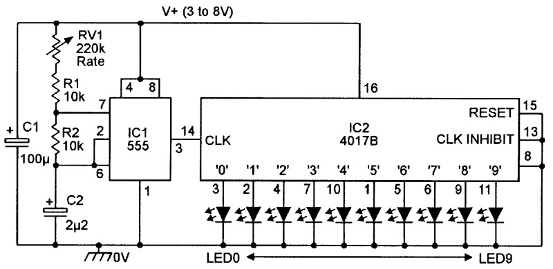
FIGURE 6. A 10-LED chaser/sequencer can be used with supply voltages up to only 8V and produces a moving dot display.
Note that the Figure 6 circuit relies on the internal action of the 4017B to limit the LED currents to safe values, and this circuit can thus be safely used with supply voltages up to a maximum of only 8V without risk of exceeding the IC’s 100mW per-output-stage power dissipation limits.
Figure 7 shows a modified version of the above circuit, in which a current-limiting 470-ohm resistor is wired in series with each LED to help reduce the IC’s power dissipation to a safe level. This circuit can use any DC supply in the 6V to 15V range.
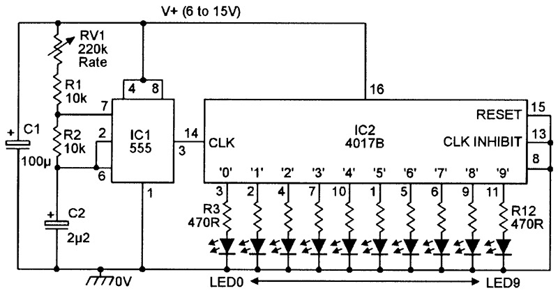
FIGURE 7. This version of the 10-LED chaser can be used with any supply up to 15V.
Figure 8 shows a circuit variant in which the LEDs share a single current-limiting resistor (R3) and which can be used with reasonable confidence at supply values up to 12V maximum. Figure 9 shows a possible equivalent of this circuit when it is powered from a 15V supply and which illustrates the limitation of the design.
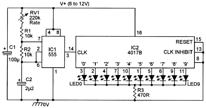
FIGURE 8. This version of the chaser can be used with supplies up to 12V maximum.
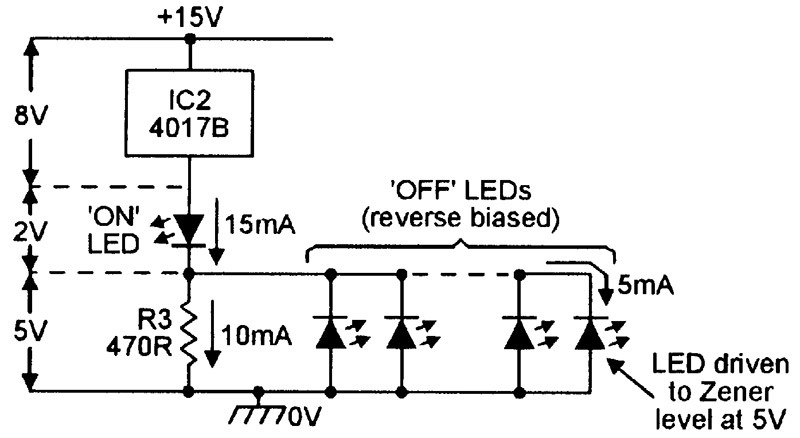
FIGURE 9. Possible equivalent of the Figure 8 circuit when powered from a 15V supply.
The action of the 4017B is such that, when a given LED is on, it effectively grounds the anodes of all other LEDs; R3 thus causes the ‘off’ LEDs to be reverse biased. Because of the low reverse-voltage ratings of LEDs, this action can cause one or more of the ‘off’ LEDs to zener at about 5V, thus giving the results shown in the diagram and possibly causing a power overload in the IC’s active output stage.
Thus, when the 4017B is used to drive simple ‘one-LED-per-output’ displays in the moving dot mode, the LEDs can be connected directly to the IC outputs if supply values are limited to 8V maximum, but at supply voltages greater than 8V, the LEDs must be connected to the IC outputs via current-limiting resistors. A variety of alternative types of 4017B LED display circuits are shown in Figures 10 to 15.
ALTERNATIVE LED DISPLAYS
The output stages of the 4017B can source or sink current with equal ease. Figure 10 shows how the IC can be used in the sink mode to make a moving hole display in which nine of the 10 LEDs are on at any given time, with single LEDs turning off sequentially. If the LEDs are wired in the form of a circle, the circle will seem to rotate. Note that, since all LEDs except one are on at the same time, each LED must be provided with a current-limiting resistor, to keep the IC power dissipation within safe limits.
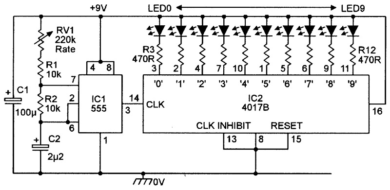
FIGURE 10. A 10-LED moving hole display.
In practice, moving dot displays are far more popular than moving hole types. If desired, moving dot displays of the Figure 6 type can be used with fewer than 10 LEDs by simply omitting the unwanted LEDs but, in this case, the dot will seem to move intermittently, or to scan, since the IC takes 10 clock steps to completely sequence and all LEDs will thus be off during the unwanted steps.
If a continuously-moving less-than-10-LED display is wanted, it can be obtained by wiring the first unused output terminal of the 4017B to its pin 15 RESET terminal, as shown, for example, in the four-LED circuit of Figure 11.

FIGURE 11. Four-LED continuous moving dot display.
Alternatively, the circuit can be made to give an intermittent display with a controlled number of OFF steps by simply taking the appropriate one of the unwanted outputs to the pin 15 RESET terminal. In Figure 12, for example, the LEDs display for four steps and then blank for four steps, after which the sequence repeats, thus giving a moving dot display with a 50 percent blank period.
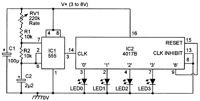
FIGURE 12. Four-LED intermittent moving dot display with 50% blank period.
Figure 13 shows a rather unusual and very attractive four-LED five-step sequencer in which all four LEDs are initially on but then turn off one at a time until eventually (in the fifth step) all four LEDs are off; the sequencing details are given in the table in Figure 13. Note in this circuit that the LEDs are effectively wired in series and that the basic circuit cannot be used to drive more than four LEDs.
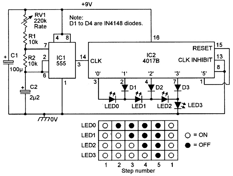
FIGURE 13. Circuit and performance table of a four-LED five-step sequential turn-off display.
Figure 14 shows another unusual and attractive LED display. In this case, the 4017B runs through a 10-step sequence, with LED1 on for steps 0 to 3, LED2 on for steps 4 to 6, LED3 on for steps 7 and 8, and LED4 on for step 9. The consequence of this action is that the visual display seems to accelerate from LED1 to LED4, rather than sweeping smoothly from one LED to the next. The acceleration action repeats in each switching cycle, and the cycles repeat ad infinitum.
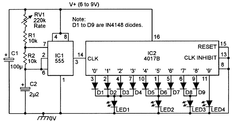
FIGURE 14. Four-LED continuous accelerator display in which the pattern seems to accelerate from left to right.
Finally, Figure 15 shows the circuit of a four-bank five-step 20-LED chaser that can be used as the basis of a variety of attractive LED displays. Note that a bank of four LEDs are wired in series in each of the five used outputs of the IC, so four LEDs are illuminated at any given time. Roughly 2V are dropped across each ON LED, giving a total drop of 8V across each ON bank, and the circuit’s supply voltage must thus be greater than this value for the circuit to operate. A greater number of LEDs can be used in each bank if the supply voltage value is suitably increased.
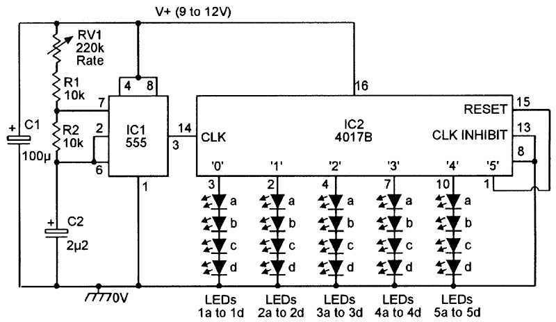
FIGURE 15. This four-bank five-step 20-LED chaser must be used with supply voltages of at least 9V.
One of the most attractive and popular LED sequencer displays is the ‘light-rope’ type, and Figure 16 shows the basic method of constructing a five-strand 20-LED light-rope display that can be driven by the Figure 15 chaser circuit.
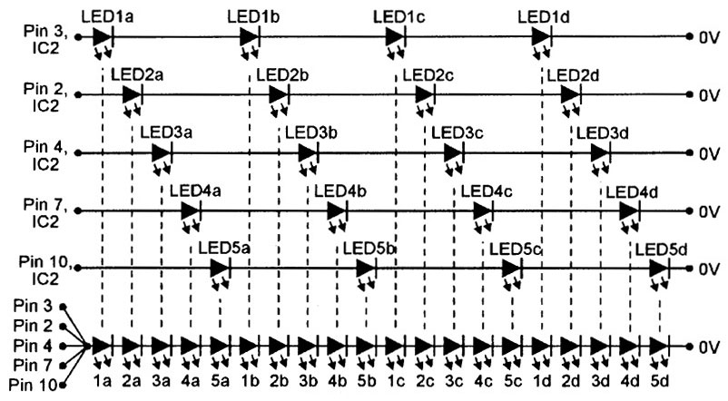
FIGURE 16. Basic method of constructing a five-strand 20-LED light-rope display for use with the Figure 15 circuit.
Here, each group of four series-connected ‘step’ output LEDs of the Figure 15 chaser circuit forms one ‘strand’ of the light rope. There are five strands, and each one must be color-coded to enable it to be connected to the correct output pin of the 4017B IC. In each strand, the four LEDs are evenly spaced apart, but are offset relative to the other four strands, so that there is an equal spacing between all 20 LEDs when the five strands are wrapped together (as shown at the bottom of Figure 16) to form the complete light-rope, which is usually threaded through a length of protective clear plastic tubing.
If a light-rope of this type uses a fixed spacing of (say) five inches between its LEDs, it will have a total length (allowing for a few unused inches at each end) of about eight feet. When the display is active, four evenly spaced ripples of light seem to run continuously along the length of the light-rope, which is driven directly from the output of the Figure 15 chaser circuit.
DISPLAY MULTIPLEXING
The basic action of the Figure 14 four-LED ‘accelerator’ circuit is such that the light display seems to repeatedly accelerate from left to right, taking a total of 10 clock cycles to complete each sequence. Figure 17 shows how the circuit can be modified to give an intermittent display in which the visual acceleration action occurs for 10 clock cycles, but all LEDs then blank for the next 20 cycles, after which the action repeats. The circuit action is as follows.
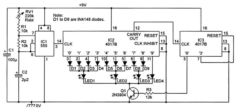
FIGURE 17. Four-LED intermittent accelerator display in which acceleration occurs for 10 clock steps in every 30.
The 4017B has a CARRY OUT terminal on pin 2. When the IC is used in the normal divide-by-10 mode, this CARRY OUT terminal produces one output cycle each time the IC completes a decade count. In Figure 17, this signal is used to clock a second 4017B (IC3), which is wired in the divide-by-3 mode with its ‘0’ output fed to the base of gating transistor Q1. Consequently, during the first 10 clock cycles of a sequence, the ‘0’ output of IC3 is high and Q1 is biased on, so IC2 acts in the basic manner already described for Figure 14, with its LEDs turning on sequentially and passing current to ground via Q1. After the 10th clock pulse, however, the ‘0’ output of IC3 goes low and turns Q1 off, so the LEDs no longer illuminate even though IC2 continues to sequence. Eventually, after the 30th clock pulse, the ‘0’ output of IC3 again goes high and turns Q1 on, enabling the display action to repeat again, and so on.
The Figure 17 circuit is a simple example of display multiplexing, in which IC3 and Q1 are used to selectively enable or disable a bank of LEDs.
To conclude this article, Figure 18 shows another example of a display multiplexing circuit. In this case, the display consists of three lines of six intermittently-sequenced LEDs, and these lines are sequentially enabled via IC3 and individual gating transistors, with only one line enabled at any one time.
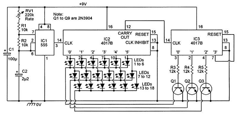
FIGURE 18. Multiplexed six-LED x three-line moving-dot display. The dot moves intermittently along the lines.
Note that the basic Figure 18 circuit can easily be expanded to control up to 10 sequentially-activated lines, which can each have up to 10 LED-driving outputs. The expanded circuit can thus be used as a chaser/sequencer with up to 100 LED-driving outputs. NV