LED ‘GRAPH’ DISPLAYS
One of the most popular types of multi-LED indicator circuits is the so called analog-value indicator or ‘graph’ display, which is designed to drive a chain of linearly-spaced LEDs in such a way that the length of chain that is illuminated is proportional to the analog value of a voltage applied to the input of the LED-driver circuit, e.g., so that the circuit acts like an analog voltmeter.
Practical graph circuits may be designed to generate either a bar-graph or a dot-graph display. Figure 1 illustrates the bar-graph principle, and shows a line of 10 LEDs used to represent a linear-scale 0-10V meter that is indicating (a) 7V or (b) 4V; the input voltage value is indicated by the total number of LEDs that are illuminated.
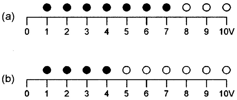
FIGURE 1. Bar-graph indication of (a) 7V and (b) 4V on a 10V 10-LED scale.
Figure 2 shows the same meter operating in the dot-graph mode; the input voltage value is indicated by the relative position of a single illuminated LED. In reality, the ‘0’ position is often indicated on these scales by a separate LED that is permanently active whenever the display is in use.
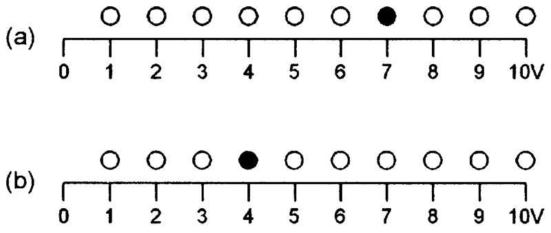
FIGURE 2. Dot-graph indication of (a) 7V and (b) 4V on a 10V 10-LED scale.
A number of special ICs are available for operating general-purpose LED analog-value display systems. For many years, the best known ICs of this type were the U237 (etc.) family from AEG, the UAA170 (etc.) family from Siemens, and the LM3914 (etc.) family from National Semiconductors. However, the first two of these families have now ceased production, and only the LM3914 family remains. The LM3914 family are popular and versatile ICs that can each directly drive up to 10 LEDs (but can easily be cascaded to drive larger numbers of LEDs) and can drive them in either bar or dot mode.
IC-driven bar-graph displays make inexpensive and, in some ways, superior alternatives to analog-indicating moving-coil meters. They are immune to ‘sticking’ problems, are fast acting, and are unaffected by vibration or by physical attitude.
Their scales can easily be given any desired shape. In a given display, individual LED colors can be mixed to emphasize particular sections of the display, and ‘over-range’ detectors can easily be activated from the driver ICs and used to sound an alarm and/or flash the entire display under the over-range condition.
LED ‘graph’ displays have better linearity than conventional moving-coil meters; typical linear accuracy being 0.5%. The scale’s resolution depends on the number of LEDs used; a 10-LED display gives adequate resolution for many practical purposes. A wide variety of multi-LED LM3914-based graph display circuits are shown in this article.
LM3914-FAMILY BASICS
The LM3914 family of dot/bar-graph driver ICs are manufactured by National Semiconductors. They are moderately complex but highly versatile devices, housed in 18-pin DIL packages and each capable of directly driving up to 10 LEDs in either the dot or the bar mode.
The family comprises three devices, these being the LM3914, the LM3915, and the LM3916; they all use the same basic internal circuitry (see Figure 3), but differ in the style of scaling of the LED-driving output circuitry, as shown in Figure 4.
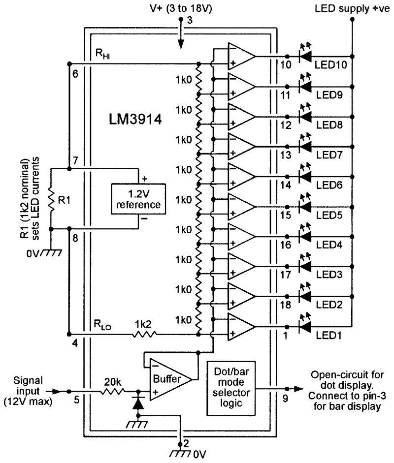
FIGURE 3. Internal circuit of the LM3914, with connections for making a 10-LED 0-1.2V linear meter with dot- or bar-graph display.
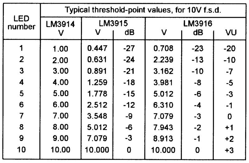
FIGURE 4. Threshold-point values of the LM3914/15/16 range of ICs when designed to drive 10 LEDs at a full-scale sensitivity of 10V.
Thus, the LM3914 is a linearly-scaled unit, specifically intended for use in LED voltmeter applications in which the number of illuminated LEDs gives a direct indication of the value of an input voltage (or of some parameter that is represented by a proportional voltage). The LM3915, on the other hand, has a log-scaled output designed to span -27 dB to 0 dB in 10 -3 dB steps, and is specifically designed for use in power-indicating applications, etc. Finally, the LM3916 has a semi-log scale that spans 23 dB, and is specifically designed for use in VU meter applications.
All three devices of the LM3914 family use the same basic internal circuitry, and Figure 3 shows the specific internal circuit of the linear-scaled LM3914, together with the connections for making it act as a simple 10-LED 0-1.2V meter.
The IC contains 10 voltage comparators, each with its non-inverting terminal taken to a specific tap on a floating precision multi-stage potential divider and with all inverting terminals wired in parallel and accessible via input pin 5 and a built-in unity gain buffer amplifier.
The output of each comparator is externally available, and can sink up to 30 mA; the sink currents are internally limited, and can be externally pre-set via a single resistor (R1).
The IC also contains a floating 1.2V reference source between pins 7 and 8. In Figure 3, the reference is shown externally connected to the internal potential divider (pins 4 and 6). Note that pins 8 and 4 are shown grounded so, in this case, the bottom of the divider is at zero volts and the top is at 1.2V. The IC also contains a logic network that can be externally set (via pin 9) to give either a dot or a bar display from the outputs of the 10 comparators. The IC operates as follows.
Assume that the IC logic is set for bar-mode operation, and that the 1.2V reference is applied across the internal 10-stage divider as shown. Thus, 0.12V is applied to the inverting or reference input of the lower comparator, 0.24V to the next, 0.36V to the next, and so on. If a slowly rising input voltage is now applied to pin 5 of the IC, the following sequence of actions takes place.
When the input voltage is zero, the outputs of all 10 comparators are disabled and all LEDs are off. When the input voltage reaches the 0.12V reference value of the first comparator, its output conducts and turns LED1 on. When the input reaches the 0.24V reference value of the second comparator, its output also conducts and turns on LED2 so, at this stage, LEDs 1 and 2 are both on.
As the input voltage is further increased, progressively more and more comparators and LEDs are turned on until eventually, when the input rises to 1.2V, the last comparator and LED10 turn on, at which point all LEDs are on.
A similar kind of action is obtained when the LM3914 logic is set for dot mode operation, except that only one LED is on at any given time; at zero volts no LEDs are on, and at 1.2V and greater only LED10 is on.
SOME FINER DETAILS
In Figure 3, R1 is shown connected between pins 7 and 8 (the output of the 1.2V reference) and determines the ON currents of the LEDs. The ON current of each LED is roughly 10 times the output current of the 1.2V source, which can supply up to 3 mA, and thus enables LED currents of up to 30 mA to be set via R1. If, for example, a total resistance of 1k2 (equal to the paralleled values of R1 and the 10k of the ICs internal potential divider) is placed across pins 7 and 8, the 1.2V source will pass 1 mA and each LED will pass 10 mA in the ON mode.
Note from the above that the IC can pass total currents up to 300 mA when used in the bar mode with all 10 LEDs on. The IC has a maximum power rating of only 660 mW, however, so there is a danger of exceeding this rating when the IC is used in the bar mode. In practice, the IC can be powered from DC supplies in the range of three to 25 volts, and the LEDs can use the same supply as the IC or can be independently powered; this latter option can be used to keep the IC power dissipation at a minimal level.
The internal 10-stage potential divider of the IC is floating, with both ends externally available for maximum versatility, and can be powered from either the internal reference or from an external source or sources. If, for example, the top of the chain is connected to a 10V source, the IC will function as a 0-10V meter if the low end of the chain is grounded, or as a restricted-range 5-10V meter if the low end of the chain is tied to a 5V source.
The only constraint on using the divider is that its voltage must not be greater than 2V less than the ICs supply voltage (which is limited to 25V maximum). The input (pin 5) to the IC is fully protected against overload voltages up to plus or minus 35V.
The internal voltage reference of the IC produces a nominal output of 1.28V (limits are 1.2V to 1.34V), but can be externally programmed to produce effective reference values up to 12V (as shown later).
The IC can be made to give a bar display by wiring pin 9 directly to pin 3 (positive-supply), or — if only one IC is used — can be made to give a dot display by leaving pin 9 open circuit or by pulling it at least 200 mV below the pin 3 voltage value.
If two or more ICs are cascaded to drive 20 or more LEDs in the dot mode, pin 9 must (except in the case of the final IC in the chain) be wired to pin 1 of the following IC, and a 20k resistor must be wired between pin 11 and the LED-powering positive supply rail.
Finally, note that the major difference between the three members of the LM3914 family of ICs lies in the values of resistance used in the internal 10-stage potential divider. In the LM3914, all resistors in the chain have equal values, and thus produce a linear display of 10 equal steps. In the LM3915, the resistors are logarithmically weighted, and thus produce a log display that spans -27 dB to 0 dB in 10 -3 dB steps. In the LM3916, the resistors are weighted in semi-log fashion and produce a display that is specifically suited to VU-meter applications.
Let’s now move on and look at some practical applications of this series of devices, paying particular attention to the linear LM3914 IC.
DOT-MODE VOLTMETERS
Figures 5 to 9 show various ways of using the LM3914 IC to make 10-LED dot-mode voltmeters with a variety of full-scale deflection (FSD) sensitivities. Note in all these circuits that pin 9 is left open-circuit to give dot-mode operation, and that a 10 µF capacitor is wired directly between pins 2 and 3 to enhance circuit stability.
Figure 5 shows the connections for making a variable-range (1.2V to 1000V FSD) voltmeter. The low ends of the internal reference and divider are grounded and their top ends are joined together, so the meter has a basic full-scale sensitivity of 1.2V, but variable ranging is provided by the Rx-R1 potential divider at the input of the circuit. Thus, when Rx is zero, FSD is 1.2V, but when Rx is 90K, the FSD is 12V. Resistor R2 is wired across the internal reference and sets the ON currents of the LEDs at about 10 mA.
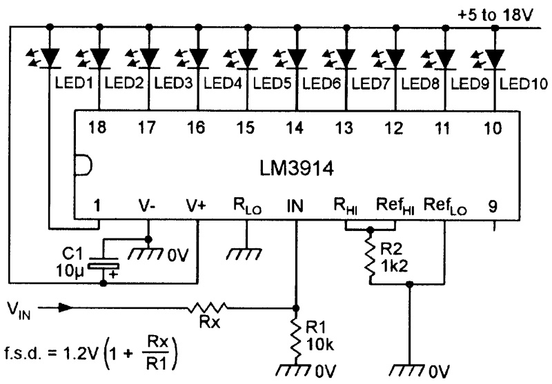
FIGURE 5. 1.2V to 1000V FSD dot-mode voltmeter.
Figure 6 shows how to make a fixed-range 0-10V meter, using an external 10V zener (connected to the top of the internal divider) to provide a reference voltage. The supply voltage to this circuit must be at least two volts greater than the zener reference voltage.
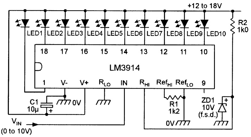
FIGURE 6. 10V FSD meter using an external reference.
Figure 7 shows how the internal reference of the IC can be made to effectively provide a variable voltage, enabling the meter FSD value to be set anywhere in the range 1.2V to 10V. In this case, the 1 mA current (determined by R1) of the floating 1.2V internal reference flows to ground via RV1, and the resulting RV1-voltage raises the reference pins (pins 7 and 8) above zero.
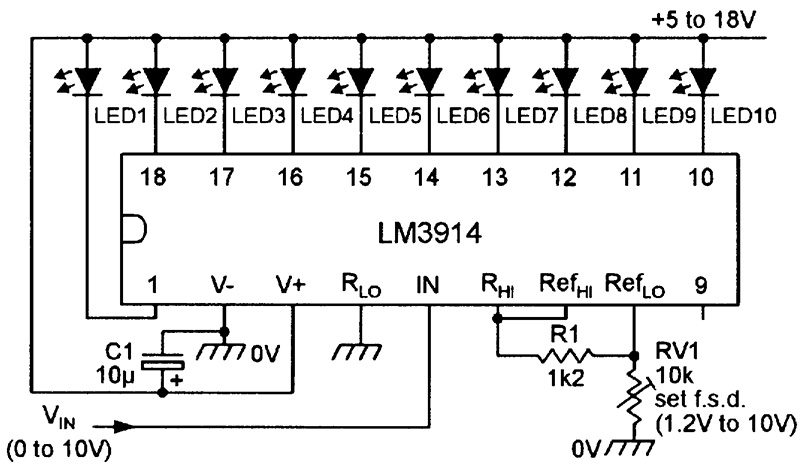
FIGURE 7. An alternative variable-range (1.2V to 10V) dot-mode voltmeter.
If, for example, RV1 is set to 2k4, pin 8 will be at 2.4V and pin 7 at 3.6V. RV1 thus enables the pin 7 voltage (connected to the top of the internal divider) to be varied from 1.2V to about 10V, and thus sets the FSD value of the meter within these values. Note that the circuit’s supply voltage must be at least 2V greater than the desired FSD voltage value.
Figure 8 shows the connections for making an expanded- scale meter that, for example, reads voltages in the range 10 to 15 volts. RV2 sets the LED current at about 12 mA, but also enables a reference value in the range 0-1.2V to be set on the low (pin 4) end of the internal divider. Thus, if RV2 is set to apply 0.8V to pin 4, the basic meter will read voltages in the range 0.8 to 1.2 volts only. By fitting potential divider Rx-RV1 to the input of the circuit, this range can be amplified to (say) 10-15V, or whatever range is desired.
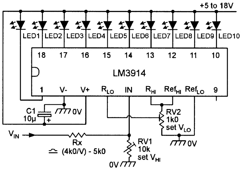
FIGURE 8. Expanded-scale (10V-15V, etc.) dot-mode voltmeter.
Finally, Figure 9 shows an expanded scale dot-mode voltmeter that is specifically designed to indicate the value of a vehicle’s battery (12V nominal). In this case, R2-RV2 are effectively set to give a basic range of 2.4 to 3.6 volts, but the input to the circuit is derived from the positive supply rail via the R1-RV1 potential divider, and the indicated volts reading thus corresponds to a pre-set multiple of the basic range value. As shown in the diagram, red and green LEDs can be used in the display, arranged so that green LEDs illuminate when the voltage is in the ‘safe’ range 12 to 14 volts.
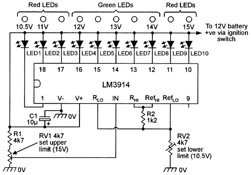
FIGURE 9. Expanded-scale dot-mode vehicle voltmeter.
To calibrate the above circuit, first set the supply to 15 volts and adjust RV1 so that LED 10 just turns on. Reduce the supply to 10V and adjust RV2 so that LED 1 just turns on. Recheck the settings of RV1 and RV2. The calibration is then complete and the unit can be installed in the vehicle by taking the ‘0’ volt lead to chassis and the ‘+12V’ lead to the vehicle’s battery via the ignition switch.
BAR-MODE VOLTMETERS
The dot-mode circuits of Figures 5 to 9 can be made to give bar-mode operation by simply connecting pin 9 to pin 3, rather than to pin 11. When using the bar mode, however, it must be remembered that the IC’s power rating must not be exceeded by allowing excessive output-terminal voltages to be developed when all 10 LEDs are on. LEDs drop roughly 2V when they are conducting, so one way around this problem is to power the LEDs from their own low-voltage (3 to 5V) supply, as shown in Figure 10.
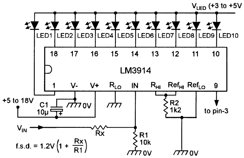
FIGURE 10. Bar-display voltmeter with separate LED supply.
An alternative solution is to power the IC and the LEDs from the same supply, but to wire a current-limiting resistor in series with each LED, as shown in Figure 11, so that the IC’s output terminal saturates when the LEDs are on.
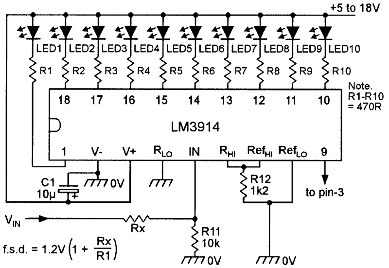
FIGURE 11. Bar-display voltmeter with common LED/IC supply.
Figure 12 shows another way of obtaining a bar display without excessive power dissipation. Here, the LEDs are all wired in series, but with each one connected to an individual output of the IC, and the IC is wired for dot-mode operation.
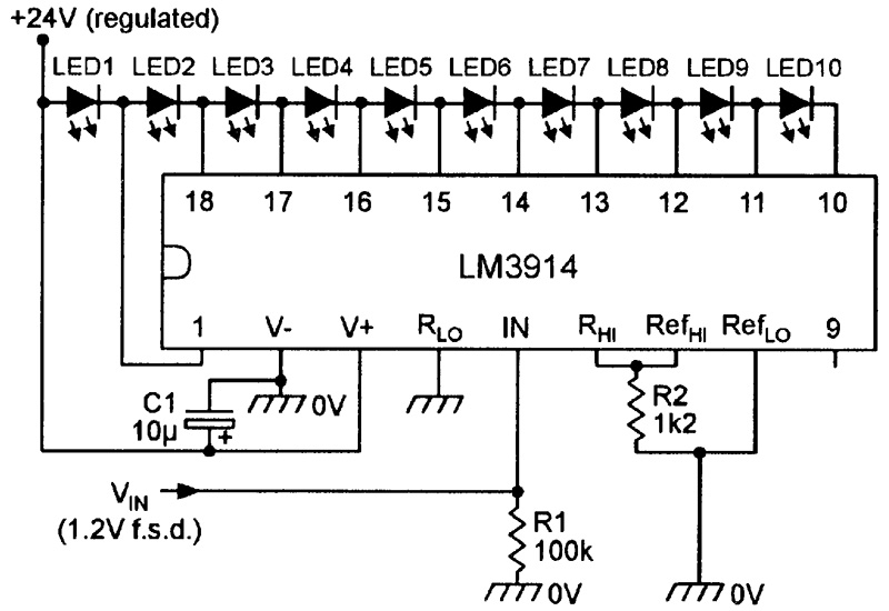
FIGURE 12. Method of obtaining a bar display with dot-mode operation and minimal current consumption.
Thus, when (for example) LED 5 is on, it draws its current via LEDs 1 to 4, so all five LEDs are on and the total LED current equals that of a single LED, and total power dissipation is quite low. The LED supply to this circuit must be greater than the sum of all LED volt-drops when all LEDs are on, but must be within the voltage limits of the IC; a regulated 24V supply is thus needed.
Figure 13 shows a very useful modification which enables the above circuit to be powered from unregulated supplies within the 12 to 18 volt range.
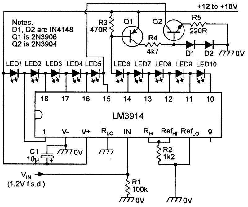
FIGURE 13. Modification of the Figure 12 circuit, for operation from unregulated 12V to 18V supplies.
In this case, the LEDs are split into two chains, and the transistors are used to switch on the lower (LEDs 1 to 5) chain when the upper chain is active; the maximum total LED current equals twice the current of a single LED.
20-LED VOLTMETERS
Figure 14 shows how two LM3914 ICs can be inter-connected to make a 20-LED dot-mode voltmeter.
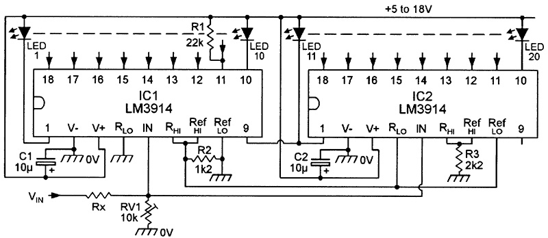
FIGURE 14. Dot-mode 20-LED voltmeter (FSD = 2.4V when Rx = 0).
Here, the input terminals of the two ICs are wired in parallel, but IC1 is configured so that it reads 0 to 1.2 volts, and IC2 is configured so that it reads 1.2 to 2.4 volts. In the latter case, the low end of the IC2 potential divider is coupled to the 1.2V reference of IC1, and the top end of the divider is taken to the top of the 1.2V reference of IC2, which is raised 1.2V above that of IC1.
The 20-LED Figure 14 circuit is wired for dot-mode operation and, in this case, pin 9 of IC1 is wired to pin 1 of IC2, pin 9 of IC2 is open circuit, and a 22K resistor is wired in parallel with LED 9 of IC1.
Figure 15 shows the connections for making a 20-LED bar-mode voltmeter. The connections are similar to those of Figure 14, except that pin 9 is taken to pin 3 on each IC, and a 470R current-limiting resistor is wired in series with each LED to reduce the power dissipation of the ICs.
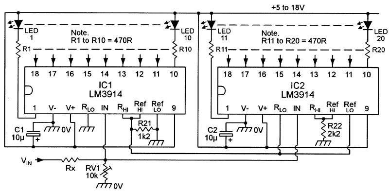
FIGURE 15. Bar-mode 20-LED voltmeter (FSD = 2.4V when Rx = 0).
To conclude this look at LM3914 circuits, Figure 16 shows a simple frequency-to-voltage converter that can be used to convert either of the Figure 14 or 15 circuits into 20-LED tachometers (RPM-meters).

FIGURE 16. Vehicle tacho conversion circuit for use with a 20-LED voltmeter.
This converter should be interposed between the vehicle’s contact-breaker points and the input of the voltmeter circuit. In Figure 16, the C2 value of 22n is the optimum value for a full-scale range of 10,000 RPM on a four-cylinder four-stroke engine. For substantially lower full-scale RPM values, the C2 value may have to be increased — the value may have to be reduced on vehicles with six or more cylinders.
LM3915/LM3916 CIRCUITS
The LM3915 ‘log’ and LM3916 ‘semi-log’ ICs operate in the same basic way as the LM3914, and can in fact be directly used in most of the circuits shown in Figures 5 to 15. In most practical applications, however, these particular ICs are used to indicate the value of an AC input signal, and the simplest way of achieving such a display is to connect the AC signal directly or via an attenuator to the pin 5 input terminal of the IC, as shown in Figure 17. The IC responds only to the positive halves of such input signals, and the number of illuminated LEDs is thus proportional to the instantaneous peak value of the input signal.
The Figure 17 circuit is that of a simple LM3915-based audio power meter that is used to indicate instantaneous output voltage values from an external loudspeaker.
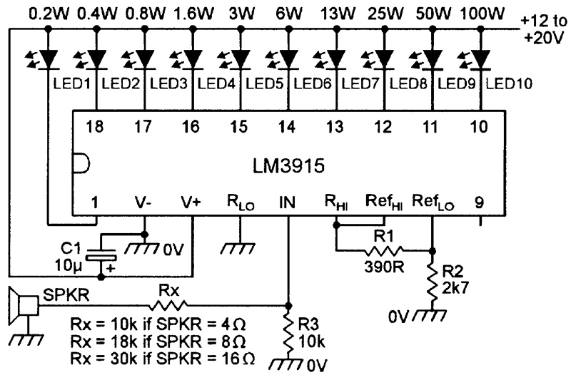
FIGURE 17. Simple speaker-driven audio power meter.
Pin 9 is left open-circuit to give dot-mode operation, and R1 has a value of 390R to give an LED current of about 30 mA, thus giving a clear indication of brief instantaneous voltage levels. The meter gives audio power indication over the range 200 mW to 100W.
Figure 18 shows the basic way of using the LM3916 IC as a VU-meter with a full-scale sensitivity of 10V DC.
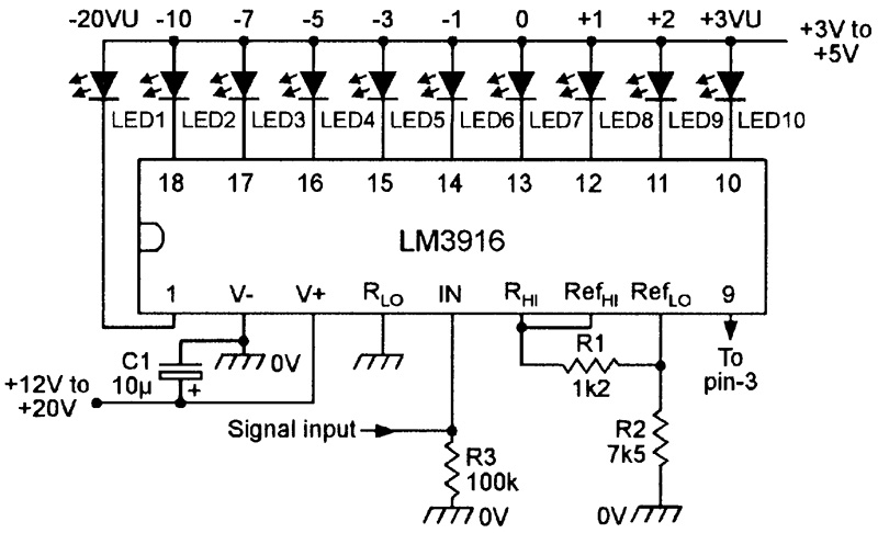
FIGURE 18. Basic bar-mode VU-meter circuit.
The circuit is shown connected for bar-mode operation, using separate supply voltages for the LED display and for the actual IC, and with the component values shown, gives a current drive of 10mA to each active LED.
If preferred, the IC can be used to give dot-mode operation, using a common 12V to 20V supply for the LEDs and the IC, by leaving pin 3 open circuit and changing the R1-R2 values to 390R-2k4, thus giving 30mA of drive to the active LEDs.
Figure 19 shows an alternative way of using the LM3916 as a VU-meter with a bar-type display. In this case, the IC is used in the same way as the basic Figure 12 low-current-consumption circuit, with pin 9 left open circuit so that the IC actually operates in the dot mode, but with the LEDs wired in series across the display-driving pins so that a bar-type display is obtained, with all active LED currents flowing through the currently-active driving pin. With the component values shown, this circuit has a full-scale sensitivity of 10V and provides a LED-drive current of 16mA.

FIGURE 19. This basic VU-meter circuit gives a bar-type display, with a dot-type current drain.
The basic Figures 17 to 19 LM3915 and LM3916 circuits are shown being driven directly from AC signal inputs, and this technique is adequate in many applications.
In cases where the display is required to relate specifically to peak — RMS — or average values of AC input voltage, this can be achieved by interposing a suitable AC-DC converter circuit between the AC signal and the pin 5 input terminal of the LM3915 or LM3916 IC. Many suitable circuits are published in op-amp application manuals and circuit reference books and encyclopedias, etc.
AN OVER-RANGE ALARM-DRIVER CIRCUIT
To conclude this article, Figure 20 shows a simple way of fitting an alarm-driving over-range switch to a bar-type LM3914-series LED-driving indicator circuit.
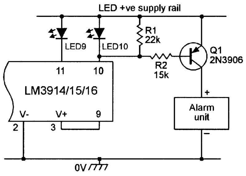
FIGURE 20. An over-range alarm-driver circuit, for use with bar-type displays.
Here, pnp transistor Q1 is wired between the LED positive supply rail and the 0V rail, with its base connected to the IC’s pin 10 (which drives LED10) and with a self-contained alarm unit wired in series with its collector. Normally, LED10, Q1, and the alarm are all off, but if LED10 turns on, it pulls Q1, on via R2 and thus activates the alarm unit, which indicates the ‘over-range’ condition.
In this circuit, the alarm unit may take the form of a piezo siren unit that generates an acoustic alarm sound, or a gated astable switch unit that repeatedly switches the LED brightness between high and low levels under the over-range condition, or may be a combination of both of these units. If desired, the unit can be activated by any one of the display LEDs, in which case, the alarm will activate whenever that or any higher LED is energized. NV