This lightning screen project is based on a design created by Kenneth Strickfaden and used by him in many Hollywood horror and science fiction films (Figure 1). Although it represents a principle of physics centuries old, anyone with a passion for lightning, high voltage phenomena, and electrical history will find this device to be an impressive performer.
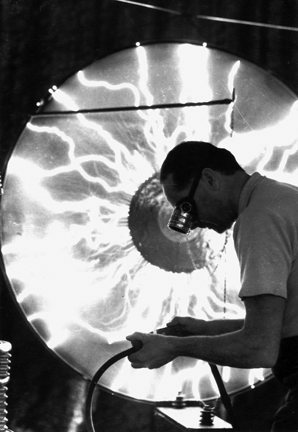
FIGURE 1. Kenneth Strickfaden, special electrical effects wizard of Hollywood’s golden age, is shown operating the lightning screen used in numerous mad scientist movies.
Technically, it consists of a simple two-plate capacitor made from metal discs with a disc of glass as the dielectric. Think of it as a flattened Leyden jar1. The challenging part is not so much electrical as it is in assembling and mounting the components. Refer to Figure 2.
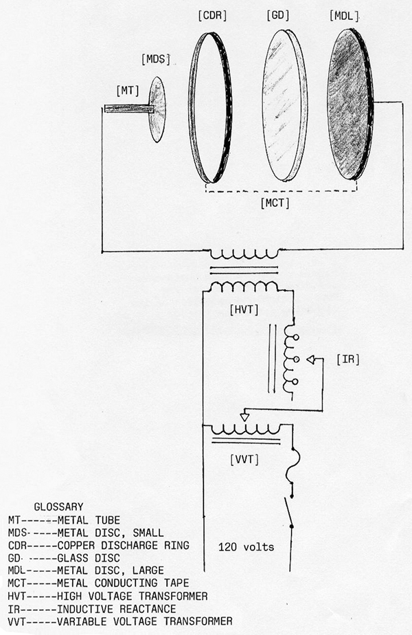
FIGURE 2. The various components and circuit required for the construction and operation of the lightning screen project.
The large metal disc [MDL], glass disc [GD], and copper discharge ring [CDR] are identical in overall diameter. The smaller metal disc [MDS] is not critical but generally one-third the diameter of the large metal disc. The copper discharge ring is formed from one-quarter inch [ID] or larger tubing. Several short lengths of metallic conducting tape [MCT] — strategically placed at equidistant points — create an electrical connection between the large metal disc and the copper discharge ring.
The power source required is dependent upon the overall dimensions of your project. Large systems demand voltages of 30 kV or up. Smaller projects can function at one-half those potentials. This project is powered by an oil-immersed 65 kV x-ray transformer (Figure 3).

FIGURE 3. The 65 kV (oil immersed) x-ray transformer used to power the lightning screen. An inductive reactance is hooked in series to limit the current draw.
However, it will fill the screen with discharges while running at only 50-55% of its rating (Figure 4).
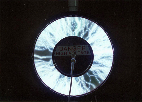
FIGURE 4. The lightning screen’s discharges are not only impressive but very loud.
The final dimensions of your project will be determined by ambition, imagination, craftsmanship skills, and experience with high voltage electricity. Strickfaden’s lightning screens — constructed from discarded and cobbled-up parts — measured approximately 44” across. The screen for this project is a modest 16” [OD] for the large discs with a smaller disc of 8” (Figure 5).

FIGURE 5. The completed lightning screen project.
Now that I have a feel for what my screen can do, I plan to replace the central disc with one having a 5-6” cross-section. This change will result in an increase in the sparking distances and with (no doubt) an accompanying rise in the crackling noise levels.
In assembling the material for this project, I followed Strickfaden’s practice of searching out ready-made items that might be applied to its construction. The supporting framework used here appears to have previously served as a Lazy Susan food tray. The entire assembly is mounted on a mobile cabinet originally designed for audio equipment. Both the Lazy Susan and equipment cabinet were garage sale purchases. Any craftsman skilled in woodworking will have the tools and expertise to design and fashion their own supporting structures. Plus, we’ve seen what marvelous structures can be fashioned from PVC pipe.
The metal rod or tube [MT] extending from the small central disc can either be soldered, welded, or bolted in place. I chose the latter by pressing a threaded shaft coupler into one end of the tube and secured it to the disc with a flathead bolt. It was necessary to form a small depression around the disc’s center hole so the head of the bolt would be in the same plane with its bottom surface. The small central disc is attached to the glass with double-sided tape. It must be mounted at the exact center of the glass disc. An electrical connection was made using a toggle bolt. Once forced into the tube, the toggle stays fixed by friction. It can be easily removed. The entire screen assembly is held in place with simple retainers of non-conducting materials such as plastic, bakelite, wood, etc. (Figure 6).
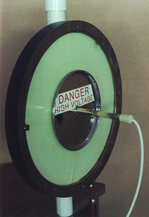
FIGURE 6. A close-up showing comparative sizes of the 16” and 8” discs. Also shown are plastic retaining clips to hold the disc in place. The luminous glow paper behind the glass disc provides the coloration.
I found that discharges emanating from the flat center disc show a tendency for hugging to the surface of the glass. This can create enough heat to eventually crack the glass. By substituting a sturdy metal pie, pizza, or dinner plate, the chance of overheating the glass is greatly reduced. The raised “wings” of the plate position the edge or discharge surfaces above the glass.
Heat resistant (tempered) glass is a better choice of material when it comes to lightning screens. Round tempered glass intended for protecting table surfaces can be obtained from your local big box store (Target, etc.). However, you will have to use it in the size at which it comes as tempered glass cannot be cut down to size. If you are thinking of ordering a custom-sized tempered glass product from a local glass firm, brace yourself when the clerk quotes the price. I used 3/16” common glass for the dielectric. Avoid plain windowpane glass.
Discharges between the center disc and the copper ring are not only impressive but also very loud (ear protectors recommended). By again taking a tip from Strickfaden, the effect is further enhanced when coating the large metal disc with a special luminous paint or paper. The sparks will temporarily leave their signature on the luminous material. A self-stick luminous plastic product can be obtained from Extreme Glow, P.O. Box 3037, Tupelo, MS 38803. The USA phone is 1-888-748-4755. Luminous paints are available from any craft or department store. I did not try paints so I am unable to tell you just how well they work in this situation.
The best way to demonstrate the full effect of the discharges is to operate the screen in total or near-total darkness. Short runs not only create the best after-glow effect but reduce the chance of overheating the glass. Long exposures tend to blur the individual lightning trails on the glow product. Interestingly, there is a simple sketch of a lightning screen on page 180 of Kenneth Strickfaden, Dr. Frankenstein’s Electrician (McFarland, 2005) suggesting the use of a mirror as the dielectric.
To prevent electrical currents from running wild and tripping circuit breakers, an inductive reactance [IR] or choke must be inserted in series with the 120 volt input line of the high voltage transformer [HVT]. I applied a multi-tapped, iron-cored inductor from an old medical machine (Figure 7).
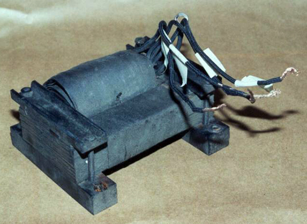
Figure 7: An inductive reactance was placed in series with the 120 volt line to control current draw. This unit was once a component part of an old medical machine.
The tap measuring 20 mH provided the best results. A simple reactance can be made by packing a one-inch by seven-inch plastic or phenolic tube with soft iron (coat hanger) wire cut to 6” lengths and winding it with no less than two layers of #14 or #16 copper conductor. Give each layer a wrapping of tape before continuing winding. Tapping the ends and center turn of the second layer will provide a choice of reactances (Figure 8).
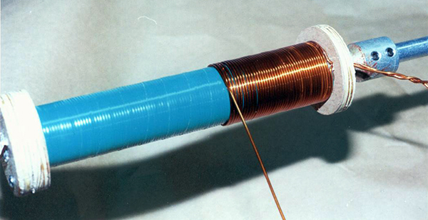
Figure 8: An inductive reactance can be easily constructed using readily available materials as described in this article.
In place of the core of wires, ferrite rings can provide the electrical tinker with a superior inductor core product.
A simpler and less time-consuming method is to connect a 150 watt (or larger) incandescent bulb in series with the transformer input line. Another approach is to insert an electrical heating device (hot plate, toaster, etc.) or similar resistance in the circuit to act as a ballast. My project pulls between 5-7 amperes. No current control is required when screens are powered by current limiting ignition or neon sign transformers.
A piece of equipment not essential to the construction of a lightning screen — but which is highly recommended for its operation — is a variable voltage transformer [VVT] such as a variac, powerstat, etc. The VVT allows full control over operation of the screen and can assist in determining the correct amount of ballast. Too much ballast draws a near-zero current and produces very little sparking. A weak ballast will fill the screen with crackling discharges but at the expense of pulling an excessive current. The VVT allows the operator to find an acceptable balance. Lacking such a control requires energizing the circuit at full voltage. Although this procedure can create startling results, it is a practice I choose to avoid.
Variable transformers featuring both a voltmeter and ammeter are preferred over the single or non-metered models. Unfortunately, purchasing a dual meter VVT can be an expensive proposition. Even a used double-meter model — if one can be found — brings in big money. I surmounted the problem by purchasing a 7.5 ampere meterless VVT at a hamfest for less than $10. I mounted it within an old metal cabinet and added two inexpensive meters along with an inlet, outlet, switch, fuse, and pilot light, for a cost of less than $50. eBay is another good source for finding used variable transformers.
Finally, the lightning screen should not be confused with the safe, silent, plasma-like luminous discs which have become popular sales items at variety stores. On the contrary, the project described herein involves electrical potentials which are unforgiving to those who become careless in its operation. The good news is that the lightning screen is an alternating current capacitor with little — if any — residual charge remaining on the plates once it is shut down. Even so, experimenters must disconnect it from the power line when it becomes necessary to make adjustments or when not in use.
A remarkable person once declared, “No man is an island unto himself.” That statement is certainly true in this endeavor and I gladly acknowledge the valuable input and assistance received from Steve Cole, Mitch Tilbury, and Suzanne Gaeta. NV
Footnotes
- An early form of capacitor invented in 1745 in Leyden [Leiden], The Netherlands.
Parts List
Because of the nature of this project and the spirit in which it is intended, there is no formal parts list. This project can be made from used/collectable parts wherever they may be available, so it is up to the reader to gather the necessary components. Here’s a basic list of some of the items I used in my build. The only item I purchased new was the glass disc.
- 3/16" x 16" diameter glass disc
- 65 kV x-ray transformer
- Inductive reactance, 20 mH
- Large metal disc 16" diameter
- Small metal serving dish 8" D
- Metal tube 4 3/4" x 8"
- 1/4" ID copper tubing
- High voltage wire
- Electrical tape
- Cabinet
- Etc., etc., etc.