An Alternative to Using a Series Shunt
For most of us, measuring DC current means putting an ammeter or low resistance current shunt in the line. In either case, the result is that you intentionally add voltage drop to the line. The problem occurs when you want to check something that draws 20 or 30 amps and your DVM/VOM will handle only 2 or 10 amps. Using a current transformer can help solve this problem, since AC current is easier to handle than DC. A current transformer has an added benefit — the measuring circuit is isolated from the current being measured. There is also a way that you can do it with DC current. This project will provide you with an adapter that can be used with your voltmeter and will measure 100 amps DC.
Theory of Operation
In the simplified schematic (Figure 1), a free-running square-wave oscillator (multivibrator) is built around a voltage comparator and a toroidal inductor. In operation, positive feedback is provided by R2/R3 around the comparator to keep it oscillating. The timing is controlled by the inductor, which is wound on a “square-loop” core. “Square-loop” refers to the shape of the core's hysteresis curve, which has a sharp, well-defined transition when it becomes magnetically saturated. The current through the inductor is small before it saturates, but increases rapidly when the core saturates. The increasing coil current at saturation is sensed by R1 and switches the oscillator's state when the voltage comparator -IN exceeds the +IN.
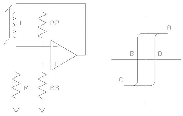
FIGURE 1.
A typical hysteresis curve for the iron core of the oscillator's inductor is also shown in Figure 1. The vertical axis is flux density, usually measured in Gauss. The horizontal axis is magnetizing force, usually measured in Oersteds. Faraday's Law says that the magnetizing force is proportional to the number of turns, multiplied by the current in the turns. It is less common, but perfectly valid, to measure the magnetizing force in amp-turns. During a full cycle of oscillation, the operating point follows the curve from A, where it switches to negative, through B to C, where it switches positive, then back through D to A again. Notice that the area enclosed by the hysteresis loop on the left side is equal to and opposite of the area on the right side. If the oscillator keeps switching at points A and C, the total amp-turns over a full cycle is zero.
Suppose a second “sense” winding is added to the core and suppose also that DC current is flowing in the sense winding. Now, the core is biased in one direction by the added magnetizing current in the sense winding. The oscillator keeps switching at points A and C, so there must be a negative DC current in the main winding to keep the total at zero over a full cycle. This is exactly what happens. The oscillator timing shifts to produce a net DC current in the main winding, which cancels the effect of the DC current in the sense winding.
Remember, it is the product of current multiplied by the number of turns that is balanced. A small current in a large number of turns can be used to cancel a large current in a small number of turns. All of the current in the main winding also flows through R1, so measuring the average DC voltage across R1 tells us the average DC current in the main winding. If we know the number of turns in both windings, we can find the DC current in the sense winding.
As an example, imagine that a wire carrying 100 amps DC is put through the center of the toroid. This forms a one-turn sense winding. The added magnetizing force is 100 amps through one turn, which equals 100 amp-turns. Suppose the main winding has 200 turns. To cancel 100 amp-turns in the sense winding, the DC current in the main winding must be (100 amp-turns)/(200 turns) = .5 amp DC (in addition to the AC oscillator current). If R1 is 2 Ω, .5 amp produces a 1.0-volt average. The scale factor is 100 amps per volt; i.e., there is 1.0 VDC across R1 with 100 amps DC in a one-turn sense winding. Figure 2 shows how this is accomplished in an actual operating circuit.
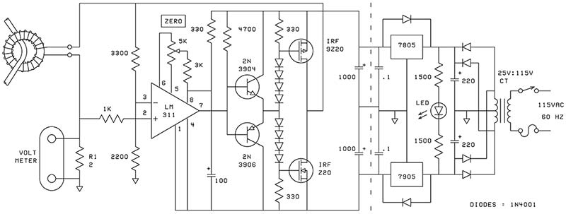
FIGURE 2.
Design Details
The simple comparator detailed in the section above has been implemented using an LM311 integrated circuit, followed by an inverting buffer to supply the coil with current. Since the buffer inverts the signal, the +IN and -IN terminals of the comparator are swapped. The buffer consists of complimentary emitter-followers that drive complementary power MOSFETs in an inverting configuration. The emitter-followers present a high impedance to the comparator, but source enough current to rapidly charge the gate capacitance of the powerFETs. A string of four series diodes offsets the voltage to the gate of each powerFET so that the powerFETs can't turn on at the same time (which would put a short across the power supply).
The power supply provides ±5 V to operate the circuit. Three-terminal voltage regulators are used, which have built-in current and thermal protection, in case of a fault. When the coil core saturates, the current drawn suddenly increases, so large electrolytic capacitors are used on the ±5 V lines to stabilize the voltage during the current spikes. With large capacitors on the regulator outputs, a protection diode is connected across each regulator to keep reverse current out of the chip when the AC power is turned off.
A value of 1.0 volt was selected to represent 100 amperes, since it makes the meter reading easy to interpret. The feedback resistors, R2/R3, are selected so that the comparator trip voltage is ±2 V. This was arbitrarily picked, being twice the maximum 1.0-volt average DC voltage expected across R1. It is well within the common-mode range of the comparator, but much larger than the worst-case input offset voltage of the comparator. A network is included with a potentiometer which allows compensation of the comparator offset voltage; it is labeled “ZERO” on the schematic, since it is used to make the meter read zero, with no current being measured.
Since R1 is 2 Ω, the current at the trip voltage is 1 amp. This current is well within the rating of the powerFETs, won't put a strain on the power supply, and doesn't require heavy wire on the coil. At full scale, with 100 amps in a one-turn sense winding, there will be .5 amp in the main winding, so use a power transformer with at least a .5 amp rating.
Building the Adapter
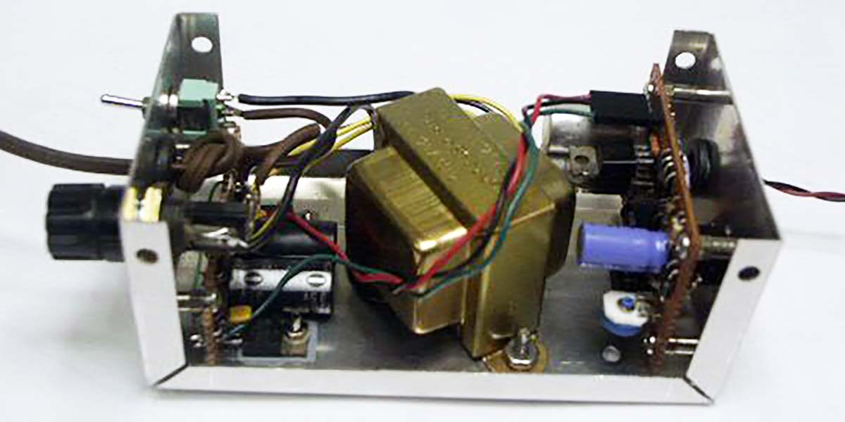
I built my adapter (Figure 3) by mounting the components on perfboard and soldering the connections on the back, using the component leads and/or bus wire. As seen in Figure 3, the adapter was built in a 5.25 x 3 x 2.125 inch aluminum box (RadioShack p/n 270-238). The power transformer (RadioShack p/n 273-1366) is mounted in the center of the box. This leaves the ends for mounting two perfboards on 1/2-inch spacers.
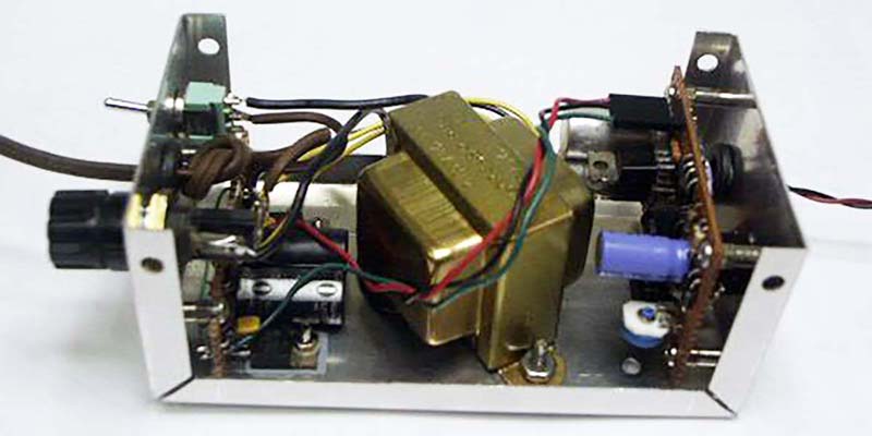
FIGURE 3.
The oscillator section is on the right side of Figure 3. The “ZERO” adjust pot stands up on the board in the lower corner. There is a small hole drilled in the box to allow adjustment of the pot. Leads to the external meter exit to the right through a rubber grommet. An 1/8-inch stereo phone jack (RadioShack p/n 274-249) is mounted on the wall behind the oscillator. Its terminals are bent over to avoid touching anything on the board.
The rectifier/regulator section is at the left side. The voltage regulators are in TO-220 packages, attached to the box for heatsinking. The +5 V regulator has its metal tab grounded, so it's screwed directly to the box. The -5 V regulator's metal tab is not at ground, so insulating hardware is used between the regulator and the box. A T1 size LED is used as a power indicator. It is mounted on the perfboard, but its body sticks partially through an 1/8-inch hole in the box when the perfboard is screwed in place.
The heart of the design is the toroid coil. Recall that well-defined trip points on the hysteresis curve are crucial to good performance. This means a core with high permeability and good “squareness” is preferred, so the impedance change from unsaturated to saturated is large and well-defined. Tape-wound toroids and high-permeability ferrite toroids are obvious choices. Both types will work.
FIGURE 4.
Figure 4 shows some different coil designs. The left coil has a 1-inch, tape-wound core (Magnetics p/n 51061-1A). The other three have 5,000 permeability ferrite cores. The large coil on the right has a 3.375-inch core. This is about the biggest ferrite core available; look for these at hamfests, where they are intended for use in high-power antenna baluns. Each of the two coils in the center has a .87-inch ferrite core. One uses MMG/Krystinel K82 material and the other uses Philips/Ferroxcube 3E2A material. I expect, but haven't verified, that almost any toroid of 5000-permeability ferrite material would work, as well. Results were just as good with a lower permeability material, such as 2,700; I experimented with Philips/Ferroxcube 3C8 in a .87-inch toroid. The coil shown at the bottom center of Figure 4 was made with a one-turn sense winding of 10 AWG connected to big lugs for those cases where you want to connect to a wire that already has big lugs, but won't fit through the small hole in the toroid.
The main winding of each coil was terminated with an eighth-inch stereo phone plug. This allows different ones to be easily attached to the adapter. The coil winding is connected to the “tip” and “ring” terminals, since neither end of the coil is grounded. The grounded “sleeve” terminal is left unconnected.
Calibrating the Adapter
The number of turns on the coil and the value of R1 are directly linked. For example, if the resistance of R1 is 1% high, you compensate by increasing the number of turns on the coil by 1%. Once the adapter is built, wind the coil, but leave enough extra wire to be able to add several more turns, if needed.
For calibration, you need an accurate DC source in the range of 20 to 50 amp-turns. Wind a sense coil on the toroid, using hook-up wire that fits the amount of current you have to calibrate with. For example, 1 amp in 20 turns or 2 amps in 10 turns both give the same 20 amp-turns bias to the coil's core. With 20 amp-turns in the sense winding, the external voltmeter across R1 should read 200 mV. If the voltage is 1% too low, reduce the number of turns on the main winding by 1%. Add turns to the main winding if the external voltmeter reading is too high. Each turn added or removed affects the reading by about 0.5%, so you should be able to calibrate the readings within 0.5%.
Figure 5 shows a plot of data from one of the coils. It shows good linearity over the entire range. Once the turns are adjusted during calibration, many different cores can be used with the same adapter.
FIGURE 5.
A note of caution: when you use sense windings with more than a few turns, the coupling of the sense winding to the main winding can cause ringing. This can make the oscillator have multiple transition bursts at one switching point and ruin the calibration. Whenever you use sense windings with many turns, add a second external coil in series with the sense winding to suppress the ringing. A good choice for the external coil is a winding with the same number of turns as the sense winding, but on a separate core. You can check for this waveform with a scope at the voltmeter terminals.
Using the Adapter
Using the adapter is straightforword; you put the wire carrying the DC current to be measured through the center hole of the toroid and read the value on an external voltmeter. There are, however, things you should be aware of.
There is a large AC component on the signal to the external voltmeter. Not all digital voltmeters do an equal job of ignoring this AC component. If you have problems getting a steady reading, try adding a low-pass filter between the adapter and the voltmeter; a 33K series resistor and a 0.1 µF capacitor across the DVM input should clear it up.
In Figure 4, the largest coil causes the oscillator to have a free-running frequency of close to 60 Hz. The beat note between the oscillator and the AC power line frequency made the DVM reading wander until I added the filter. With the other, smaller coils, the oscillator frequency is 400 to 500 Hz and wasn't a problem.
The voltage regulators can dissipate several watts when measuring larger currents, so expect the box to get warm. The box acts as a heatsink for the regulators.
Be aware that the oscillator in the adapter is producing a signal that is being coupled to the current being measured. If the gear you are testing is sensitive to a signal in the low audio range, you may find the adapter's signal getting into your external circuit.
Part Availability and Substitutions
Most of the parts used in this project are commonly available. The most notable exception is the ferrite cores for the sensor coils. You might try p/n FT87-75 from Surplus Sales of Nebraska (www.surplussales.com).
Power MOSFETs are becoming more available, but there still isn’t much variety at many part suppliers, especially for P-Channel devices. Most power MOSFETs will handle the low voltage of this application, so look for parts with ID values from 5 to 20 amps, Rds from .1 to .5 Ω, and Cin less than 2,000 pF. In a pinch, use NTE2373 for the P-channel and a NTE66 for the N-channel MOSFETs.
Resistor R1 is 2 Ω, can dissipate a .5 watt average at full scale, and must handle a peak of 2 watts twice during each cycle of oscillation. A 1-watt device is a good choice here. Five 1/4-watt, 10 Ω resistors in parallel will also work fine. NV
About the Author
Douglas Glenn is an Electronic Engineer and an Advanced Class Amateur Radio Operator, K3ZMG. This project resulted from the need to measure the current drain of an amateur radio transmitter.
PARTS LIST
| Semiconductors |
|
| Transistors |
2N3904, 2N3906 |
| Integrated circuit |
LM311N voltage comparator |
| Voltage regulators |
LM7805 (+5 V), LM7905 (-5 V), TO-220 case |
| Power MOSFET |
IRF9Z20 (P-channel), IRFZ20 (N-channel) |
| Diode |
1N4001 (qty. 14) |
| LED |
Red, T-1 (3 mm) |
| Passives |
|
| 1/4W, 5% resistors |
330 Ω (qty. 3), 1.5K (qty. 2), 2.2K, 3K, 3.3K |
| 1 W, 5% resistor |
2 Ω |
| Trimpot |
5K |
| Ceramic capacitor |
0.1 µF, 50 V (qty. 2) |
| Electrolytic capacitors |
100 µF, 16 V (qty. 2), 220 µF, 25 V (qty. 2),1,000 µF, 10 V |
| Inductors |
|
| Power transformer |
20 V: 25.2 VCT, .45 A (RadioShack #273-1366) |
| Ferrite core |
FT82-75 (Ocean State Electronics) or FT87-75 (Surplus Sales of Nebraska) |
| Miscellaneous |
|
|
| 0.100” spacing perfboard, 5.25 x 3 x 2.125 metal enclosure (RadioShack 270-238), rubber grommets, fuse (5 x 20 mm, 1 amp) and fuse holder, toggle switch, banana plugs, 1/8-inch stereo phone plugs (and jack), 8-pin DIP socket for LM311N, TO-220 mounting insulator kit, 26 AWG magnet wire, 24 AWG bus wire, 24 AWG hook-up wire, PC board standoffs (1/2-inch long), line cord. |