For the past several years, I’ve been investigating various sources of alternative energy for home use and in my ham radio shack. Some solar panels are in place for charging batteries and I’m producing a quantity of hot water from some old homemade copper collectors, but I started itching for yet another source of green power. I discovered that there is a large undercurrent of experimenters working with small steam powered engines directly coupled to efficient generators capable of producing meaningful power. I decided to see what this was all about. We’re not talking about those massive multi-ton Industrial Revolution engines here. There are many modern 1–10 HP engines available that are realistic for domestic power generation … but where to start?
The Concept
I had just replaced my old gasoline powered weed-eater with a new propane powered four-stroke, and decided to develop an air/steam powered engine from the old remains. However, I refused to completely regress to the old days of mechanical linkages and leaking valves, so I determined that my 21st century engine would have to be computer controlled.
What follows is my effort to convert a conventional two-cycle engine into one that is powered externally by compressed air for testing, then ultimately steam produced by a small, safe “monotube” boiler (see the sidebar at the end).
This engine is completely controlled by a PIC18F2525 based controller that allows complete control of inlet and exhaust timing and duration, with real time RPM and parameter display. The engine piston position is relayed to the processor via Hall-effect magnetic sensors.
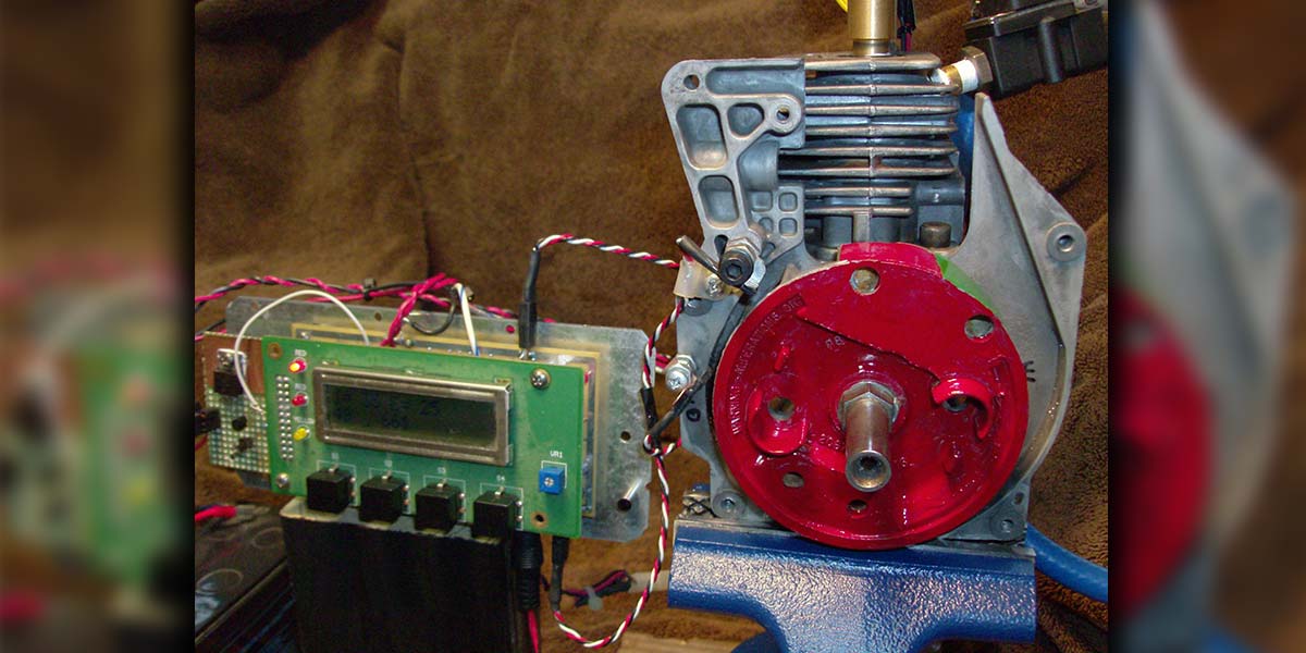
This project is very easily reproduced by any experimenter with average mechanical skills; the controller is an easy breadboard; and — best of all — it’s cheap and green! I found it to be a great platform for learning and applying computer engine control. Figure 1 is the completed engine and controller on the bench.
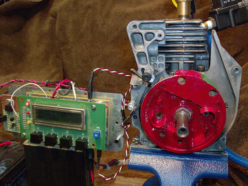
FIGURE 1. Modified engine and controller. The exhaust solenoid is visible in the upper right, and the two Hall sensors are mounted on the frame to the left of the engine flywheel. The red/green zone on the flywheel show the magnets – the demarcation in color is the exact engine Top Dead Center (TDC).
So, let’s get started!
Find An Engine
Any two-cycle engine can be adapted to my controller. I chose the 25 cc weedwacker engine because I had it. However, they can be obtained usually for free by checking your landfill or the trash bin at small engine repair shops. Often people pitch them just because the recoil starter rope broke. Look for one that turns over freely; you won’t need the carb, rope start, or magneto.
Strip it down to the essentials: crankcase and head. Remove the old plastic shroud, exhaust can, recoil starter, and ignition parts. Be sure to remove the rear crankcase “stuffing” plate to expose the crankshaft and connecting rod. If this plate is not removed, the modified engine will exhibit poor performance due to backpressure in the crankcase.
So, How Does This Work?
What we’re building is an “external combustion engine.” The motive power (steam, air) is developed OUTSIDE the engine, not inside as when burning gasoline in a confined cylinder. Our pressurized gas is injected INTO the spark plug hole for a controlled time period, forcing the piston down. At the bottom of the power stroke, the piston uncovers the exhaust port, allowing pressure to escape. Flywheel inertia carries the piston back up for another power cycle.
Our modified engine uses a 12V air solenoid to admit the gas for a specific duration. A second identical solenoid opens on the piston upstroke to release the backpressure that makes the engine difficult to start/run at very low RPM. The timing of the solenoids is based on the engine’s Top Dead Center (TDC) position where the piston is at its uppermost point of travel.
Conveniently, the original spark ignition system functioned by placing two powerful permanent magnets in the flywheel at TDC to induce the high voltage spark current in the magneto coil. We use those magnets to trigger a Hall-effect electronic sensor that indicates the TDC position to the controller — no mechanical interface exists between the engine and controller. The Hall sensor we will employ is an open-collector device used to produce an interrupt to the timing software.
Engine Controller Primer — Timing Is Everything
As mentioned, the controller for the engine is based upon a PIC18F2525 programmed in CCS “C.” Check out the schematic in Figure 2.
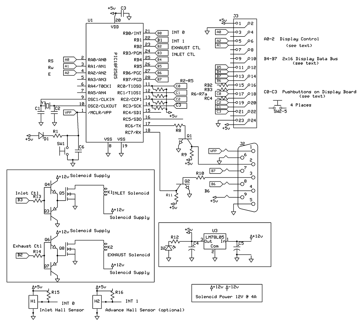
FIGURE 2. Controller schematic diagram. Note the separate +12V power supply for the solenoids. The DB9 connector allows for RS-232 communication (not used here) and in-circuit device programming.
Nothing exotic here, for sure! The entire breadboard requires no more than an evening’s work. I used an existing board/display from another project with modifications for the power FET solenoid drivers. The display uses the upper four bits of port B and three port A bits for its function. Two falling edge external interrupts on port B are triggered by the Hall-effect sensors positioned around the engine flywheel. Multiple 16-bit timers in the PIC are employed to generate the required timing cycles for the engine. Four pushbuttons on port C allow the inlet and exhaust timing to be modified in real time while the engine is running. In Figure 3, the display module is removed, showing the PCB. The inlet MOSFET subassembly is the breadboard on the left; the exhaust driver is in the center of the main board. Note the Hall sensors on the frame of the engine. (Engine TDC is the red/green demarcation line on the flywheel.)
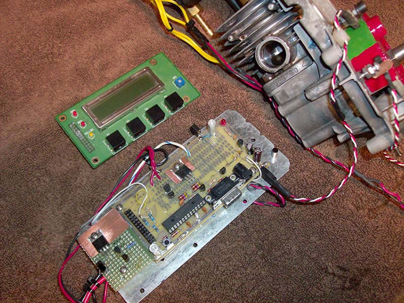
FIGURE 3. Controller details with display board removed. The leftmost breadboard is the INLET logic. The EXHAUST logic is in the center of the breadboard area on the main board. The PIC18F2525 and logic are toward the bottom of the main board. The Hall sensor mounting brackets and adjusting nuts are clearly visible on the engine frame. The engine runs clockwise viewed from the flywheel front. Thus, when the red/green line passes under the upper sensor, the engine firing sequence will commence.
Here’s how it works: When the engine passes TDC, the Hall interrupt triggers a 16-bit timer. Ticking at a 1.6 µS rate, the timer is preloaded with the variable inlet duration time; in my case, about 30 mS for 600 RPM. The inlet solenoid is opened, admitting pressurized gas to power the piston down. Simultaneously, another counter is started to control the opening of the exhaust solenoid based on RPM and inlet timing. The timer 0 (RTCC) clock is started, and on the NEXT TDC its value is used to derive the actual RPM of the engine. The RPM, as well as the inlet/exhaust durations in milliseconds, are displayed.
Finally, the four pushbuttons are checked for activity; two buttons each allow the inlet timing and exhaust position to be modified in real time — up or down — in 0.5 mS increments. Thus, the performance of the engine can be tuned on-the-fly based on the observed RPM and gas inlet pressure. Since there was display space left over, I also show an average RPM value based on 16 engine revolutions for trend analysis.
The running code is split into a “major” and “minor” cycle; each triggered by a TDC interrupt event. I attempted to balance the display and button functions across each cycle to maximize free time in each cycle, allowing for future feature creep.
A second (not required) Hall sensor is positioned at the 20 degree advance point over the flywheel. For the non-motorheads out there, this means the piston is 20 degrees away from the top of the cycle, still going up. The cheap air solenoids I used have considerable latency. After power is applied to the solenoid, it takes several milliseconds (about four) to open, and much longer (about 20) to close when power is removed. These times are factored into the software after much analysis of the solenoids.
Consequently, “firing” the solenoids in advance of the actual desired mechanical effect really increases engine performance. Right now, after starting the engine, the software uses the TDC sensor and transitions to the advance sensor after a user-defined number of revolutions. Again, this feature is a user option.
For interest’s sake, I trigger an LED on the display board to show “idle time” — that is, when the controller is waiting for a TDC interrupt. It is on most of the time. Consider this: At 600 RPM, one revolution takes 100 mS — a lifetime for a PIC running at 20 MHz! There is a ton of processing time for additional features as the code uses only a small fraction of the processor. Most of the time is spent waiting for various interrupts. The source code for this project is on the N&V website and is heavily commented and pretty straightforward. Feel free to modify timing values as you like.
The bipolar drivers for the power MOSFETs are necessary to provide the hard drive required to overcome the high gate capacitance of the devices. As indicated in the schematic, a separate +12V supply at least 4A is needed for the solenoids. Don’t use the logic supply as high switching currents may cause the PIC to reset. The solenoid circuits must not use the logic ground trace. I use a 12V gel cell battery to power the solenoids.
Plumber’s Helper — So Let’s Build One
Okay, you found an old engine and stripped it down. Figure 4 shows an example of suggested plumbing for the solenoids. Use your imagination here — pretty much anything works. The air solenoids I used are cheap plastic body units designed to control the processes in soda vending machines (see the Parts List). They have 1/4” NPT female connections. Adapting 1/4 NPT pipe to the spark plug hole was the most difficult issue with this project. Initially, I broke the ceramic insulator off an old spark plug, and drilled out the center conductor. I brazed a 1/4” NPT short male nipple to the old plug body. Then, I found an old V-8 compression tester in an ancient toolbox, which just happened to have a brass spark plug adaptor to 1/4” NPT threads!
I also tested attaching the pipe nipple to the reamed out spark plug with “ JB Weld “ epoxy. It’s amazing stuff and it was good at 150 psig – much easier! Keep the engine side of the pipe nipples as short as possible, as this is space that must be pressurized and exhausted along with the cylinder as the engine cycles, affecting engine performance. An alternative method is to remove the cylinder from the crankcase and fill the spark plug hole with JB Weld epoxy. After hardening, the epoxy can be drilled and tapped to directly accept the pipe nipple.
The inlet side of the solenoid can be however you want it; use whatever fittings you desire to match your air/steam source. Figure 4 is worth the 1,000 words on that subject.
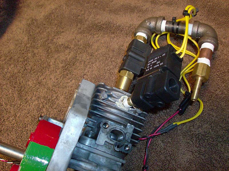
FIGURE 4. Inlet and exhaust solenoid plumbing. The exhaust solenoid is in the foreground – note the 1/8” NPT nipple angled into the upper cylinder wall. The inlet solenoid is directly behind the exhaust device. The brass “spike” allows air/steam to be admitted to the inlet solenoid. With the exception of the exhaust, all plumbing is standard 1/4” NPT hardware store material. Seal all joints with Teflon tape or pipe cement.
There are two ways of plumbing up the exhaust solenoid. I drilled and tapped a 1/8” NPT hole in the side of the cylinder just above the maximum piston travel, and adapted it to the solenoid with a 1/8” to 1/4” bushing. The exit side of the exhaust solenoid is left open to the atmosphere. An alternative method — which I used initially — is to use the spark plug hole for BOTH inlet and exhaust … the short nipple from the plug hole mates to an NPT “tee” fitting. The second hole in the tee mates the exhaust solenoid, and the third to the inlet solenoid. The engine performance is not quite as good with this scheme, due to the inlet and exhaust bucking each for access to the spark plug hole during gas flow transitions.
However, I found that by tuning the engine with the control buttons, a sweet spot could be found based on the gas dynamics and pipe length resonance resulting in big performance increases at specific RPMs. Remember to use Teflon pipe tape or sealant as NPT fittings by their nature leak under any pressure. Use black iron pipe — while those bronze pipes look nice, they are expensive. Pipe nipples and fittings are common at all hardware stores.
The tiny Hall-effect magnetic sensors are mounted to the frame of the engine. The soft aluminum engine was super easy to drill and tap for a 6-32 machine screw. I superglued the sensor to a small copper tab, then bent it 90 degrees. The TDC point of the engine is easily determined by watching the crankpin or piston as you rotate the flywheel. At TDC, the original magneto magnets will probably be at the top of the flywheel. My engine has a small, 1/8” gap between the magnets — the actual TDC position. Position the Hall sensor over that gap, about 1/4” inch from the flywheel. Mark the spot on the frame for your copper bracket, and drill/tap a 6-32 or 4-40 hole (again, epoxy/superglue is fine). I used two extra nuts on the bolt to allow additional freedom in positioning the sensor. TRUST ME – the actual position is not critical as long as you are within a couple degrees of TDC. Also, the Hall sensors are shockingly sensitive against the massive magnets in the flywheel. I was able to reliably test my engine holding the sensor 2.5” away from the flywheel.
Component Selection
Although I mentioned how straightforward this project is, some comments about the circuit and components should be mentioned. If you follow the Parts List suggestions, you can’t go wrong. However, we all like to substitute and scrounge — that’s what this is all about! Anyway, I used an Internet Special surplus display board with built-in switches and LEDs. Any 2x16 LCD can be used as long as it is based on the Hitachi HD44708A style controller. The LEDs and switches can be discrete, as noted in the schematic. I highly recommend the display board indicated in the Parts List. It is a nice package and will directly mate to your logic board using connector J3.
Hall-effect sensors come in different flavors. The ones to use are the “6852” series — under $1 each. They respond to a south-pointing magnet. Some Hall sensors I investigated latch up when energized and require an opposite magnetic field to turn them off — no good here.
Also, when mounting the Hall sensor, the “hot” surface is the side of the package with the numbers. That surface should face the flywheel magnets. The back of the package — while not as sensitive — will respond to a north-seeking magnet.
While looking down at the sensor with the pins down and part numbers facing up, the left pin is ground, the center pin is +5, and the rightmost pin is the open collector output.
Finally, you may have noticed that I “forgot” flyback diode protection on the solenoid coils in the schematic. Well, I originally used them with the result of adding over 15 mS of close time to the solenoid due to the flyback current when the device is shut off. Tough on the timing analysis, for sure.
The N-channel IRF Z30 or equivalent power FETs I used employ internal kickback protection diodes and are designed as solenoid drivers.
Bottom line, if you use the parts I specify, your engine will run with few issues — but don’t be afraid to substitute and experiment within reason! I used small copper tabs as heatsinks for the power FETs — probably not necessary considering the solenoid duty cycle.
Running Up!
I initially mounted the engine in a small bench vise for testing. Connect the Hall sensor(s) to your controller breadboard and a 12V source to the solenoid circuit. If you used my schematic and software as shown, rotating the engine slowly clockwise should produce satisfying clicks of the solenoids as the flywheel passes over the Hall sensor(s). The LEDs will flash as the solenoids fire; after one revolution, the display will indicate RPM and timing parameters. If you manually turn the engine over for a bit, you will observe the actual and average RPM display changing.
Now, connect a compressed air source to the input side of the inlet solenoid. Start with 10 to 20 psig air at most. Manually position the flywheel such that the magnets are about 45 degrees away from TDC. A hard clockwise flip should start the engine at about 400-600 RPM. Fine-tuning of the inlet/exhaust timing will produce dramatic increases in RPM and power. I’m working on a second release of the software that will auto-tune the engine for maximum RPM at a given air/steam pressure. I will post it on the server when available, so stay tuned!
You’ll find the engine will require retuning with differing gas pressure and load. The engine is running in Figure 5.
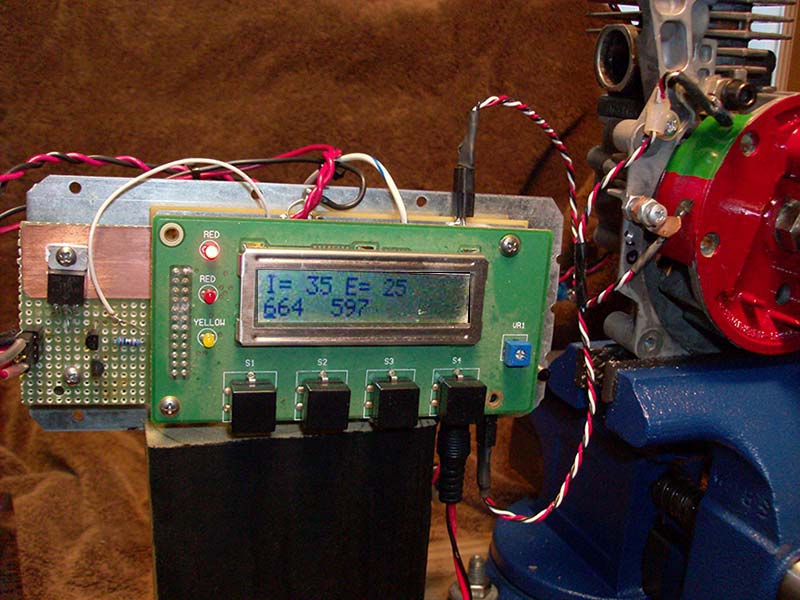
FIGURE 5. Controller and engine in operation. Note inlet and exhaust timing in milliseconds on line 1 of the display, and the real time and average RPM on line 2. The four pushbuttons control gas timing. The leftmost two buttons INCREASE and DECREASE control inlet (power) timing respectively, and the rightmost buttons INCREASE and DECREASE control exhaust timing. The relationship between inlet and exhaust cutoff is controlled by the software. The main exhaust port is the round opening on the left side of the cylinder.
The inlet and exhaust timing in mS is indicated on the top display line, and the actual and average RPM on the second line. The engine is accelerating in this example.
When tuning the engine, start by increasing the duration of the inlet pulse (left button). You will get to a point where the exhaust note becomes noticeably sharper and higher pitched. This indicates that the inlet is still open when the exhaust port on the cylinder is uncovered by the piston, thus wasting power. Decrease the inlet pulse a bit, and watch the RPM increase. The exhaust assist solenoid timing is critical only at higher RPM – above 1,200 RPM or so.
Most of the weedwacker engines out there are about 25 cc in displacement; mine has a 1” bore and a stroke of 1.125”. The inlet duration is set for about 60% of the power stroke, as steam will continue to expand and provide power after timing cutoff. The built-in start timings for a 600 RPM start-up are based on those dimensions, and are obvious in the source comments.
Have fun, and stay green with steam! NV
Why Computer Engine Control
Piston engines produce power based on the force of a gas (burning air/gasoline mix, steam, compressed air, etc.) acting on a piston(s) within a closed cylinder(s). The up/down piston motion is linkage coupled to a crank that produces the more familiar circular motion. Timing and moving the gas in and out of the cylinder usually requires a series of valves, pushrods, and eccentrics (cams) mechanically connected to the crank. The spark that fires the cylinder is also timed by yet more linkages — the end result being the engine usually runs most efficiently within a very narrow RPM/power range. Operation outside that range results in pollution, wasted fuel, and poor performance.
The automobile and small engines we are so wedded to in today’s society would have been legislated into oblivion years ago if not for the introduction of computerized engine control – the “module” controlling every aspect of engine operation. Spark timing, pollution control, air-fuel mixture, and even linkages are now controlled “off engine” based upon RPM, load, temperature, fuel quality, and altitude. The computer allows modification of parameters that used to be fixed by rigid mechanical linkages.
The engine described here is a “modified uniflow single-acting two stroke”. Unlike the four-stroke automobile engine described above, the uniflow engine accepts compressed gas above the piston, and drives it down until an exhaust port milled into the lower cylinder wall is uncovered, allowing used gas to escape. The exhaust does not have to be forced out by an additional piston stroke, thus you have “uniflow” — in the top, out the bottom. Single-acting means the engine only produces power on the down stroke, not when returning. However, the timing of the external power (gas) is based on engine RPM, desired torque, pipe diameter, and solenoid latency — once again, enter computer control! The simple platform described here allows the builder to apply real computer control to an engine and actually observe how tuning a mechanical device can radically improve (or degrade) performance. As with most things, knowledge is power!
When operating with steam, DO NOT be tempted to construct a boiler out of a coffee can or the like and place it on a fire! Compressed steam has massive potential energy and must be treated with total respect. I use a “mono-tube” boiler that consists of a continuous coil of tubing — water in one end, and steam out the other. There is no captive container of steam to explode. Feel free to contact me for details and, as usual, there is a wealth of information on the Web – search for “mono-tube steam boiler.”
PARTS LIST AND RESOURCES
| COMPONENT |
DESCRIPTION |
| All resistors are 1/8 watt film or wire. All capacitors are disc ceramic 15V unless noted. |
| D1 |
1N914 or equiv. diode |
| D2 |
Red LED |
| C1-C2 |
18 pF |
| C3-C4 |
01@15V |
| C5 |
.0 µF@50V |
| H1, H2 Hall |
DN6852-A |
| J2 |
DB9, right angle if used |
| J3 |
24-pin female header (display) |
| K1-K2 |
Process air solenoid, 1/4” NPT |
| R1, R12-R16 |
4.7K |
| R2-R7a |
1K |
| R8, R10 |
10K |
| R9, R11 |
2.7K |
| Q1-Q2, |
|
| Q4, Q6 |
2N2222A transistor or small signal NPN |
| Q3, Q7 |
Small signal PNP transistor |
| Q5, Q8 |
IRF-Z30 or equiv. N-channel power MOSFET |
| Y1 |
Crystal, 20 MHz, HC-49/U 18 pF |
| |
|
|
The LCD front panel set consists of a 2x16 display with HD44780 controller, three indicator LEDs, and four NO pushbuttons. It mates to J3 above. Discrete display, buttons, and LEDs may be used if desired. Available from www.piclist.com/techref/io/lcd/panel1.htm.
Thanks to Peter Nicola N1DYL for designing the PCB. It was fabricated by ExpressPCB using their free design tools.
The PIC code and ExpressPCB file are available in the downloads.
|
Downloads
Computer Controlled Steam Engine Download