In 1990, my wife and I had the great opportunity to visit and live in Russia. We stayed with a family in Kiev located in the Ukraine. The Chernobyl disaster had occurred four years earlier and they were still washing down the streets daily. In those days, it was illegal in Russia for the people to possess a Geiger counter, so they had to rely on local authorities.
Fedor, our host (also a Russian physicist,) was most concerned about his grandchildren and the effects of the radiation. Rumors were still flying after four years, and no one really knew the facts. Milk and produce were their main concern. He asked me if I could provide him with a Geiger counter. When I returned to the states, I decided to put one together and sent it to him. The radiation levels he found were of concern, especially in tree fruit.
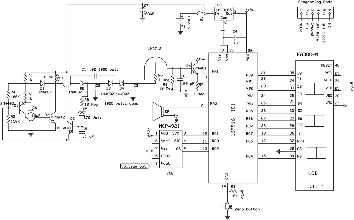
I recently re-examined my schematic of this unit. I added a microprocessor for control and a new display. I recommend an LND 712 Geiger tube which appears to be the gold standard of portable counters. It is capable of measuring alpha, beta, and gamma particles.
If you don’t want to spend a lot of money on a Geiger tube, you can find some on eBay for under $5. (Keep in mind that you may need to adjust the high voltage for the tube. This is discussed further in the sidebar on Hints and Tips at the end.)
This device would be a great project for high school and university students. It is simple to assemble and teaches a number of techniques.
The unit detects and displays levels of radiation, and can detect and display dosage levels as low as one micro-roentgen/hr to many micro-roentgens/hr. It can also detect radon (which emits alpha particles).
This unit has an advantage over other devices because it has an output for recording months of data — showing trends of radiation with a data logger.
Electronics
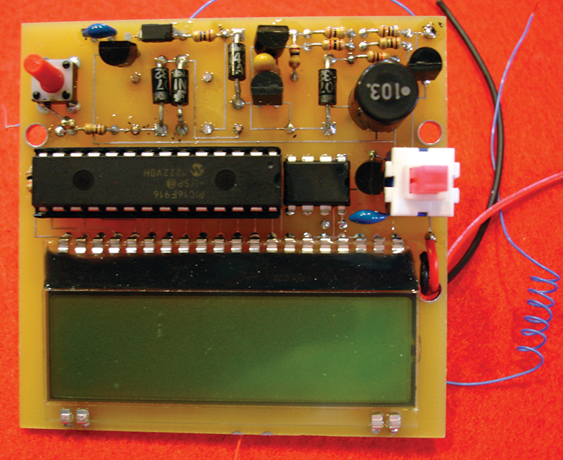
The brain of the counter is a PIC16F916 microprocessor. You will need to program it. (The chip included in the available kit is preprogrammed.)
Geiger tubes require high voltages — often over 500 volts. However, they pull a very small amount of current in micro-amps. The high voltage is generated by Q1 and Q2 and the choke. Q3 reduces the amount of power the unit uses, thus increasing battery life. A combination of high voltage capacitors and diodes increase the voltage as they are in a voltage tripler configuration.
A zener diode controls the voltage to the tripler via feedback to Q1. I used a 270 volt surface-mount zener. In theory, if tripled it should produce 810 volts; in practice, it produces 600. Keep in mind that the circuit generates very little current. Therefore, trying to measure it with a standard DVM will load down the voltage reading. Touching any part of the high voltage circuit will give a startling effect.
The output from the tube (note it comes from the case of the tube) is converted to a suitable voltage using Q4 as an NPN transistor to the microprocessor. The micro has a built-in timer and is capable of counting seconds, minutes, hours, and days. A momentary switch programs the time for collection which is displayed on the LCD.
The number of counts per minute are converted by the digital-to-analog converter (DAC); this voltage is available via the RCA jack.
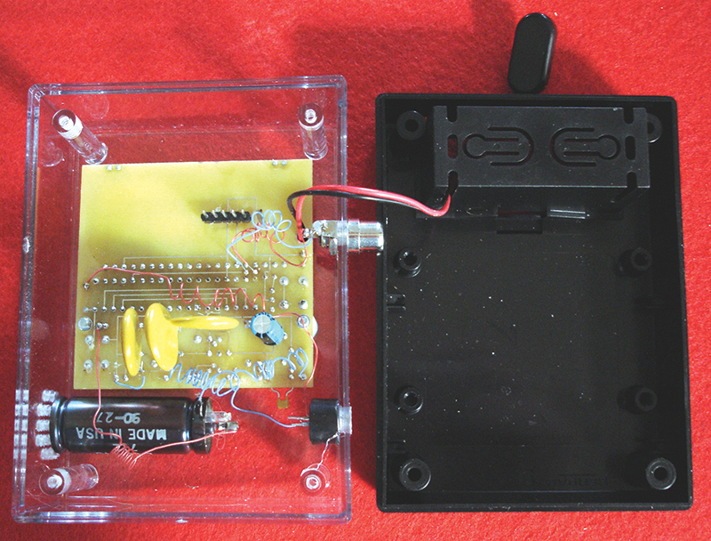
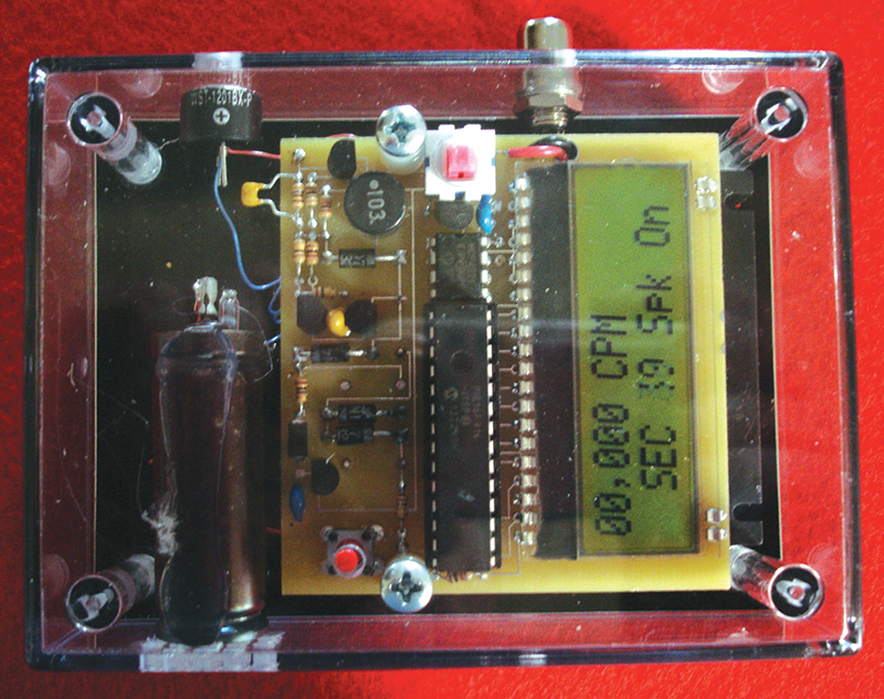
The unit is housed in a Serpac case with a nine volt battery insert.
Building the Unit
The board files from ExpressPCB.com are located in the downloads at the end of the article, along with assembly files for the microprocessor. The microprocessor can be programmed on the board using a PICkit 2 programmer.
Solder IC1 and IC2 to the top of the board noting pin 1 has the square pad; see Figure 1.
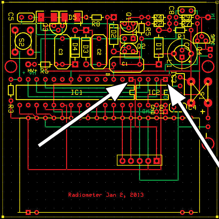
FIGURE 1.
D5 is the surface-mount zener and has an indented line across one end. This is the cathode.
Solder D5 to its pads. You will see another set of pads to the left of D5 with a trace across shorting the pads; refer to Figure 2.
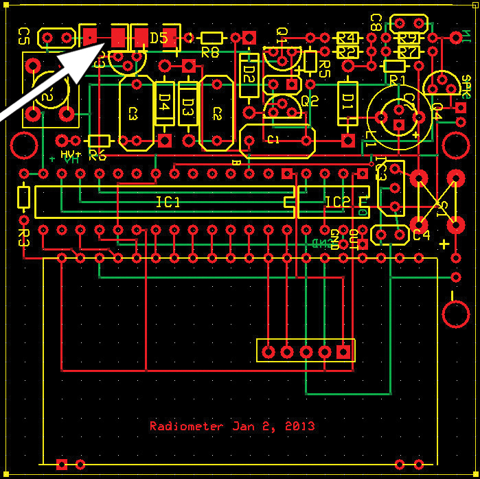
FIGURE 2.
Do NOT solder D5 to these pads; they are for an extra zener if you’re using a Geiger tube other than an LND 712. Solder the remaining diodes, noting their polarity. Solder IC3, paying attention to its flat side so it’s pointing to the switch. Solder in the transistors. Solder C4, C5, C8, and C6, noting polarity and all the resistors. Solder the two switches and the LCD.
Now, turn the board over and place C1, C2, and C3 on the bottom side and solder. C7 also goes on the bottom side. Lift it off the board about 2-3 mms so you can solder L1. Note its polarity and solder; refer to Figure 3.
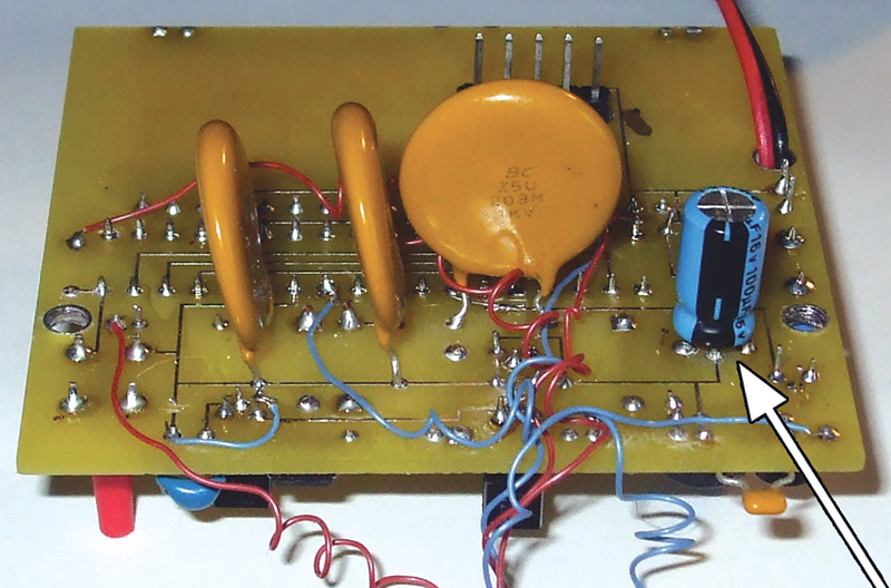
FIGURE 3.
Place L1 on the top of the board and solder.
Chassis
Using the four screws, attach the top and the bottom of the chassis together. The screws will self tap and it will make it easier for final assembly; secure the box for drilling.
Go to the article link and download the template. When you cut out the template, glue it to the top and sides of the box. The battery box should be on the top. Drill the holes as marked and deburr them as necessary. Hot water will remove the templates.
Place the nine volt battery snap inside the chassis (facing the bottom), and run it through the slot on the right side. Run the battery wires through the strain hole of the board and solder the red wire to the + and the black wire to the -. Solder the wires; refer to Figure 4.
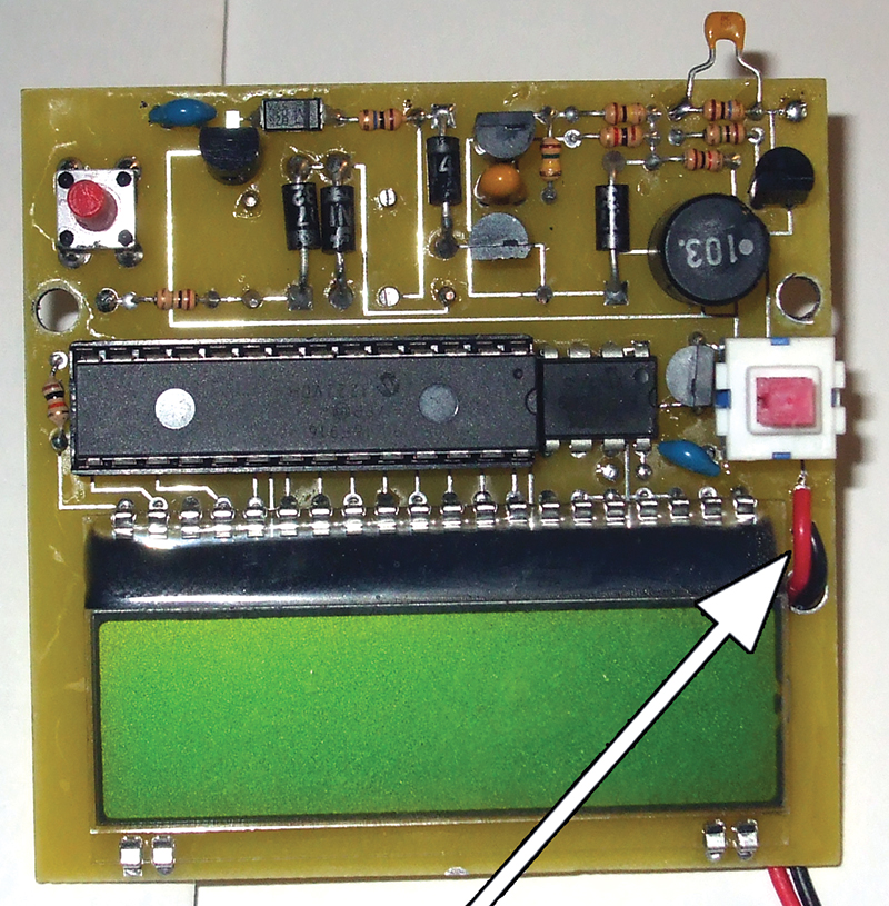
FIGURE 4.
Using two 3/8” standoffs, mount the board to the top chassis using 1/2” 6-32 screws. The holes in the board will self thread.
The end window of the LND 712 is very thin and fragile, and is easy to poke a hole into. (I speak from experience.) Strip a 4” piece of #30 blue wire wrap on the short wire coming from the side of the tube.
Solder a 4” #30 wire wrap red wire to the end clip of the Geiger tube. Place a piece of insulated tubing over the end clip to prevent shock. Coil both the wires.
Mount the Geiger tube next to its hole using a hot glue gun. Looking at the bottom of the board, solder the red wire to the HV+ pad and the blue wire to the IN pad.
Wire wrap a 4” red wire to the + post of the speaker and a 4” blue wire to the other post. Coil the wires. Glue the speaker to the side of the box with hot glue. Solder the blue wire to the round pad and the red wire to the square pad on the ones marked SPK.
Place the RCA jack into its hole. Solder 4” of red and blue wires to the RCA jack. Red goes to the center pin. Solder the red wire to the square pad (pin 8, IC2) and the blue wire to the round pad (pin 7, IC2). Coil the wires using a 1/8” diameter screw driver or 1/8” drill, and coil the wires for easy storage.
Secure the box with the four screws.
Testing the Unit
Snap a nine volt battery into the battery clip. Push the on-off switch. The display should show a readout in CPM (counts per minute) which is the default. As radiation is detected, a click will be heard and the counter will increase. Pushing the mode button will advance the display from rems (the unit of radiation dosage — such as from X-rays — applied to humans) per minute, hours, and days. If the mode button is held down for more than five seconds, it will reset all the counters and registers.
If in micro-rems per minute, the unit will count 60 seconds and then latch the counter showing the count for that particular minute. The unit will still be counting — as demonstrated by the click and the flashing of a † on the display — but it will not display a running count until the next minute. A countdown in seconds will be shown until the results toggle. The same occurs for hours and days. The unit will automatically change from micro-rems to milli-rems as needed.
The unit will sound an alarm for five seconds if the count exceeds a calculated .5 micro-rems in a minute period (30 µR/Hr). To turn off the alarm and beeping, turn the entire unit off and hold the mode button down; then turn the unit on again.
The background count will vary with the area you live in; 12 µR/Hr is about average. I get 20 per hour at my laboratory; this is probably due to the altitude of Carson City. Before 9-11, I took the unit in an airplane and turned it on at 35,000 feet. It will make you wonder why you are flying; it registered 300 µ/R Hr.
Pick up a Coleman lantern mantle and use this to test the unit. It contains thorium that is radioactive and emits alpha particles. The unit draws about 10 mA, and a nine volt battery will last about two days. Use a nine volt DC battery eliminator if recording for days or months.
Making a Radiation Graph
I use two types of devices for making graphs. The first is a Dataq EL-USB-3 which is a voltage data logger that plugs into the USB port of a computer. This device makes the Geiger counter truly portable. It sells for about $75. It measures 0-30 volts, and can be set to record from one second to a 12 hour interval. At one minute intervals, it will record 22 days of data. It is only sensitive to 50 mV which is 41 CPM.
The second device I use is my favorite. It is the Dataq DI-145 which sells for $29. It is a must for any scientist.
Most of us have an older computer sitting around gathering dust that we can utilize with this unit.
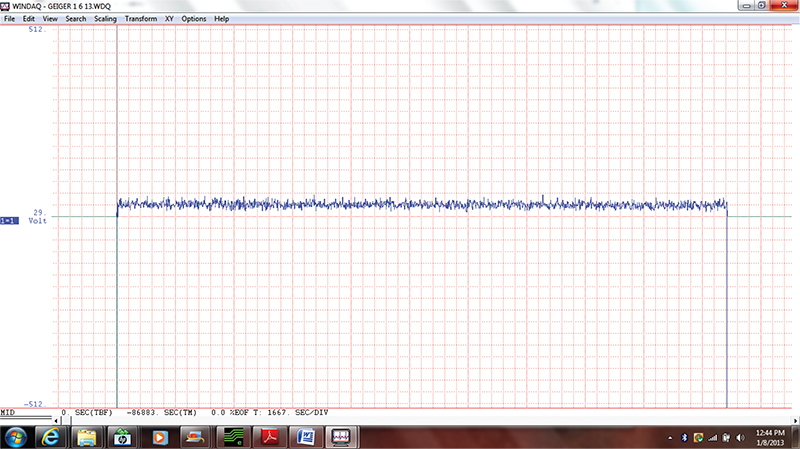
The device will record up to four channels at one time and with Dataq’s free WinDaq’s software, it is a very powerful tool. You can monitor gravity, the tilt of the earth, plus seismic activity, magnetic fluxuations, and radiation all at the same time, so you can observe any correlations.
The software graphs out all on the same sheet. Just plug in either device into the RCA jack. Its sensitivity is .001 volts which is 1 CPM.
What Are We Measuring?
Well, as usual, when entering in the scientific world there is a plethora of terms and units. Fortunately, for our purposes, one roentgen equals approximately one rad, which equals one rem.
A rad (Radiation Absorbed Dose) is the unit for measuring absorbed doses of radiation. The rem (Roentgen Equivalent Man) is the damage that one roentgen causes to humans. The roentgen is the quantity of X-rays or gamma rays.
One roentgen is a lot of radiation and is equivalent to about three to five years of normal exposure. This is why milli-roentgens and micro-roentgens are used. A milli-roentgen is equal to 1/1000 (1 x 10⁻³ roentgens) and a micro-roentgen is equal to 1/1,000,000 (1 x 10⁻⁶ roentgens). The unit we are building measures in micro-roentgens.
Due to a number of factors (type of tube, calibration, and different types of radiation), consider one click or one count 1/105 of a micro-roentgen (1 x 10⁻⁶ roentgens).
There are three main types of ionizing radiation. (Ionizing radiation causes changes in tissues and can cause cancer.)
Alpha particles are positive charges that are very short lived. A sheet of paper can stop them, however, if ingested or inhaled they become very deadly. Radium is a naturally radioactive element. When it emits an alpha particle, it becomes radon — a radioactive gas with a half-life of 3.8 days. Just as there are earth tides, it has been reported that radon tides also vary from day to day.
Beta particles are much smaller than alpha particles and are negatively charged, but can be blocked by a thin sheet of aluminum foil.
Gamma rays are electromagnetic radiation and are stopped by lead, concrete, or steel.
Depending on what you read, we are exposed to about 100–200 milli-roentgens per year. A chest X-ray (low level gamma rays) gives us about 10 milli-roentgens of exposure.
When should you become alarmed? This is difficult to say, however, the EPA forbids radiation exposure above five rems in any one year to radiation workers.
I hope you enjoy building and using this radiation counter. NV
A complete kit to go with this article can be purchased online from the Nuts & Volts Webstore.
PARTS LIST
| QTY |
ITEM |
DESCRIPTION |
PART # |
SOURCE |
| 1 |
B1 |
Heavy Duty 9V Snap Connector |
234K-N |
Digi-Key |
| 1 |
Box |
4.38" x 3.25" x 2.00" |
SR232-CB-ND |
Digi-Key |
| 3 |
C1-C3 |
.02 µf 1,000V |
594-S203M75Z5UN63J0R |
Mouser |
| 2 |
C4, C5 |
.1 µF |
0-FK18X7R1E104K |
Mouser |
| 1 |
C6 |
10 µf |
581-TAP106K010SCS |
Mouser |
| 1 |
C7 |
100 µF 16V |
140-REA101M1CBK0611P |
Mouser |
| 1 |
C8 |
100 pF |
594-D101G29C0GH63J5R |
Mouser |
| 4 |
D1-D4 |
1N4007 |
512-1N4007 |
Mouser |
| 1 |
D5 |
Zener |
78-BZG03C270 |
Mouser |
| 1 |
IC1 |
PIC16F916 |
PIC16F916-I/SP-ND |
Digi-Key |
| 1 |
IC2 |
DAC 12-bit |
MCP4921-E/P-ND |
Digi-Key |
| 1 |
IC3 |
5V Voltage Regulator |
497-2952-5-ND |
Digi-Key |
| 1 |
J1 |
RCA Phone Jack |
CP-1412-ND |
Digi-Key |
| 1 |
L1 |
10 mH (millihenry) |
963-LHL08NB103J |
Mouser |
| 1 |
Opto1 |
LCD Display |
790-EADOGM162LA |
Mouser |
| 1 |
Q1 |
2N4403 |
610-2N4403 |
Mouser |
| 1 |
Q2 |
MPSA42 |
2-MPSA42 |
Mouser |
| 1 |
Q3 |
MPSA18 |
863-MPSA18RLRAG |
Mouser |
| 1 |
Q4 |
2N4401 |
610-2N4401 |
Mouser |
| 2 |
R1, R2 |
1K |
1.0KEBK-ND |
Digi-Key |
| 3 |
R1-R3 |
10K 1/6W |
10KEBK-ND |
Digi-Key |
| 1 |
R4 |
100KEBK-ND |
100KEBK-ND |
Digi-Key |
| 1 |
R5 |
150KEBK-ND |
150KEBK-ND |
Digi-Key |
| 2 |
R6, R7 |
1 megohm |
1.0MEBK-ND |
Digi-Key |
| 2 |
R8, R9 |
10 megohms |
10MEBK-ND |
Digi-Key |
| 1 |
S1 |
Switch Push DPST 0.1A 32V |
401-1132-ND |
Digi-Key |
| 1 |
S2 |
Switch Tactile SPST-NO 0.02A 15V |
EG1866-ND |
Digi-Key |
| 1 |
Speaker |
433-1079-ND |
433-1079-ND |
Digi-Key |
| Hardware |
| 2 |
Standoff |
6-32 3/8" |
885K-ND |
Digi-Key |
| 2 |
Screw |
6-32 1" |
|
|
| 1 |
LND712 |
Geiger tube |
|
|
Hints & Tips
• To view and change the board files and schematic, go to www.expresspcb.com and download their free CAD software. There is no obligation and you will not be harassed by emails.
• Microchip provides free software for the programming of their microprocessors. Go to www.microchip.com for information.
• When using hour and day readings, until you get 60 minutes or 24 hours, the unit will show that it is counting and will give the number of hours to go.
CHANGING VOLTAGES
D5 is a zener that changes the voltage. The one recommended is 270 volts. To get higher or lower voltages, change this zener. To the left of the zener is another set of pads. You can place zeners in series and add their voltages. If using a second zener, make sure you cut the small trace between the second set of pads.
Note: The generator cannot supply much current. An ordinary 10 megohm voltmeter will pull the output voltage quite low; a very high impedance voltmeter is needed to directly measure the output voltage.
Here is a technique you can use. Take a 100 megohm resistor and place it in series with the voltmeter probe. If you have a 10 megohm meter, this will give a 1:10 reduction. Measure the voltage from ground across the cathode of the zener diode. Note the voltage on the voltmeter and compare it to the voltage of the zener. Perform a ratio. This will correct for the meter’s input resistance, e.g., voltage of zener = 270 volts; voltage on the meter is 20 volts:
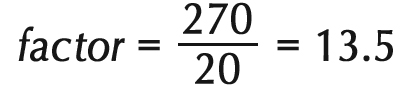
Now, measure the voltage on the cathode of D4 and multiply it by the factor used. This will give you (approximately) the correct voltage of the circuit.
If you use another tube besides the LND 712, check its specifications for the voltage needed to drive the tube.
RECORDING USING WINDAQ
I normally record an event once per minute. Make sure you are only using one recording channel. To record, click “File” and then “Record.” Make up a file name that you can remember. Once you name it, a window will pop up and ask for the number of kilobytes. Make sure you put enough in for 24 hours of recording. You can do this by holding down OK, and observing the hours and minutes. If this is not correct, move the arrow off of OK and input more or less KB. Click OK when finished.
You can change the units by clicking on “Edit.” Go to the engineering unit settings and make five volts = 4096 counts.
When finished recording, click “File” and then “Close.”
REVIEWING DATA
Perform a search with the name you stored the data in. Click on it and the Windaq software should open. Press F7; it may take a few seconds to load. Click on “Maximum.” The display should have 24 hours of data on one page.
REFERENCES
The first Geiger counter I had was back in 1989 and was an Aware Model RM-60. They are still manufacturing counters, but they start at about $180. They make a good product, however. On their website (www.aw-el.com), they have a lot of information on Geiger counters, including sites to experimentation. They also have methods of measuring radon that can be applied to this unit.
Check out https://sites.google.com/site/diygeigercounter/gm-tubes-supported for more information on different Geiger tubes.
Downloads
Radiation Counter Download Pak (Includes PIC code)
**File Updated 04/21/2014**