ImageCraft is giving away three JumpStart MicroBoxes to randomly selected Nuts & Volts readers. Just send an email on March 31, 2016 or earlier to [email protected] with the words NUTSNVOLTS-GIVEAWAY in the subject field to qualify.
There is a special place in my heart for the CCS C compiler. C compilers that target the PIC microcontroller are numerous. However, the CCS C compiler has a unique touch and feel. The flavor that this C compiler exhibits is directly coupled to its abundance of built-in functions that are specifically aimed at PICs. If your target microcontrollers are ARM-based, the same can be said for JumpStart C for Cortex-M. JumpStart C is an ARM Cortex-M C compiler environment that utilizes the ImageCraft JumpStart C API to enable rapid ARM application development. The JumpStart C API provides an abstraction layer that encapsulates the minute details associated with ARM microcontroller programming. JumpStart C for Cortex-M comes packaged within its own IDE (integrated development environment) and even includes a resident debugger.
Passing Muster
For JumpStart C for Cortex-M to be useful, it must be flexible. Many of the ARM development boards offer onboard programming/debugging via STMicroelectronic’s ST-LINK/V2 or Segger’s J-Link OB. JumpStart C is capable of supporting both onboard debugger/programmer solutions. However, if you design microcontroller based gadgets for a living, odds are you won’t be offering your design to a customer by way of an off-the-shelf ARM development board. So, like CCS C for PICs, JumpStart C must also be able to interface to the professional tools that support ARM microcontroller application development. In my ARM world, that professional tool comes in the form of a Segger J-Link PRO.
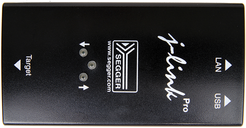
PHOTO 1. The J-Link PRO is a versatile microcontroller development tool. In addition to ARM, the J-Link PRO supports application development with Microchip’s PIC32 and Renesas.
The Segger J-Link PRO captured in Photo 1 is a very capable ARM development tool. The J-Link PRO is actually a refined version of the standard J-Link. The J-Link PRO adds an Ethernet interface and a pair of additional LEDs which act as status indicators. Choose your poison: Windows, Linux, or MAC. The J-Link PRO can operate with them all using either its Ethernet or USB interface. SWD (Serial Wire Debug) and JTAG interfaces are supported. I don’t think you can throw an ARM microcontroller at the J-Link PRO that it doesn’t know about.
According to Screenshot 1, the JumpStart C development environment embraces both the ST-LINK/V2 and J-Link PRO. There is only one way to insure that the radio button selections we are privy to in Screenshot 1 will yield the required result.
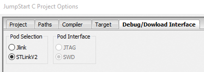
SCREENSHOT 1. All we have to do is make sure that the correct J-Link and ST-LINK/V2 drivers are installed. JumpStart C can take it from there.
ARMing a Serial Port
When it comes to serial ports, timing is everything. So, we have to first initialize our system clock. JumpStart C takes the pain out of clock configuration with the SetSystemClock function:
jsapi_clock.SetSystemClock(8,0,0,0,48);
The STM32F030R8T6 based development board you see in Photo 2 has printed circuit board (PCB) pads for an external crystal, which are not loaded by default. That means (for now) our SetSystemClock function call will have to specify the system clock source as internal (HSI). This is signified by the 8 in our function call. The units are MHz, so to get a final PLL-generated 48 MHz system clock, we simply end our SetSystemClock function call with 48. The SetSystemClock function along with all of the other JumpStart C API is documented in the Jumpstart API for STM32F0xx and STM32F4xx document.
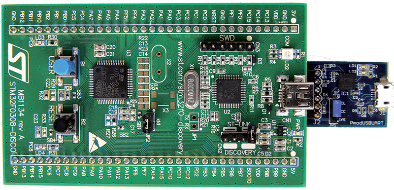
PHOTO 2. This is a stock STM32F030R8T6 Discovery evaluation platform. It has been modified to accept the 20-pin J-Link programmer cable. A Digilent PmodUSBUART module has been added at the opposite end of the perfboard that comes with the evaluation board. The main board plugs into the perfboard.
To keep you from straining your neck going back and forth between the API specification and your application code, the JumpStart IDE automatically displays helper API call syntax as you enter the API call in your source code. While we are talking clocks, let’s go ahead and set up a SysTick timer:
jsapi_cortex_core.SysTick_Timer(SYSTICK_MILLISECOND);
Every millisecond, an interrupt will be generated and the JumpStart API can (and will) use this interrupt to keep time. This will enable us to use the JumpStart API delay functions. We can now turn our attention to the configuration of the USART. The STM32F030R8T6 supports a pair of USARTs. We will activate USART2:
usart2.SetPins(&porta, 2, 1, &porta, 3, 1);
The transmit pin for USART2 is located on PORTA, pin 2 (PA2). The receive pin is defined as PORTA, pin 3 (PA3). The Alternate Function Register for both transmit and receive alternate functions is AF1, which is denoted by the pair of 1s in the SetPins function argument.
Now that our USART pins have been defined and activated, we can set the USART’s baud rate, number of data bits, number of stop bits, and flow control:
usart2.MakeUSART(9600, 8, 1, 0);
Let’s combine our clock and USART code into a single function called Setup:
static void Setup(void)<br />
    {<br />
    jsapi_clock.SetSystemClock(8,0,0,0,48);<br />
    //jsapi_clock.SetSystemClock(0,0,8,0,48);<br />
    jsapi_cortex_core.SysTick_Timer<br />
    (SYSTICK_MILLISECOND);<br />
    usart2.SetPins(&porta, 2, 1, &porta, 3, 1);<br />
    usart2.MakeUSART(9600, 8, 1, 0);<br />
    }
The commented SetSystemClock entry is the code we can use to configure our system clock as HSE with an external 8 MHz crystal.
At this point, we can bang single characters through our new USART at will. However, having the ability to employ the features of the printf command allows us to easily send formatted messages via our USART. To get printf into the game, we need to write a local or top level putchar function that will override the putchar function that is contained within the stdio library:
int putchar(unsigned char ch)<br />
    {<br />
    if (ch == ‘\n’)<br />
        usart2.putchar(‘\r’);<br />
    usart2.putchar(ch);<br />
    return ch;<br />
    }
Our top level putchar function utilizes the JumpStart API putchar call. This allows us to use the printf function in our code. We should now be able to write some serial transmission code that can use printf formatting. We also configured a SysTick timer that should enable us to code in a delay between transmissions. Here’s the resultant source:
int main(void)<br />
    {<br />
    Setup();
    while (1)<br />
        {<br />
           printf(“Design Cycle is ARMed\r\n”);<br />
           DelayTenth(5);<br />
       }<br />
    return 0;<br />
    }
If all works as designed, our little app should transmit the Design Cycle message every half second. Before we can see any results, we need to install some serial port hardware. The STM32F030R8T6 evaluation board captured in Photo 2 has been modified to accept the J-Link PRO 20-pin programming cable. On the opposite end of the STM32F030R8T6 board, a Digilent PmodUSBUART module has been wired in. It’s a simple connection.
The Pmod’s TX pin is connected to the STM32F030R8T6’s PA3 RX pin. PA2 — the STM32F030R8T6’s TX pin — is connected to the Pmod’s RX pin. No power connections other than GND are necessary as the Pmod is powered from its USB portal. I used a six-pin, right angle, 0.1 inch pitch female socket to mount the Pmod. The USART program compiled without error. A debug session was kicked off with the J-Link PRO connected to the STM32F030R8T6. I fired up the CCS SIOW terminal emulator and configured it for 9600 baud. Once the emulator came up, I was presented with a pair of green LED status indicators on the J-Link PRO and a blinking transmit LED on the Pmod. Screenshot 2 confirms our success with the ARM USART.
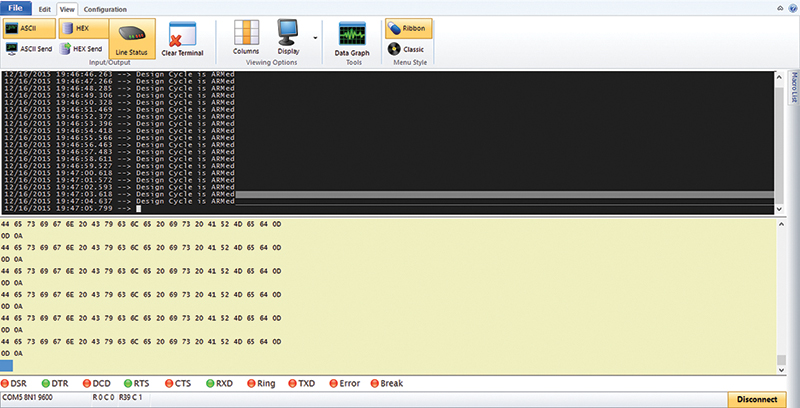
SCREENSHOT 2. This screen capture leaves no doubt that our application of the JumpStart API is working as designed. Don’t get too excited about the time stamps. These times are relative to the terminal emulator, not our STM32F030R8T6 SysTick timer.
I SPI
Now that we have established a working USART portal that we can use as a debug tool, let’s bring up another important communications port we all know as the SPI portal. We shall begin by consulting the STM32F030R8T6 datasheet and laying out the SPI MOSI, MISO, SCLK, and CS pins:
    spi1.SetPins(<br />
           &porta, 5, 0,        // SCK<br />
           &porta, 7, 0,        // MOSI<br />
           &porta, 6, 0,        // MISO<br />
           &portb, 6,          // CS<br />
       true                   // active LOW<br />
                );<br />
    spi1.MakeSPI(8, 0, 400000);
The STM32F030R8T6 datasheet tells us that the SPI1 pins are located on PORTA in AF0 (Alternate Function 0). The SPI CS pin is not datasheet assigned. So, PB6 is just as good as any here. The CS pin is configured as active low. I have plans for this SPI portal. So, for now, we will configure it as an eight-bit portal running in SPI mode 0 at 400 kHz. SPI mode 0 equates to a clocked data stream with phase low (CPHA = 0) and polarity low (CPOL = 0). Now that we have defined, configured, and activated our SPI portal, the JumpStart API supports it with a load of SPI data transfer calls.
For instance, we can send eight bits of data to an SPI slave with this JumpStart API call:
bite = spi1.Write(data);
As you can see, the spi1.Write call also returns a byte of information from the slave. If the application calls for 16 bits per transfer, all we have to do is alter our spi1.MadeSPI call like this:
spi1.MakeSPI(16, 0, 400000);
Controlling the SPI chip select (CS) line is also covered by the JumpStart API:
  spi1.ChipSelect();        //CS = low<br />
  spi1.ChipDeselect();    //CS = high
Remember that I stated earlier that I had a “plan” for our SPI portal?
microSD ARMed
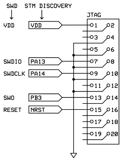
The reconnaissance data captured in Photo 3 reveals that a microSD card socket and associated components have been added to our STM32F030R8T6 ARM complex. The microSD card socket assembly is mounted on top of the six-pin Pmod access socket. Everything is wired in using point-to-point techniques. Schematic 1 outlines the attachment of the 20-pin JTAG programming/debugging header.
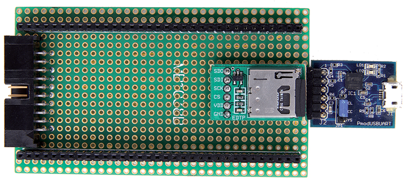
PHOTO 3. The microSD card socket and buffer circuitry are mounted on top of the Pmod six-pin socket.
SCHEMATIC 1. This is the classic SWD-to-JTAG translation. This lashup allows us to connect the J-Link PRO without the need for any special adapter cabling.
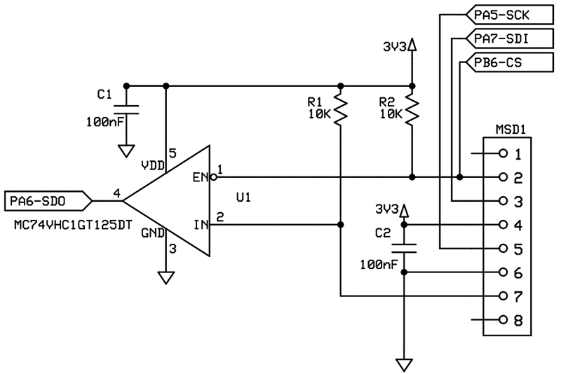
The microSD circuitry is outlined graphically in Schematic 2. The tristate buffer in the design provides output buffering, as well as isolation from the STM32F030R8T6’s SPI MISO line.
SCHEMATIC 2. The advantage of this design is that the output of the microSD card is buffered and isolated.
The microSD’s MISO and CS signals should be pulled up, and we have done just that in our circuit design.
The hardware is fairly straightforward. Thanks to the JumpStart API, the firmware is too. The JumpStart API package includes a number of example projects including a microSD project that implements the open source FatFs. FatFs is a generic FAT file system module. The example FatFs core files in my JumpStart API package were down a level. So, I downloaded the current set of FatFs core files and replaced them in the JumpStart API example code.
The replacement of the existing FatFs core files necessitated changes to the JumpStart API’s fatfs_diskio_sdcard_spi.c file. The changes involved syncing the variable type declarations in the fatfs_diskio_sdcard_spi.c file with those in the latest FatFs integer.h file. Don’t worry; I’ve included my updated file in a download package for you at the article link.
Let’s see if we can get this microSD thingie to work. Since reading and writing the SPI portal is key, we’ll need to package the JumpStart API SPI write call into a function:
unsigned char spi_txrx(unsigned char data)<br />
    {<br />
    return spi1.Write(data);<br />
    }
The fatfs_diskio_sdcard_spi.c file is a combination of low level SPI routines coupled with glue functions that tie the low level SPI functions to the upper level FatFs application calls. The JumpStart API example is well written, but it is wordy. The best way to get our arms around it is to work using the FatFs Device Control Interface as our reference point. The Device Control Interface is predefined in the FatFs specification. It consists of six calls:
disk_status — Get device status
disk_initialize — Initialize device
disk_read — Read sector(s)
disk_write — Write sector(s)
disk_ioctl — Control device dependent features
get_fattime — Get current time
Let’s take a look at the disk_status interface call:
typedef BYTE DSTATUS;
typedef struct hwif<br />
{<br />
  int initialized;<br />
  int sectors;<br />
  int erase_sectors;<br />
  int capabilities;<br />
} hwif_t;
hwif_t hw = {0,0,0,0};
DSTATUS disk_status(BYTE drv)<br />
{<br />
  if (hw.initialized)<br />
    return 0;
  return STA_NOINIT;<br />
}
I’ve taken the liberty to assemble associated items found in supporting files. The structure variable hw.initialized is influenced by lower level calls and operations. All that FatFs cares about the variable is that it has a valid value when FatFs comes to call for disk status at the application level.
The disk_initialize interface depends on the outcome of the hwif_init function. The final state of the hwif_init function is dependent on the results of the sd_init function:
int hwif_init(hwif_t* hw)<br />
{<br />
  int tries = 10;
  if (hw->initialized)<br />
    return 0;
  while (tries—)<br />
  {<br />
    if (sd_init(hw) == 0)<br />
      break;<br />
  }<br />
  if (tries == -1)<br />
    return -1;
DSTATUS disk_initialize<br />
(BYTE drv)<br />
{<br />
  if (hwif_init(&hw) == 0)<br />
    return 0;
  return STA_NOINIT;<br />
}
The sd_init function is lengthy. So, let’s assimilate it in the way we would go about eating an elephant. The SD card specification says to begin by sending 74 or more clocks to the microSD card with the CS signal logically low:
  printf(“cmd0 - reset.. “);<br />
  spi1.ChipSelect();<br />
  spi1.ChipDeselect();<br />
  /* 74+ clocks with CS high */<br />
  for (int i = 0; i < 12; i++)<br />
    spi1.Write(0xFF);
As you can see, the JumpStart API spi1 calls make this a simple matter. The next step involves reading the microSD card and interpreting the response, which is called R1 in the spec:
   /* reset */<br />
  spi1.ChipSelect();<br />
  sd_cmd(0,0);<br />
  r = sd_get_r1();
static BYTE sd_get_r1(void)<br />
{<br />
    int tries = 1000;<br />
    BYTE r;
    while (tries— != 0) {<br />
        r = spi_txrx((BYTE)0xff);<br />
        if ((r & 0x80) == (BYTE)0)<br />
            return r;<br />
    }<br />
    return (BYTE) 0xff;<br />
}
If you follow through the sd_init code in your download package, you will see that we ultimately want to see an R1 response value of 0x01. The R1 bit scheme is laid out in Screenshot 3.
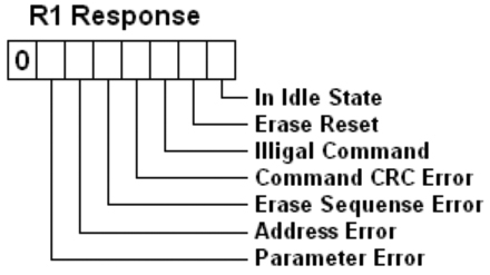
SCREENSHOT 3. The R1 response byte value we are looking for after the 74+ clocks is In Idle State.
We’re off to a good start. Screenshot 4 informs us that the microSD card has come to life.
SCREENSHOT 4. So far, so good. Now that we have the microSD card’s attention, we can issue all sorts of commands to gather configuration information.
At this point, we can issue other microSD card commands to gather configuration information and even read the card. The demo contains various commands which are embedded into the sd_init function. However, the sd_init function does not issue any FatFs commands to actually read a file. So, I have added some file access code to the main.c code:
FATFS   FatFs;<br />
FIL     fil;<br />
char   line[32];<br />
FRESULT fr;
    f_mount(&FatFs,”“,0);<br />
    fr = f_open(&fil,”message<br />
    .txt”,FA_READ);<br />
    if(fr)<br />
        return (int)fr;<br />
    while(f_gets(line,sizeof<br />
    line,&fil))<br />
        printf(line);<br />
    f_close(&fil);
The text file message.txt contains a single string of characters. The FatFs code snippet mounts the volume, opens the file in read only mode, and retrieves the string into the line array. The contents of the array are then sent to the serial port. Once the file contents have been read and displayed, the text file is closed.
The FatFs top level commands make it look easy. Study the fatfs_diskio_sdcard_ spi.c code and you will see that there are many supporting functions that perform the actual reading and writing of the microSD card media.
Does It Work?
Well, we know that the USART is operational. We also know that we can successfully bring up the microSD card. Before we turn the rest of the sd_init code loose, let’s fiddle with the hardware again. Recall that I coded (and commented out) a line to drive the STM32F030R8T6 from an external 8 MHz crystal:
 jsapi_clock.SetSystemClock<br />
(8,0,0,0,48);     <br />
    //HSI internal clock<br />
//jsapi_clock.SetSystemClock<br />
(0,0,8,0,48);    <br />
    //HSE 8MHz crystal clock
Let’s remove the comment characters from the HSE code, comment the HSI clock code, and run the final test using the HSE clock instead of the internal HSI clock.
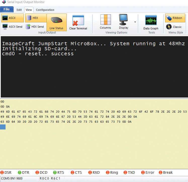
The command execution follows the source code found in the main.c file (in the examples.JumpStart
MicroBox/STM32F030/SDcard folder) and fatfs_diskio_sdcard_spi.c file, which is located in the examples.JumpStartMicroBox /FatFs folder. The last thing we should see is the contents of the message.txt file. I let the microSD card code run all the way through. It produced the information you see captured by the SIOW program in Screenshot 5. I loaded the microSD card socket with a 16 GB SDHC microSD card. All of the data on this card we could extract is listed in the Screenshot 5 report.
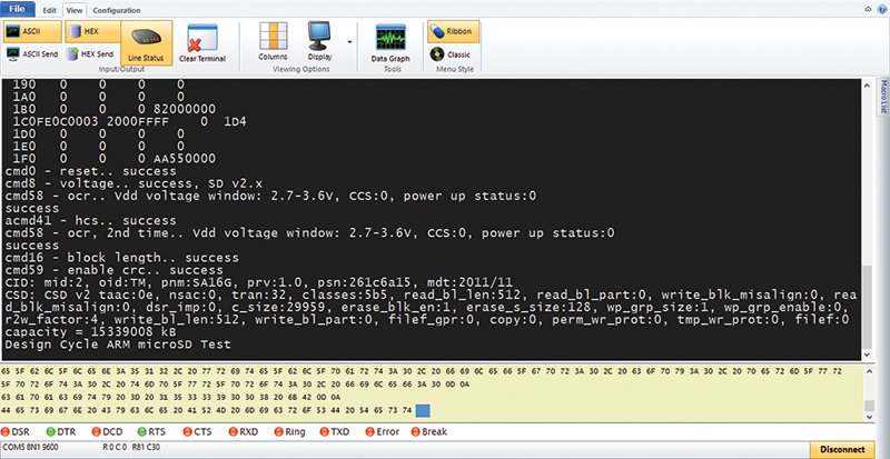
SCREENSHOT 5. The command execution follows the source code found in the main.c file (in the examples.JumpStartMicroBox/STM32F030/SDcard folder) and fatfs_diskio_sdcard_spi.c file, which is located in the examples.JumpStartMicroBox/FatFs folder.
I’ll leave you with Photo 4, which reveals an STM32F030R8T6 Discovery Board with the addition of an 8 MHz crystal, its associated components, and a 32.768 kHz clock crystal with its set of capacitors.
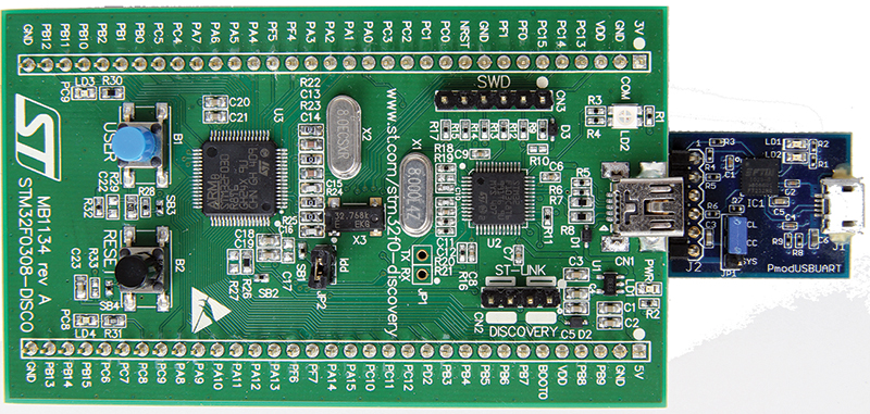
PHOTO 4. In this shot, you can see the additional capacitors, resistors, and crystals that are absent in Photo 2. The steps needed to add these components are outlined in the STM32F0 Discovery user manual.
You can now add the JumpStart API and STM32F030R8T6 to your Design Cycle. NV
JumpStart API
JumpStartMicroBox
ImageCraft
www.imagecraft.com
J-Link PRO
Segger
www.segger.com
CCS C Compiler
CCS, Inc.
www.ccsinfo.com
Digilent
PmodUSBUART
www.digilentinc.com
Downloads
What’s in the ZIP?
FatFS
main.c
SDCard.hex