It’s fun — and easy — to bring your vintage radio back to life!
Maybe you were digging around in the attic helping your parents downsize, and found their old wooden tube radio from many years ago stashed away. Or, perhaps you've inherited your grandparent's precious tube console — now a family heirloom — that stood as the centerpiece of their living room for many years. Even though they're ancient by today's standards, these old tube radios can almost always be brought back to life, and there's still plenty of broadcasts out there for them to receive! Not to mention, they just look so classy and have a presence few modern electronics can match.
Fixing up a vintage radio is a little different from fixing up many other types of gear, since the entire field of electronics had only just been invented when they were first made. We were still learning the engineering and physics underlying all this new technology.
Competing standards emerged and fell by the wayside, and huge advances were made in the span of only a few years — not to mention some vicious patent wars — which all mean that no two radios are alike.
Even still, since radio was the only means of home entertainment for decades, there's plenty of service information out there to help you through the process, and there's nothing quite like the feeling of hearing a piece of history crackle back to life after a successful repair job.
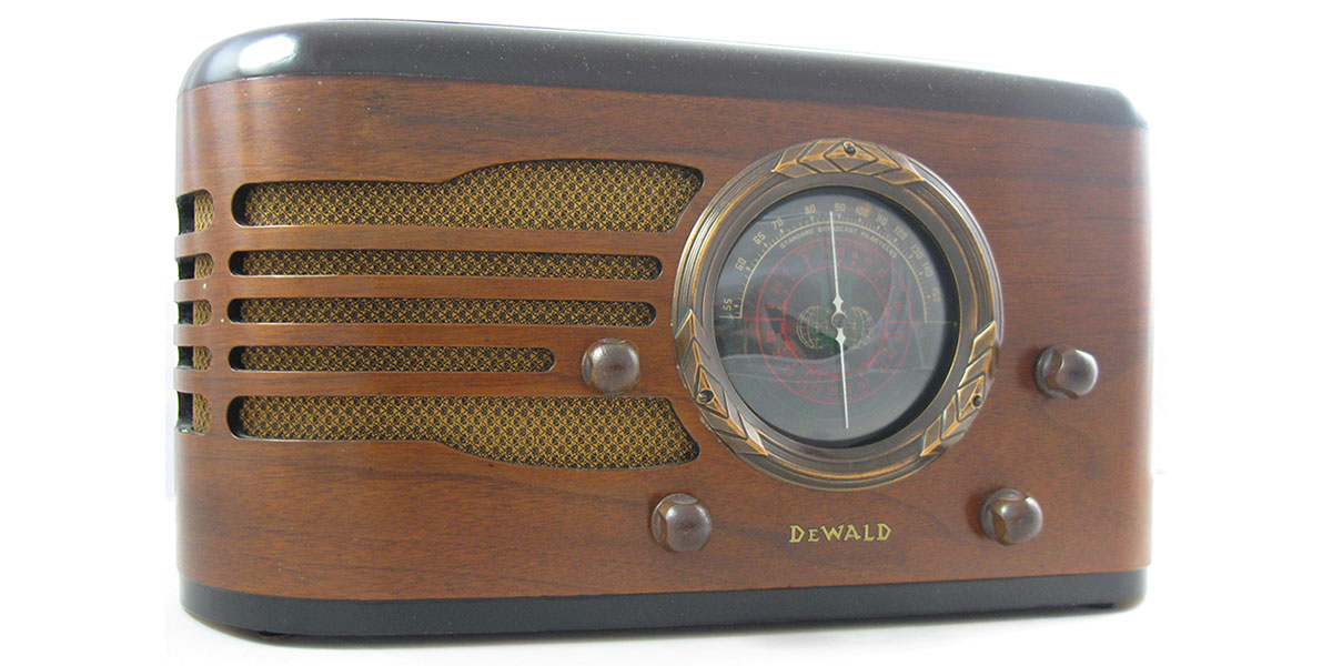
Over a series of articles, I'll be performing a full electrical restoration on a 1937 DeWald Model 618 vintage radio from start to finish: evaluating its condition, performing the restoration work, and aligning and verifying its performance after service is complete. In this first article, I'll cover some tips for what to look for on your old radio to judge its condition, and do a full inspection of the internals to see what work will need to be done.
First, a Short History Lesson
Vacuum tubes operate on the principle of thermionic emission, where certain metals heated to white-hot in a vacuum will give off electrons. The flow of these electrons can then be controlled by charges placed on the tube's internal elements. The first practical vacuum tubes were invented in 1907 by Lee DeForest, who developed the "Audion" — the world's first triode capable of amplification. This ushered in the radio age, but it wasn't until about 20 years later that radio finally left the lab and made it to consumer's homes.
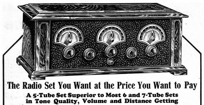
An early radio with multiple controls; the Barawick Five (Popular Mechanics, November 1926).
Even then, most radios still operated on stacks of expensive batteries which had to be replaced often to deliver the high voltages necessary to operate. It wasn't until widespread electrification of the United States and the development of tubes which could be heated with AC power instead of DC at the very tail end of the 1920s that radio exploded and achieved mass-market status.
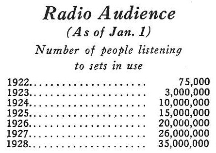
Radio's listening audience grew rapidly in the early days (Radio Retailing, March 1928 via "Radio Manufacturers of the 1920s" by Alan Douglas).
Stacks of batteries disappeared and radios went from being pieces of lab equipment with many controls to adjust independently to the format we've retained today. Point the needle to the station on the dial and off you go.
Unlike transformer-operated radios which are inherently isolated, many more economical radios saved the cost of the transformer and connected the radio's circuitry directly across the AC line. This can result in a significant safety hazard as now the radio's metal components may become "hot" relative to ground. You could receive a fatal shock by accidentally contacting a cold water pipe or damp concrete floor, or destroy any grounded test equipment you connect to the device under test.
An isolation transformer will interrupt the current path to earth ground and provide safety in these circumstances — both for yourself and your equipment. Most isolation transformers are 1:1, although tapped models with provisions for slightly adjusting the line voltage (i.e., 120:115-120-125) and continuously variable models do exist. Don't use a variac, though — they're not isolated and won't provide any safety benefits — unless you have a separate isolation transformer to go with it.
Caution!
Electronics of the era were really brute-force devices, and tube radios were no exception. It is incredibly important you follow proper safety precautions while working on any tube radio as they present some different hazards than most other hobbyist projects which run on a dozen or so volts. Even an entry-level radio from the '20s or '30s might have as much as 500V DC (with 50-100 mA of current available!) on the tube's plates in the circuit.
Safety standards were nearly non-existent, and it was common to find certain transformerless "AC/DC" radios with one side of the incoming power connected to the chassis. In a modern household system, this could place 120V AC on any exposed metal bit.
In addition to all these electrical hazards, tube radios get quite hot while operating, and you can easily get a serious burn by grabbing a tube before it's cooled. Always work with the radio unplugged, and when testing a powered-on radio, use one hand. If you're working on a hot chassis radio, make sure to use an isolation transformer or you could be badly injured or killed. Go slowly, double-check your work, and be careful!
If you find a radio in the attic, you might be tempted to plug it in and see if it works before getting started. Do not ever do that! Signal routing in these vintage radios was primarily done with capacitor coupling, and the capacitors back then were literally made out of cardboard, foil, paper, and wax which badly degrade with age.
Odds are that if you try and plug in a radio you've just found, not only will it not work, but shorted capacitors will damage expensive and difficult to replace components like transformers, or even start a fire. It only takes a few seconds. Never power-on a vintage radio without inspecting it, and at a minimum replacing the capacitors!
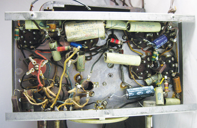
Underside of the radio showing mostly original capacitors, but with a few more recent replacements.
Finally, if you've found a project radio to start on with more than six or seven tubes, you might want to find a smaller model to practice on before diving in — especially if the radio has any sentimental value to you. The number of tubes gives a good estimate of the circuit complexity, and even if you're skilled at electronics they're different enough from most projects that it's good to get a feel for how tube circuits work before starting on that special radio.
So, What Do I Need?
For most radios, you don't need much at all. It's entirely possible to do a full radio restoration with nothing but a multimeter, a soldering iron, and your standard assortment of screwdrivers, pliers, and clippers. If you're working on a "hot chassis" radio which lacks a main power transformer, you'll want to use an isolation transformer. If you're a perfectionist, you may want a modulated signal generator to help out with the alignment. In general, these are simple pieces of electronics and you don't need much to be successful. That's the best part — no special tools required!
Most of the components you'll use can be obtained from everyday electronics parts houses like NTE PartsDirect or Mouser. If you're just starting out — or just don't care to wade through some of those more complicated sites to find what you're looking for — specialty retailers like New Sensor (www.newsensor.com), Sal's Capacitor Corner (www.tuberadios.com) or Just Radios (www.justradios.com) have a more focused selection of parts specifically for these kinds of projects.
More often than not, the tubes that are already installed in your radio are good and don't need to be replaced. If they do, though, you can find most tubes at Antique Electronics Supply (www.tubesandmore.com). There's a thriving hobbyist community with thousands of active members from around the world (myself included!) over at the Antique Radio Forum (www.antiqueradios.com) to help you out if you need to find something specific and/or rare, or if you'd just like to chat about your new project.
Basic Visual Inspection
If you've already found a radio, now it's time to check it out a bit. I'll be using my DeWald 618 as an example.
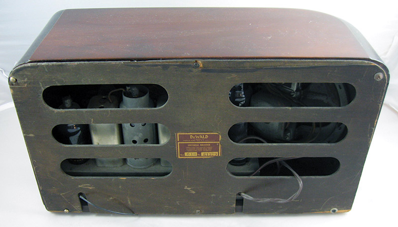
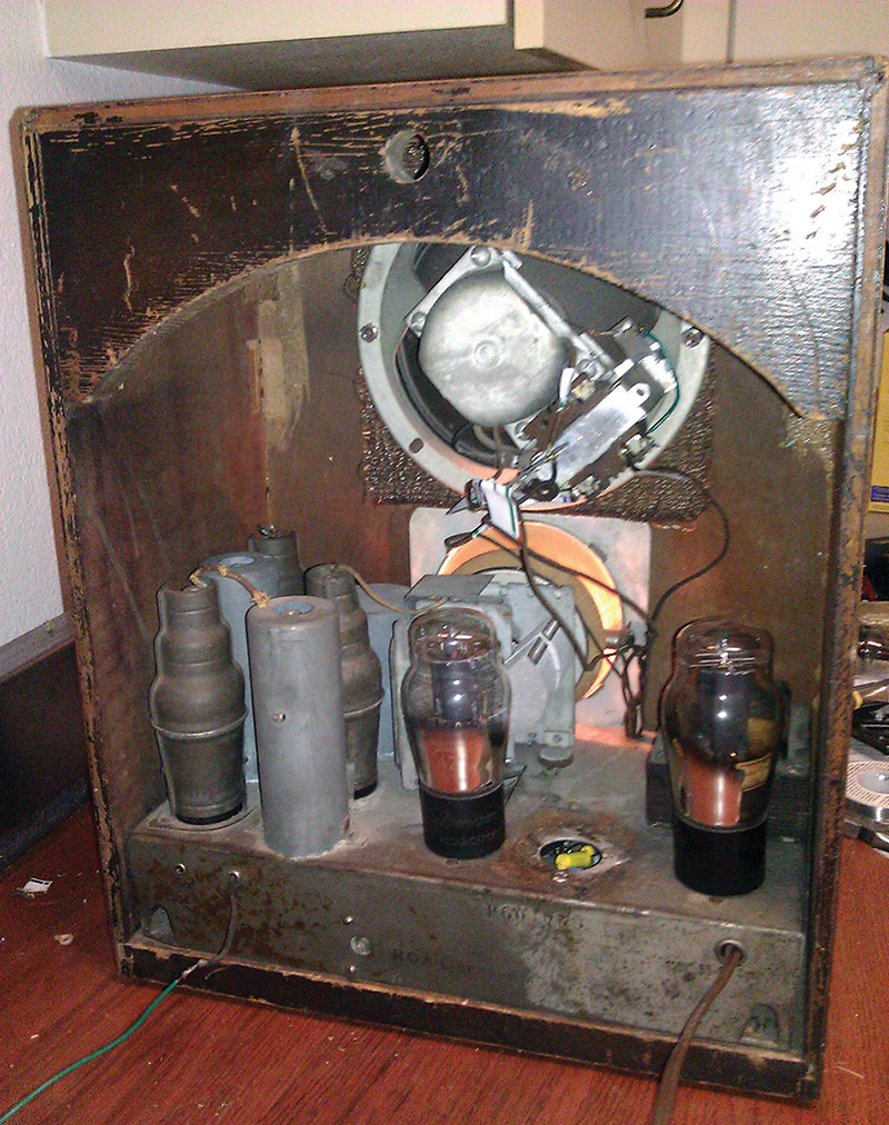
The rear of the DeWald 618, with the rare original back intact.
First, take a good look at the back of the cabinet. Do you see any signs of smoke damage? If so, that would be a big red flag. Fortunately, it's pretty rare to find one that's been on fire previously, so most of the time you'll be looking for more subtle problems.
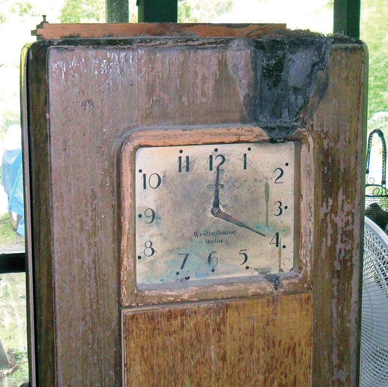
This 1931 Westinghouse grandfather clock radio which was previously on fire wouldn't be a good starter project.
These radios have been around a long time and were often in the shop every few years when they were new, so it's worth checking for a few things. If your radio has a large power transformer, check to see that it hasn't overheated and melted the potting tar out from the insides. This generally means a burned out transformer and a dead radio, and is one of the most common outcomes if you plug in a radio you've found without refurbishing it first.
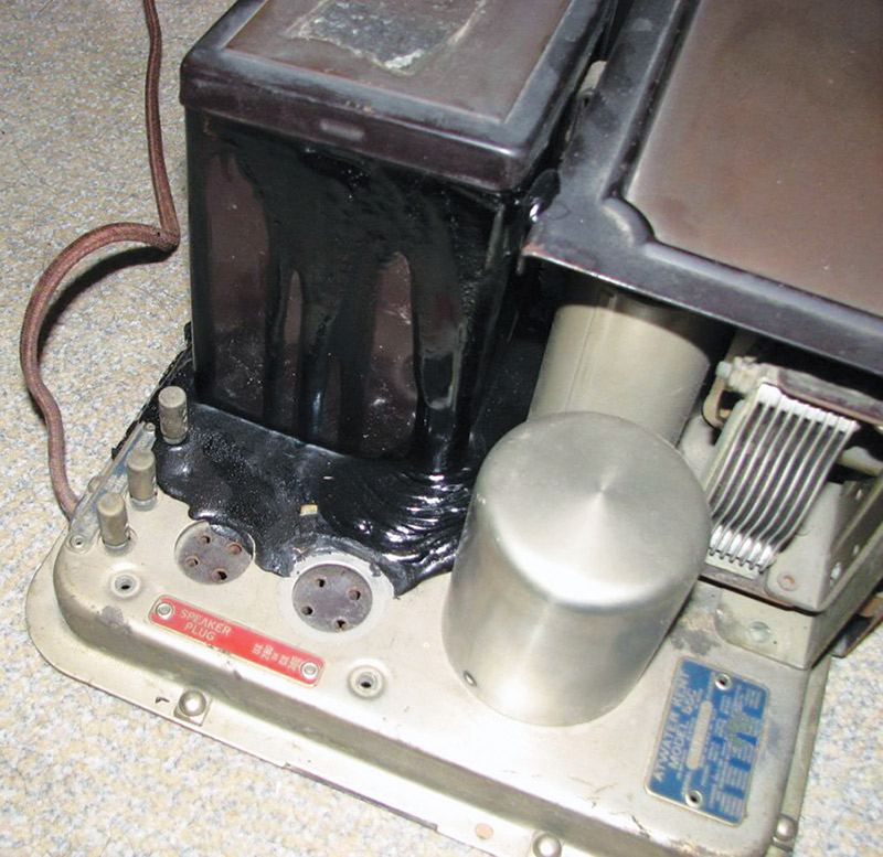
This radio had shorted filter capacitors in the power supply which caused overcurrent, overheating, and melting in the power transformer.
Keep an eye out for evidence of rodent or insect infestations. Bite marks and chewed wiring are a major warning sign. Generally, a radio that's been infested isn't worth even attempting to fix due both to the damage that may exist and the fact it's a serious health hazard.
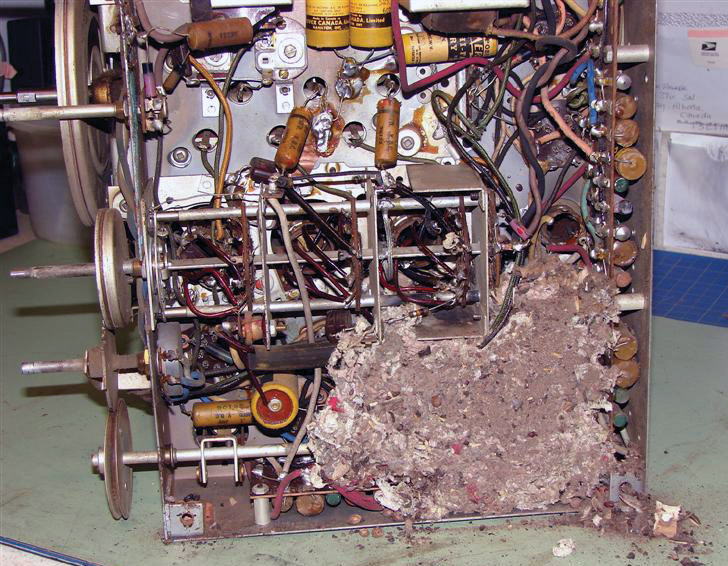
A vintage radio chassis infested with mice. Not a good candidate for repair!
Finally, keep an eye out for modifications made sometime in the past. Empty holes on the chassis, extra bolted-on parts, or things that just don't belong are evidence of someone having been in there before. That's not necessarily bad, but it means you'll need to carefully check the radio out.
This Simplex Model P tombstone radio has an extra bolted-on output transformer, and is missing a filter capacitor can.
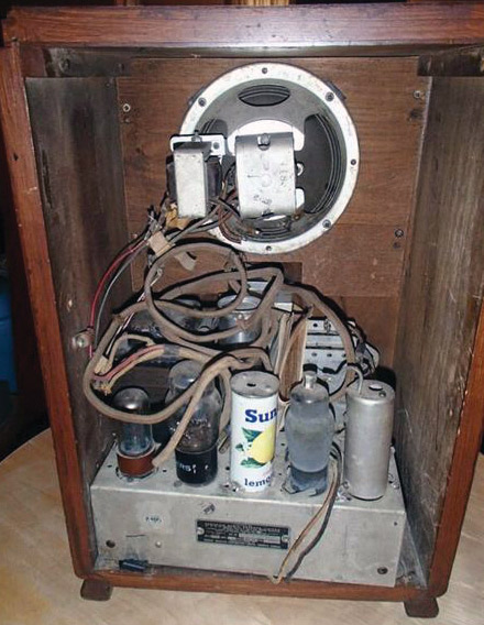
Someone replaced an IF transformer on this 1935 Rogers radio with a juice can.
There are two kinds of radios: superheterodyne or "superhet;" and tuned radio frequency or "TRF." These relate to differences in the way they process the radio signals, but all share mostly the same set of parts.
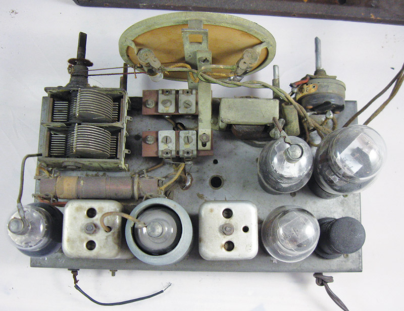
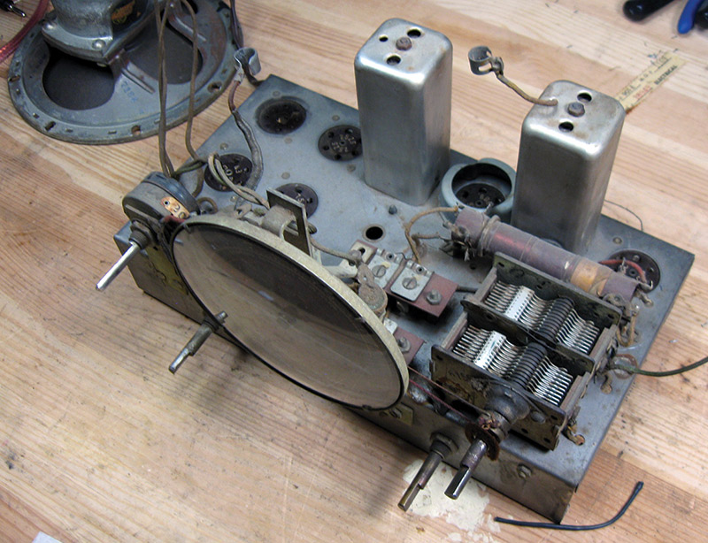
The DeWald 618 chassis from the top down.
There's a power supply which typically had one or two inductors for filtering. From the antenna, there will be a set of antenna coils which are radio frequency (RF) transformers used in pre-selecting the tuned station. There's further sets of RF coils depending on the radio's topology: more RF coils for a TRF, or a set of oscillator coils and intermediate frequency (IF) transformers.
Finally, there's the audio output section which will have an output transformer which drives the speaker, and occasionally an interstage transformer as the input to the audio amplifier stage. All of these coils and transformers need to be working for the radio to receive correctly.
Principles of Operation
The DeWald 618 is a superhet. In this five-tube AC/DC radio, the antenna picks up the transmissions and couples them through a set of antenna coils which are switched depending on whether you're listening to mediumwave broadcast signals or one of the shortwave bands, and help to pre-select the signal going into the next stage of the radio to reduce interference and undesired reception.
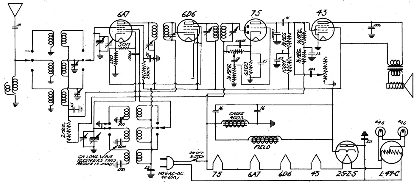
Original schematic for this radio from Rider's Perpetual Troubleshooter Vol. 7.
This signal is fed into the 6A7 tube — the pentagrid converter which serves the double function of both local oscillator (driven by a set of oscillator coils) and mixer.
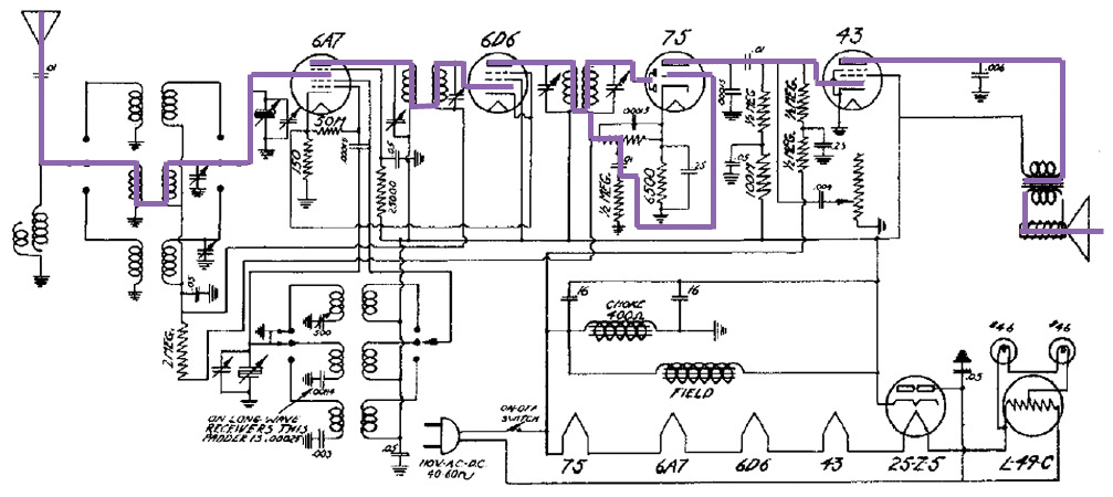
The schematic showing the signal path from the antenna to the speaker.
After mixing the RF signals together, the converter outputs the received signal on the radio's IF. This IF signal is first coupled through an IF transformer, tuned to the intermediate frequency, and into the 6D6 IF amplifier tube.
After being amplified, the signal exits the plate of the IF amplifier and travels through another IF transformer to the #75 tube which is the combined detector, audio amplifier, and automatic volume control level generator. The diodes in the #75 tube detect (rectify) the modulated RF signal, into wave riding on top of a DC offset.
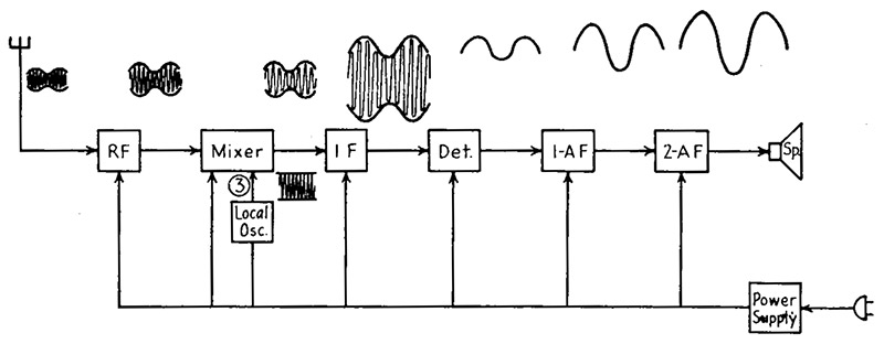
Block diagram showing the signal path through the radio, with wave shapes shown (Elements of Radio Servicing, Marcus and Levy, 1947).
In most radios, this DC level is proportional to the received signal strength and is routed to the radio's front-end tubes as a part of the automatic volume control (AVC) circuit. This helps keep the radio's volume constant as you tune around the dial and as the strength of the radio signal naturally fluctuates due to atmospheric conditions. The audio riding on top of the DC is passed through a capacitor and the volume control, and into the control grid (input) of the #75 where it exits the plate and drives the #43 output tube. The signal travels from the #43 through an output transformer and reproduces the program's audio to your ears via the speaker.
In-Depth Intake Checks
Before getting started with the labor of replacing components, it's useful to check the status of all the coils and transformers. These parts are all called out on the schematic.
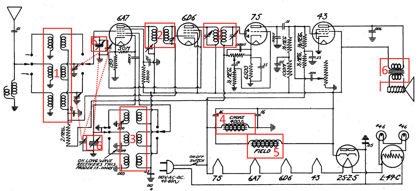
Components as marked: (1) Antenna coils; (2) IF transformers; (3) oscillator coils; (4) filter choke; (5) field coil; and (6) output transformer.
After pulling the chassis and speaker from the cabinet, the first step is to remove the tubes.
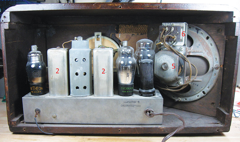
Back side of the radio showing components labeled.
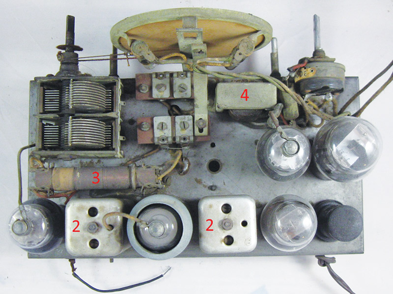
Top-down view showing other components labeled.
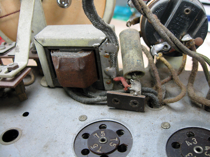
Make a note of which tube goes in which socket since they're not interchangeable. Some radios (like the one I’m using here) have the tube number stamped into the sockets — if that's the case, you're lucky!

Bare radio chassis with tubes removed.
If any of the tubes have a top cap with a wire connection, be careful when removing it — sometimes the top caps of the tubes have come loose with age and can be pulled off which often ruins the tube.
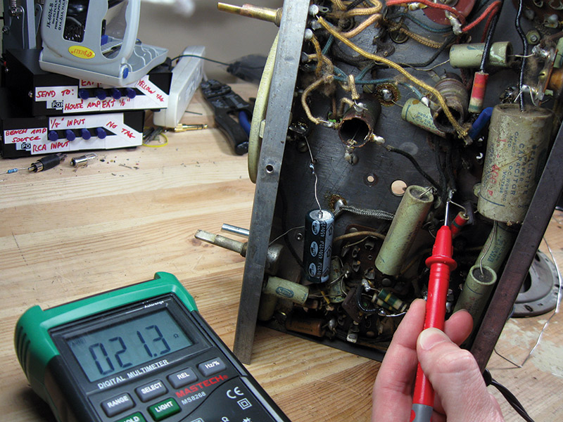
With the tubes removed, now you can access the various connections a bit more easily. I like to start with the radio's front end with the antenna coils, and move through the radio to the output transformer. To check their condition, simply use a multimeter set to measure resistance (ohms) and check for continuity.
An infinite resistance reading means there's a broken wire, but good readings might range from a few ohms on the low end to a few dozen on the high end.
Measuring the primaries of the antenna coils.
One good trick for measuring the primary of the antenna coils is to take advantage of the radio's built-in wiring. Since the antenna connects to all of these coils and all of these coils connect to ground after the band switch, connect the multimeter between the antenna terminal on the back and ground, and flip through the ranges. In this case, all good! I measured the secondaries of the antenna coils as well, and they also checked out. On to the oscillator coils!
This radio has three oscillator coils total: one on its own coil form beneath the chassis, and two wound on the same coil form and mounted up next to the variable capacitor on the top.
Measuring the lower oscillator coil.
The other two oscillator coils sharing a common coil form on top of the chassis.
These are each four-terminal devices, so they're easy to check out. There will be two sets of lugs with continuity to each other, but not to the lugs from the opposite winding. In this case, all oscillator windings tested good too.
Next up are the IF transformers. These cans are mounted to the chassis, and each has two windings: a primary and a secondary. It's fairly straightforward to trace out the wiring and find two pairs which have continuity.
On the first IF transformer, the secondary has one connection out the top to the grid cap of the 6D6 IF amplifier tube. On the second IF transformer, they're both on the bottom. After checking continuity on both, the IF transformers are also good.
Some more advanced radios might have tapped IF transformers or other components hidden inside the cans, but that's not something you're likely to find on an entry-level radio like this one.
Testing the secondary of the first IF transformer (other multimeter probe to the top connection).
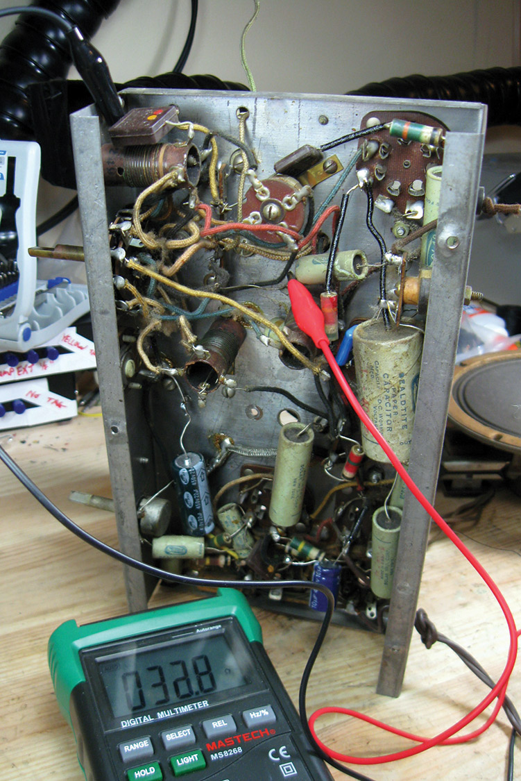
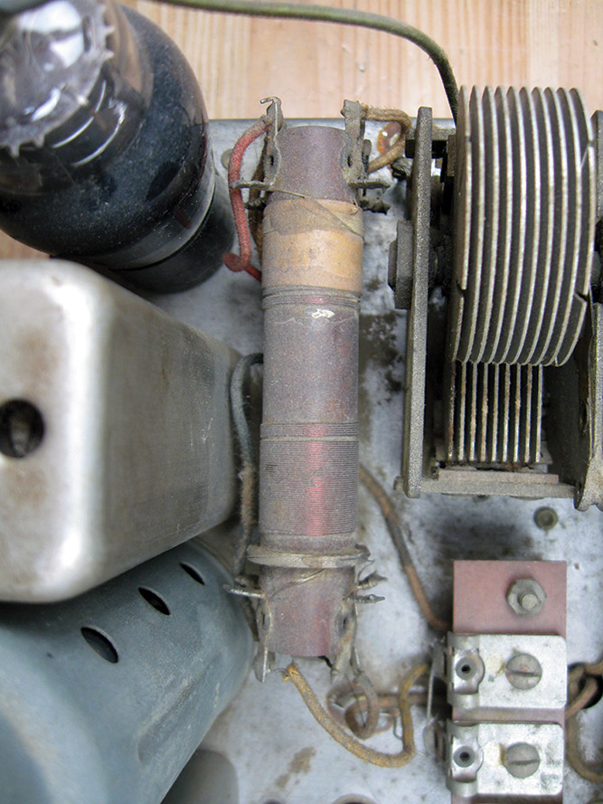
Moving on, since this is a transformerless AC/DC radio, the only items left to check are the filter choke, the output transformer, and the field coil. The filter choke sits on top of the chassis, with the leads heading towards the power supply section. There's only one winding, and the approximate DC resistance is given on the schematic. These tended to have a ±20% tolerance, so the reading of 345 ohms isn't indicative of any problems.
The filter choke.
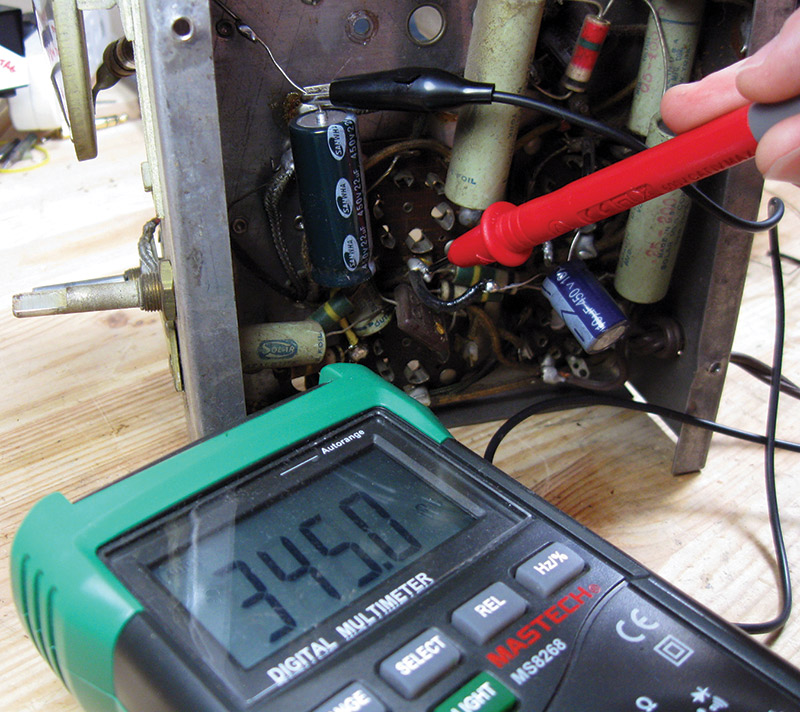
Measuring the filter choke from the bottom, showing 345 ohms.
The other two components — the field coil and the output transformer — are mounted to the speaker itself.
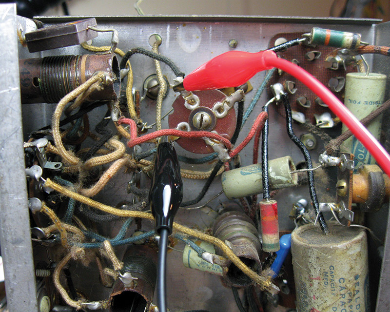
Good permanent magnets which could be used for speakers weren't really found in consumer radios until after WW2, so this radio used an electromagnet to set up the magnetic field and energize the speaker known as the field coil. It's also used in the power supply circuit as a choke, and measuring across the field coil shows 2,309 ohms.
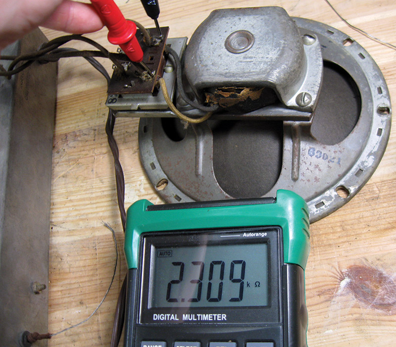
Checking the speaker field coil resistance; 2,309 ohms.
There's no reading given on the schematic, but generally 1.5-3K ohms is reasonable for a 1930’s radio like this one. Finally, the output transformer is also mounted to the top, with the two sharing a common lug. The primary came in at 472 ohms DC resistance, which is pretty typical. The secondary is connected to the speaker voice coil and showed 2.1 ohms.
You might have noticed I didn't test the tubes. If you have access to a tube tester, it's fairly easy to check them out. Unless you plan to repair a lot of tube radios, a tube tester isn't a necessary investment, and you can check their function later with a few simple tests after the first power-up. If you're working on a series-string radio like this one, though, it can be useful to check out their heaters to make sure the radio will at least light up when you power it on for the first time after service.
Tube pinout diagrams can be easily found by searching for the tube's letters and the word "tube" on the Internet, like "6d6 tube." This radio uses all "old style" tubes, though, and on all old style tubes the two pins which are larger than the others and are adjacent to each other are always the heaters. If there's a measurement between those two pins, the tube heater is intact, and the heater string will light up when powered on.
Conclusion and Next Steps
These checks took me about an hour to complete, although if you're starting out on one of your first tube radios to repair, it could take quite a bit longer.
At the end of all my checks, it turns out this radio is in great shape! All the antenna, oscillator, and IF coils tested good, as did the output transformer, field coil, and filter choke. Not too bad at all!
Top of the chassis, ready for work!
If some of those parts don't check out on your radio, not to worry. While you can't pick these parts up in your local RadioShack anymore, there are a lot of options for finding an old stock or a new functional replacement. Consult the Antique Radio Forum for some crowdsourced help if you run into trouble or need a part because someone will almost certainly have one.
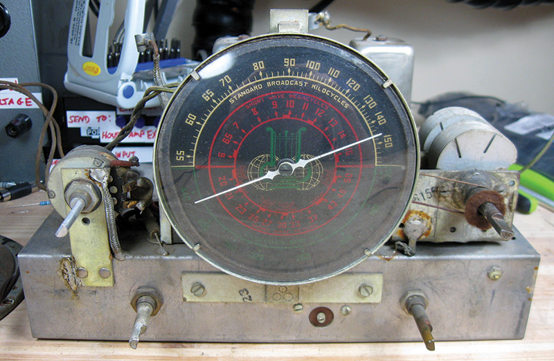
What a neat looking multicolored dial face on this DeWald!
Coming up, I'll be completing the under-chassis component replacement as needed, powering up for the first time to see what happens, and correcting any issues that crop up followed by an alignment. Go find yourself a vintage radio and play along! NV
Special thanks to Antique Radio Forum members Art Hoch, bobwilson1977, chaz, chrisc, db gain, Dutch Rabbit, Flinx, Gary Tayman, Indiana Radios, mrlee, phinegan, RobertL, sgrath92, simplex1040, TexMax, Tim Tress, transister and Zbing who contributed photos and thoughts while brainstorming for red flags you might encounter while exploring a "new" radio for the first time, and to my dad Joe who supplied the DeWald radio used in this project from his collection.