Clocking the Cosmos for Less Than $20.00
The speed of light is the fastest thing there is. Most people know that light travels at around 186,000 miles per second in a vacuum, but that speed is really incomprehensible. Compare it to a rocket that only needs to reach seven miles per second to escape from the Earth’s gravity. To use a more common unit of measure, light travels at 670 million miles per hour; light travels just about one foot in one nanosecond (a billionth of a second). That’s pretty quick. This project will allow you to measure the speed of light simply and inexpensively, as the basic parts cost well under $20.00. However, you will need a good oscilloscope.
The Basics
There are a number of ways to measure the speed of light, and our approach here was chosen for a number of reasons. The first requirement was to use visible light. This makes optical alignment much easier. Besides, it only seems proper to be able to see what you are measuring. A second consideration was the need to keep it simple and small. The “optical bench” is only 12 inches square. The transmitter uses only a single integrated circuit (IC) and the receiver uses only two ICs. The third requirement was to keep it inexpensive. If you buy all new parts, the cost should be under $20.00. Most of my parts came from my junk box, so the cost was much less. A good oscilloscope will be needed; the bandwidth should be greater than 100 MHz for good results (mine was 300 MHz). The design goal is one nanosecond (ns) of resolution (not accuracy). Lastly, this approach will introduce you to a number of optical principles and characteristics.
Fundamentally, the idea is very simple. A clock creates regular pulses. A pulse is used to create a laser light pulse that is sent away from the apparatus and then reflected back. This causes the returned pulse to be delayed very slightly. If we “subtract” the original pulse from the delayed pulse, we will get a short pulse that is due only to the delay. This delay corresponds to the distance the light pulse traveled. Of course, things aren’t quite that easy in practice.
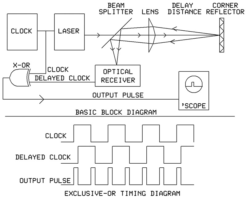
FIGURE 1. It is useful to have crystal stability because jitter on the oscilloscope trace will make it hard to read. This clock drives a semiconductor laser (which is just a cheap laser pointer).
Let’s look at Figure 1. The clock is just a crystal oscillator, and the frequency is not really important. The choice of 4 MHz is fairly arbitrary. It is useful to have crystal stability because jitter on the oscilloscope trace will make it hard to read. This clock drives a semiconductor laser (which is just a cheap laser pointer). We use the laser because it creates a beam of light that’s intense and narrow. The laser pulse travels out and bounces off a corner-reflector.
The corner-reflector is just a red bicycle reflector, but it has the very useful property of reflecting light back from the direction it came from, regardless of the angle. Trying to use an ordinary mirror requires a significant alignment effort (although it could be done that way). Using the corner-reflector is extremely easy, as it will always reflect directly back toward the source. However, this reflection is slightly scattered and is not a tight beam. For that reason, a lens is needed to focus the laser light onto the receiver. This lens is an inexpensive plastic Fresnel lens.
The beam splitter (just a piece of clear plastic) reflects only the returning light from the lens toward the receiver. Otherwise, the receiver would have to be in the same position as the laser. (We’ll discuss the beam splitter and lens in more detail later.) The receiver creates an electrical pulse that is a duplicate of the transmitted pulse, but slightly delayed. These two signals are combined with an exclusive-OR (XOR) gate that “subtracts” one pulse from the other, leaving only those parts that are different. These differences are the results of the distance/delay and are displayed on the oscilloscope.
The Transmitter
Figure 2 shows the schematic diagram of the laser pulse generator or transmitter.
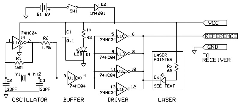
FIGURE 2. This is the schematic diagram of the laser pulse generator or transmitter.
As you can see, it’s very simple. The first section of a complementary metal-oxide semiconductor (CMOS) inverter is used as a crystal oscillator. A second section is used to buffer the oscillator, and the last four sections are used in parallel for increased power to drive the laser diode. The rectifier diode, D2, does double duty. It prevents problems if the power is reversed, and it drops the six volts to about 5.3 volts so the inverter won’t get upset. Resister R3 and LED D1 are optional and are used as a power-on indicator. (It’s just a habit of mine to include them.)
There are a few notes. The inverter can be almost any CMOS family (74H04, 74HC04, 74HCT04, etc.), but bipolar inverters won’t work (7404, 74LS04, 74S04). You can certainly use a commercial oscillator instead of the crystal oscillator circuit. (In that case, you can eliminate R1, R2, C2, C3, and Y1. Connect your oscillator output to U1 Pin 3, and ground U1 Pin 1.) While the oscillator circuit is very robust and will work with nearly any crystal, keep the value around 4 MHz to match the receiver delay circuit (to be discussed later). A 3.57-MHz color-burst crystal should be fine.
Photo 1 shows the transmitter and some parts that require “field modification.” I put the transmitter in a box because I have a feeling that I will find a number of uses for a laser transmitter that can be modulated at up to 20 MHz. As you can see, the actual electronics fits on a small, perforated circuit board, and point-to-point wiring was used.
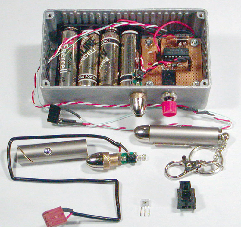
PHOTO 1. This is the transmitter and some parts that require “field modification.”
The laser I used was a key-chain type that used three 1.5-volt button batteries (right center of Photo 1). I chose to remove the laser head from the body for ease of use. (You don’t have to, but you will have to make power connections somehow.) I carefully used a hacksaw to remove the head assembly. You can see the spiral cut in the body (left center). The laser head consists of a lens, laser, and a tiny PC board (center). I attached power wires that bypassed the switch so I wouldn’t have to press the button for the laser to work. The long leads were only for testing. (The two parts in the lower right of Photo 1 are the optical receiver and will be discussed later.)
The laser key chain I had on hand was very convenient. It worked on 4.5 volts, so a 5.3-volt, 50 percent duty-cycle signal didn’t overload it.
There was no actual driver circuit for the laser. There was only a 62-ohm surface-mount resistor that limited current. This meant that I could drive it with a very fast signal without problems. A good laser pointer with a real current control circuit probably won’t be able to handle the high-speed signals. If you use a laser that runs on three volts (or other voltage), be sure to use a suitable current-limiting resistor. My oscillator circuit used an additional 14 mA with the laser on. This means that the peak current was 28 mA (50 percent duty cycle). Since most of the red laser diodes are very similar, a 62- to 75-ohm current-limiting resistor supplying about 25 mA DC should be okay for a pulsed 5.3-volt operation. Also, the head assembly acts as a heatsink. It is critical that the heatsink be functional; otherwise, the laser will quickly overheat and destroy itself.
The Optical Bench
When you work with optics, it’s important to be able to keep components stable and fixed. It’s also important to be able to remove a component and then replace it easily. The tool used for this is called an optical bench. A professional optical bench is typically made of metal, about two by three feet, and has holes every inch (sort of like large perf-board). Optical component carriers hold the optical elements, while the base of the carrier plugs into one or more holes in the bench. Optical benches can cost $1,000.00 or more. That’s a little pricey for us, so we will create a single-use optical bench out of wood.
There are many approaches to building the bench. I’ll explain how and why I built mine the way I did. (Feel free to choose the methods that you feel most comfortable with.) Photo 2 shows the basic layout. The base is a 12 x 12-inch piece of particle board. The transmitter case is snugly held in place with pieces of 3/4 x 1-inch wood screwed to the base. The beam splitter rests in a slot I cut out of a scrap of 2 x 3/4-inch wood. The wood is also screwed to the base. I used shims cut from a business card to keep the plastic snug in the slot.
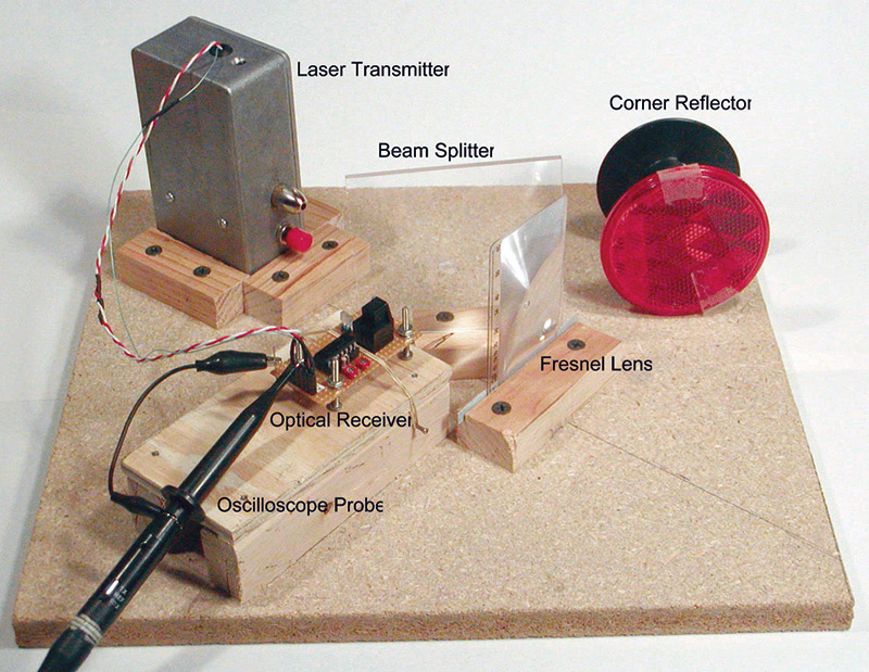
PHOTO 2. The basic layout. The base is a 12 x 12-inch piece of particle board.
A similar procedure is used for the Fresnel lens. The optical receiver PC board is raised to the approximate height with a wooden base. For fine tuning of the height, I used long screws as feet. By adjusting the screws, I could position the receiver with precision. The receiver was held in place with high-tech, one-dimensional organic tension straps (otherwise known as rubberbands). The corner-reflector shown in Photo 2 is just taped to an empty reel of wire to keep it vertical. In actual use, it is not part of the bench assembly and is placed several feet away.
There are a few things to discuss about the beam splitter and the Fresnel lens. The beam splitter is just a scrap piece of clear plastic. It’s about 4 x 4 x 1/8-inch thick. Any piece of clear plastic should be okay. Its distance from the laser and the mounting angle are not too important. Give yourself room for the other components. (I guessed, not measured, around 45 degrees.) You can use glass for your beam splitter, but, obviously, glass is sharp and fragile. Additionally, it’s hard to drill a hole in glass. There is a hole in the center of the beam splitter, but it’s very hard to see in the photo. It’s not absolutely necessary to have the hole, but it helps. Here’s why: If we split the beam on its outward leg, we lose about 50 percent of the light. Obviously, we want as much light reflected as possible, hence the hole. There is also a hole in the Fresnel lens, but this hole is critical. If the outgoing laser beam passes through the lens, the beam will spread out too much.
The Fresnel lens I used was a credit card magnifier (or “wallet” magnifier) that was a free promotional item I got from some company years ago. Its placement isn’t too critical. Just remember that the focal length is about 3.5 inches (yours might be different). Therefore, the distance from the lens to the beam splitter to the optical receiver IC will be that length. The important thing is to make sure that the parts don’t interfere with each other.
The easiest way to find the precise location for the holes in the beam splitter and lens is to fix the components on the bench and turn on the transmitter. It is easy to see where the light passes through the plastic and lens. Mark that spot and drill an 1/8-inch hole. You may have to enlarge it slightly to allow the whole beam to pass through, but don’t make it any larger than necessary. You lose this area when the reflected beam comes back. Since the beam splitter is mounted at a 45-degree angle to the laser beam, the hole should also be at 45 degrees. Otherwise, the beam will hit the edges of the hole. This should be done after the initial hole has been drilled. If you used a hand drill, secure the plastic in a vise with the drill through the hole. Then carefully start the drill and slowly move the drill to the proper angle. The edge of the bit will cut/melt the plastic. If you used a drill press, start it up before you manually twist the plastic. Use gloves or a drill press vise to hold the plastic for safety.
The Receiver
After a couple of attempts to build a simple, low-cost, high-speed optical receiver that resulted in marginal success, I decided to use the Sharp GP1FA551RZ fiber-optic receiver. It’s very cheap — under $2.50. It’s simple to use — three pins. Also, it’s fast, with a response of 13.2 MHz. Figure 3 shows the circuit, but the actual receiver circuit is trivial.
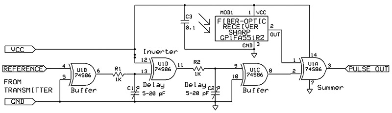
FIGURE 3. This is the circuit of the Sharp GP1FA551RZ fiber-optic receiver. For under $2.50 it is fast, with a response of 13.2 MHz.
Connect the Sharp IC to power and ground and run the output to the XOR. Bypass capacitor C3 is required (placed at the receiver IC), as the circuit will oscillate without it.
What’s with the other three gates, though? What are they there for? They’re not in the block diagram. These gates are needed to invert and delay the reference signal to compensate for the delays in the laser and receiver. We want to measure only the time it takes light to exit the laser and return. Unfortunately, all electronic components require some time to operate. There are a few nanoseconds (ns) of delay from when power is applied to the laser and when light is emitted. There is also a delay from when light strikes the photo diode in the receiver to when a signal is available at the output pin. Surprisingly, the receiver has a worst case delay of 180 ns. This is very large. The good news is that the jitter — or delay variability — is typically only one ns. Since 13.2 MHz corresponds to a wavelength of about 57 ns, I figured that a realistic “typical delay” estimate should be no longer than that (for a strong signal). Therefore, I chose to design the delay circuit for about 60 ns. (Note, you can choose not to use delay compensation. In that case, all your measurements will be off by a fixed amount. You can subtract this amount manually to find the speed of light, but it’s not very elegant.)
Let’s step through the circuit. First, you must use a Schottky 74S86 (not the 7486 or the 74LS86). The 74S86 has a symmetrical, 10-ns, low-to-high and high-to-low delay. Of course, the other families have different propagation delays. Remember, we want to resolve one ns. The first thing we do is buffer the reference signal. The XOR with one input connected to ground does this. Then we delay the signal with R1 and C1. This provides about five to 20 ns of delay. Then, the signal is inverted by connecting an input to a logic high. Next, we delay this by five to 20 ns with R2 and C2. Finally, the signal is buffered again with the last section of the XOR chip. The delay is 30 ns for the three XOR sections and 10 to 40 ns for the delay circuits for a total delay of 40 to 70 ns.
There are some subtle points to note. Two resistor-capacitor (RC) delay circuits are used because the XOR output has asymmetrical drive. It sinks much more current than it can source. This means that the capacitors will discharge faster than they charge. If only a single RC delay was used, the rising edge would be delayed more than the falling edge. By using two RC delays — one on an inverted signal and the other on a non-inverted signal — we can control the delay of each edge and can make the delays symmetrical. (Note, if your receiver has a significantly different delay, you may have to adjust the values of the RC circuits. For more delay, increase the resistor and/or the capacitor values, and for less delay, reduce them.)
The other point is a very useful property of the XOR gate. A logic low at one input means the output follows the other input. A logic high at one input will invert the signal at the other input. This means that you can control the inversion (or phase) of a signal with a logical value without changing the propagation delay. If you do a lot of digital design, you will find this little trick valuable.
Unfortunately, there is a problem with the receiver. The actual IC is a small three-pin device buried in a large plastic housing, which is normally mated with a fiber optic cable. It’s very difficult to align the laser light to shine deep into the small hole used for the cable. While that is possible, it’s much easier to remove the IC from the housing. I know because I tried it both ways. Look closely at Photo 2. At the front is a large, black component. That’s the optical receiver. If you look to its immediate left, you will see a small, clear, plastic object. That’s the actual receiver IC that has been removed from the housing. A better picture of the receiver and housing is shown at the bottom right in Photo 1.
I was successful in removing the receiver IC with two different methods. The first, shown in Photo 1, was to very carefully saw the sides of the housing until I reached the cavity that held the actual IC. However, once I did that and was able to examine the inside of the housing, I noticed that two small retention barbs held the IC in place. These barbs are accessible where the IC leads exit the cavity. The next time, I used an X-acto razor knife to cut these barbs away. With a little inward pressure on the face of the IC through the hole (using a toothpick) and gentle pull on the leads, the IC was removed.
Setup and Operation
Physically adjust the transmitter, beam splitter, and lens position so that the beam of light passes through the holes. Then place the corner-reflector about five to 10 feet from the bench. While, in theory, the corner-reflector can be at any angle to the beam, it’s best if the laser light hits it head on. This will reflect light back and through the lens and beam splitter. A white card or piece of paper will show where the beam is focusing into a point. This is precisely where the optical receiver IC must be located. (Note that you will probably see two closely-spaced points of light. This is because the light reflects from both the front and back surfaces of the beam splitter. With 1/8-inch-thick plastic, the two points will be about 1/8-inch apart. Thinner plastic brings the points closer together.)
Once the optical alignment is complete, connect the high-speed oscilloscope to Pin 3 of the 74S86 (summed output). (I used an oscilloscope with a 300 MHz bandwidth.) In Photo 2, you can see that I brought this out to a test point. Connect the probe as close to the chip as possible and do not use a cable or a long length of wire. Remember, we want to measure nanosecond signals. You should use a 10X probe for better signal response. With the corner-reflector removed, you should see the “clock” signal, as shown in Figure 1. With the corner-reflector in place, you should see the signal change to the “output pulse” form (also shown in Figure 1). You may want to fine tune the optical alignment with the oscilloscope. A good alignment is indicated by a stable signal with the narrowest pulse width (more on that later).
In order to adjust the delay circuits properly, we need to reflect the beam right back from the face of the lens. Unfortunately, it’s difficult to do this because the beam is very narrow at that point and reflects back through the holes in the lens and beam splitter without reflecting onto the receiver IC. I “cheated” a little by reflecting some of the beam just as it came out of the laser directly onto the IC. This distance “error” is about six inches (or about 0.5 ns) and I felt that it was insignificant.
With a direct signal into the receiver circuit, adjust the capacitors so that the output pulses narrow and disappear. At this point, the delay from the delay circuit exactly equals the delays from the laser and receiver. (You may have to fiddle with the delay-component values as previously mentioned. However, my receiver worked well without any component adjustments.) Now, we’re ready to actually measure the speed of light.
Results
Photo 3 shows a typical output pulse with a 300-MHz ‘scope. Photo 4 shows that same pulse with the bandwidth limited to 20 MHz.
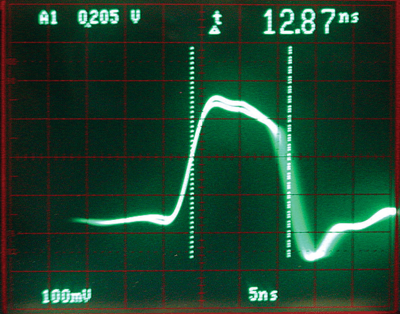
PHOTO 3. This is a typical output pulse with a 300-MHz ‘scope.
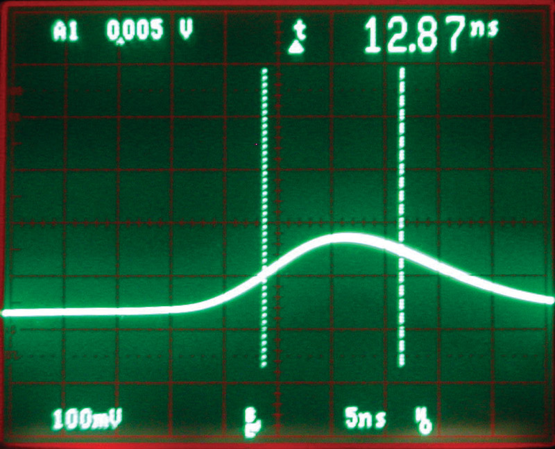
PHOTO 4. This shows that same pulse as in Photo 3, but with the bandwidth limited to 20 MHz.
As you can see, you will need a 100-MHz bandwidth for reasonable results. The corner-reflector was placed 10, 15, and 20 feet from the optical bench. This means that the actual travel distance was twice that (out and back). Here’s what I measured:
| Distance |
Delay |
Measured speed |
Error |
| 20 feet |
15.2 ns |
249,000 miles/s |
+34% |
| 30 feet |
27.2 ns |
208,000 miles/s |
+9% |
| 40 feet |
42.4 ns |
183,000 miles/s |
-1.7% |
Okay, so the results aren’t all that accurate, but — for $20.00 worth of parts — it isn’t that bad. I suspect that much of the problem lies with the receiver delay. I would be very surprised if the light intensity didn’t have a significant effect on its delay (which is why I adjusted the optics for the shortest pulse). This is evidence that the intensity changes the delay. I didn’t measure this. (However, you can do this by keeping the corner-reflector at a fixed distance and changing the laser intensity with an optical filter. This will provide “first order” compensation values that can be used to correct the readings.)
There are a number of variations to the design that are possible. As mentioned before, a mirror can be used instead of the corner-reflector. In that case, the beam splitter and lens may not be required (although a lens may still be helpful). You can measure the speed of light in water by submerging the corner-reflector in a swimming pool. You can always redesign the receiver using discrete components for better delay characteristics.
Use your imagination. NV
PARTS LIST.
| Transmitter |
| R1 |
10M |
1/4 W |
| R2 |
1.5K |
1/4 W |
| R3 |
1K |
1/4 W |
| Rx |
Part of laser pointer (see text note) |
| C1 |
0.1 µF |
25 V |
| C2, C3 |
33 pF |
25 V |
| D1 |
Red LED |
| D2 |
1N4001 |
| Dx |
Key chain laser pointer (see below) |
| Y1 |
4 MHz crystal |
| SW1 |
SPST switch |
| U1 |
74HC04 hex inverter |
| Note: There are many sources for these inexpensive lasers. I’m quite sure I got mine from All Electronics a few years ago. Officedepot item 783351 appears to be similar. |
| Receiver |
| R1, R2 |
1K 1/4 W |
| C1, C2 |
5-20 pF variable cap |
| C3 |
0.1 mF 25V |
| U1 |
74S86 Schottky Exclusive OR Do not substitute. |
| MOD1 |
GP1FA551RZ Sharp fiber-optic receiver IC (13.2 MHz speed) |
| Optical Bench |
| Beam-splitter |
4” x 4” x 1/8” clear plastic (see text) |
| Lens |
Credit card/wallet Fresnel lens magnifier 2” x 4 (approximately) |
| Edmund Scientifics and Officedepot have lens magnifiers that might be useable. A web search brings up many other listings. |
| Misc. |
12” x 12” wood base, small wood strips to mount parts, screws, etc. |