The first signal that sputters through the ether, past your mess of wires, into your ears, and out of your hand into space, is stuff of subliminal beauty that is the pleasure of the home-brewer alone.
Ashhar Farhan
Rarely has there been as much interest in a high frequency radio as that shown to the Microbitx. Low power enthusiasts — better known as QRP operators as well as ham radio hobbyists — have rushed to place their order for this exciting and challenging new transceiver kit.
Introduction
Ashhar Farhan VU2ESE — the polymath from Hyderabad, India — whose Bitx series of transceivers has taken ham radio’s QRP world by storm, is following his recent Bitx40 success by offering the impressive Microbitx transceiver, also known in ham radio circles as the Ubitx (which we’ll refer to it as here).
Having recently introduced the Ubitx to an eager market, Farhan has been struggling to keep up with the high demand for his new radio while receiving reports from many users that Ubitx’s audio chips are failing — some of them failing in spectacular fashion (Figures 1 and 2).

FIGURE 1. Blown audio chip from a MicroBitx transceiver.
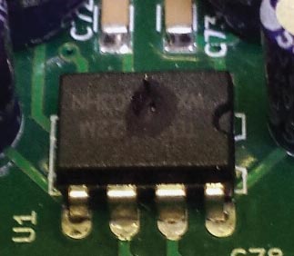
FIGURE 2. Another blown audio chip.
True to form, Farhan has wasted no time in addressing the problem, but as of this writing he’s been unable to nail down the exact cause of the chip’s failure. He’s also not able to say how many of the defective chips have made their way into the user community.
Apparently, the defective chips are from a series marked “WX.” Farhan is advising all users who have chips from the WX series to replace them with a chip which is known to work. Several users have replaced the defective chip with the JRC 2073D, and others have used the very reliable LM386. Be advised, however, that the LM386 is not pin-compatible with Ubitx’s chip and will require an interface to be used.
Additional fixes for the audio chip problem can be found on Ubitx.net but most of them require somewhat complex modifications to the main board.
Unfortunately, Farhan’s decision not to use chip sockets and instead solder the chips directly to the board has unnecessarily complicated the repair.
Farhan stated on his website that the Ubitx boards were thoroughly tested prior to being shipped. Still, the defective chip made its way onto some of the Ubitx transceivers and is causing difficulty for the users who bought them.
A more detailed explanation of the failing audio chip can be found on the website. Sadly, the failing audio chip is a black mark on what is otherwise a well-built and effective transceiver.
About the Ubitx
Technically, Ubitx is very well designed. It’s an all-band, computer controlled, and menu-driven transceiver, which will operate in either voice (SSB) or Morse Code (CW) modes. Ubitx puts out between seven and 10 watts of power on the 40- and 80-meter bands, and from two to five watts on 20 meters and above.
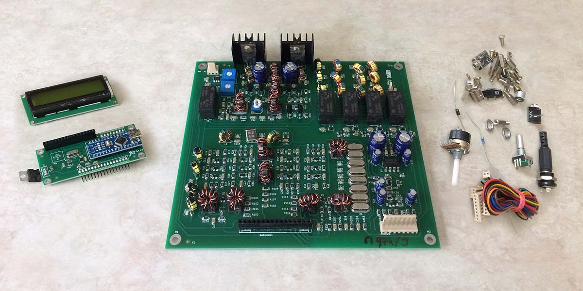
Similar to the Bitx40, the Ubix is sold as a kit (Figure 3) at the very reasonable price of $129 which includes shipping, making it one of the most affordable all-band transceivers in today’s market.
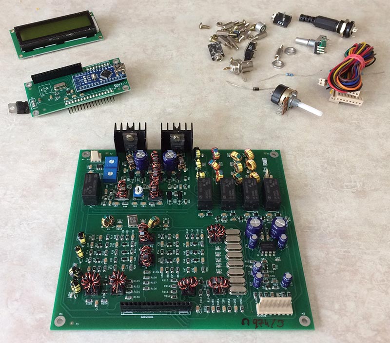
FIGURE 3. Microbitx kit prior to assembly.
(Shipping for Ubitx is free, but Indian Post is known to be exceedingly slow. For an additional $10, the kit will be shipped by DHL which can deliver it within 10 days of your order. Unfortunately, due to the unexpectedly heavy demand, shipping on all Ubitx transceivers has been delayed several weeks.)
Farhan does not provide technical support of any kind. Instead, users who require assistance are referred to the Ubitx user community for support. The two primary sites where support can be found are Ubitx.net and groups.io/g/BITX20.
All information about Ubitx is “open source.” Every schematic, every line of code, and every page of documentation are provided to the user. Farhan has often referred to the Bitx series as experimental and has invited users to put their own ideas into action.
Tinkerers and hackers are welcomed, as well as any user who desires to build or modify the Ubitx.
Farhan believes that by referring the Ubitx users to the general user community for support, everyone will benefit from the combined knowledge and experience of the world’s most competent Bitx users.
On the Technical Side
Ubitx is a state-of-the-art design (Figure 4), with economy playing a role in each decision. Farhan has sought throughout Ubitx’s design to balance cost with reliability.
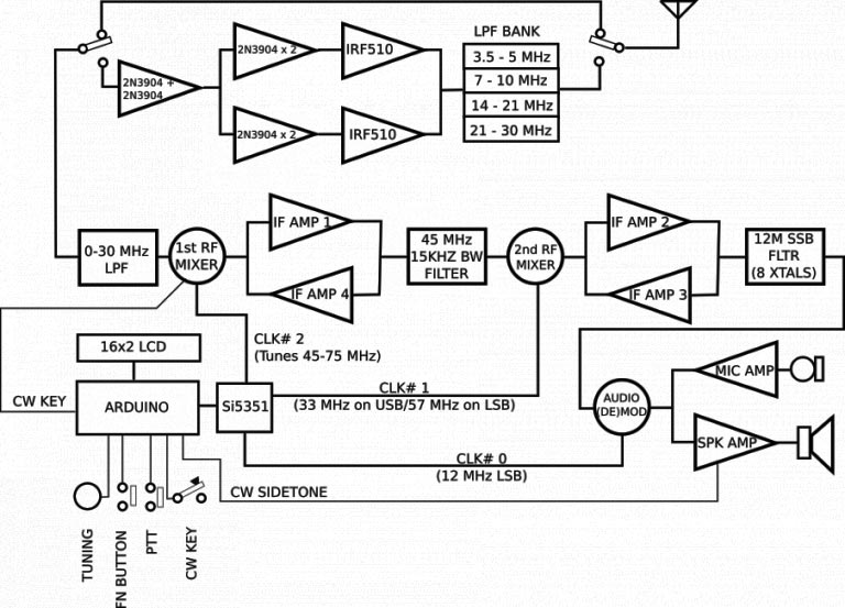
FIGURE 4. Block diagram of the Microbitx transceiver.
The control center for Ubitx is the Arduino Nano microcomputer which is coupled with an Si5351 frequency generator.
Farhan has named this combination of devices “the Raduino.” Generic firmware for the Raduino comes preinstalled, and more enhanced versions can be found on user websites.
The Silicon Labs’ SI5351 frequency generator has greatly reduced the complexity associated with building multiple band transceivers.
By including just one 25 MHz crystal to serve as the frequency reference, the SI5351 can digitally generate oscillations in the range of 8 kHz to 160 MHz. To paraphrase Farhan, the SI5351 has reduced the complexity of multiband transceivers to a relatively trivial matter.
Neither Ubitx nor its predecessor (the Bitx40) would have been possible at their low price were it not for the Si5351.
The Ubitx uses an up-conversion, double superhet design (Figure 5) to the first intermediate frequency of 45 MHz, eliminating the need for large band-pass filters. At 45 MHz, the roofing filter is 15 kHz wide.

FIGURE 5. Up-conversion schematic for the Microbitx transceiver.
The signal is down-converted to 12 MHz where an eight-crystal filter (Figure 6) is used for both CW and SSB. The eight-pole filter in the second intermediate frequency is 2.3 kHz wide.
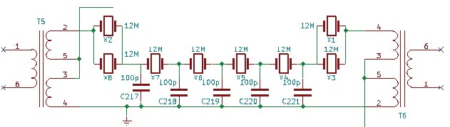
FIGURE 6. Eight-pole filter schematic for the Microbitx.
The receiver front end has a 0-30 MHz low-pass filter which is used to keep out signals from FM broadcast stations; refer to Figure 7. This design utilizes a doubly balanced diode mixer which is made up of two matched Bat54SL diodes. No amp is required here because sensitivity at this point is adequate.
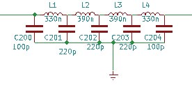
FIGURE 7. Schematic for the Microbitx low-pass filter.
Ubitx uses four intermediate frequency amplifiers which don’t require transformers; each one has a gain of 16 dB.
Generic 2N3904 transistors are used throughout the transceiver with four 2N3904s serving as push/pull drivers to the finals section which uses inexpensive IRF510 field-effect transistors.
Following the finals are four filters which are in place to prevent harmonic distortion on the output signal.
Operator Interface
Another feature of the Ubitx which is not usually found in low power radios is the comprehensive and well-conceived operator interface. Ubitx operators can access a host of menu options simply by depressing the tuning encoder. These options include a receive incremental tuning (RIT), dual variable frequency oscillators, a CW keyer, calibration, and many others. Most of the menu options have logical defaults which are easily overridden.
To enter CW mode from single side-band mode, the operator need only press his CW key. The Raduino will return to SSB mode when it senses that the operator has stopped keying.
The Ubitx kit comes with a completely built and tested main board, Raduino, and all the peripherals and parts. It doesn’t include a speaker, a power supply, or an enclosure.
Building the Transceiver
Instructions for building the Ubitx transceiver are found on Hfsigs.com. A note to new builders: The Ubitx build does require soldering. Some prior experience with kit building and schematic reading will be very helpful. Ubitx can be assembled by following the wiring diagrams shown in Figures 8 and 9. Or, if the builder prefers, Farhan has placed more detailed instructions on his website.
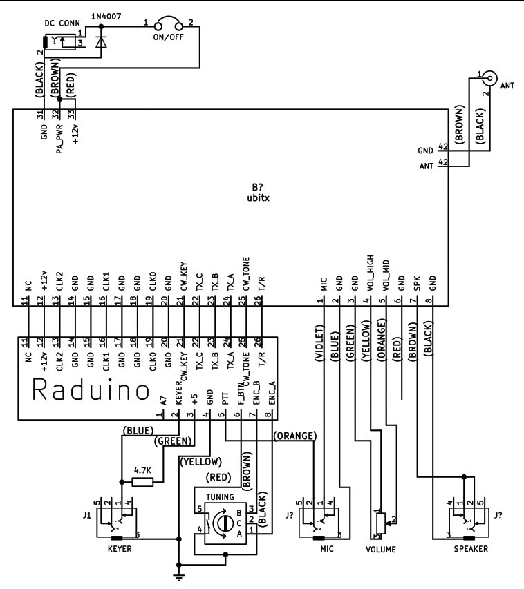
FIGURE 8. Farhan’s wiring diagram for the Microbitx.
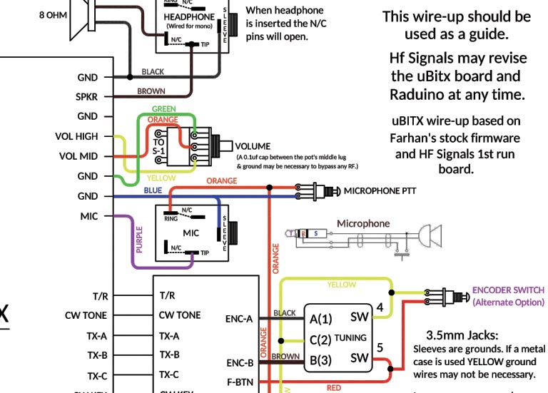
FIGURE 9. Another wiring diagram for the Microbitx from Wiki build.
As you build Ubitx, be very careful that the main board doesn’t get exposed to static electricity. Even the smallest charge of static electricity can destroy a board’s circuitry.
Included with the kit is a 1N4007 diode which is to be connected across the power connector to prevent damage from short circuits and other spikes in power. Unfortunately, the 1N4007 diode doesn’t provide adequate protection. Every builder should place a two-amp fast blow fuse in the positive line of the power supply. It’s much better to take the time to add a fuse than to stand by helplessly while your printed circuit board burns.
The code keyer must be connected, even if you don’t plan to use the Ubitx for Morse Code.
I used an on/off toggle switch for my PTT (push to talk) switch, but a standard microphone can be added if desired. There are plenty of schematics online which show how a hand microphone can be connected to a Ubitx.
The microphone, CW keyer, and speaker are connected to the Ubitx through three 3.5 mm sockets which are included with the kit.
Building My Enclosure
As I’ve done with past projects, I fabricated my enclosure from a thin metal box which was once used as a cookie tin. I like using this type of enclosure because they’re inexpensive and plentiful, and can be found in many different shapes and sizes.
Perhaps the best feature of using this type of material is that a nice enclosure can be fabricated by using common hand tools. Learning how to build an enclosure from thin gauge metal has at times been tricky business, but over the years, I’ve acquired a few techniques that work well.
The most difficult task in fabricating an enclosure from a thin metal box is cutting the opening for the 16x2 mm LCD. I like to begin by carefully marking the spot for the LCD opening and then scoring it with a sharp edge. Once the opening is marked and scored, I drill four relief holes; one on the inside of each corner. The relief holes will stop me from cutting beyond the mark. I use a rotary tool with a cutting disc to cut the opening.
Openings for the encoder, volume control, and other parts are relatively easy to cut. I prefer to cut these types of openings with a hand drill, but some builders have been successful using a metal punch.
When laying out the enclosure, it’s best to place the openings for the power and antenna connector in the rear panel of the box. The openings for the keyer, speaker, PTT, microphone, and volume control should be placed on the front panel of the box.
Once cutting and drilling are completed, I lightly sand the box and follow that by applying a coat of automotive primer. Any primer will likely work, but I’ve found that paint will adhere to automotive primer quite well. Once the primer has dried, I paint my enclosure with a lightly textured paint which is very good at covering scratches on the metal.
The Moment of Truth
I’d built a nice enclosure and completed the Ubitx assembly. The time had now come to test my unit (Figure 10). Like many hobbyists, I’ve often used the term “smoke test” in a joking manner, but with the Ubitx audio chips overheating and exploding, that phrase didn’t seem quite as funny as it once did. It was now time to find out if the audio chip on my Ubitx was going to work.
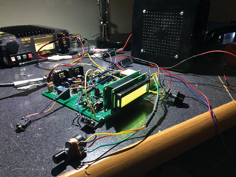
FIGURE 10. Microbitx transceiver ready for testing.
I made one more scan of the wiring to ensure each part was correctly connected and switched on 13.8 volts of the power.
To my satisfaction and relief, my Ubitx powered up without blowing the audio chip. As I listened, however, the audio began to degrade and show signs of distortion. After operating for a few minutes, the audio became too distorted to be understood.
I performed the tuning procedure described on Hfsigs.com and it’s here that I realized my audio chip wasn’t working. No matter how I tried, I couldn’t tune my Ubitx to a point where the audio was distortion-free. The audio appeared to be better when my Ubitx first powered up, but soon, even those few moments of audio clarity disappeared, and it was impossible to understand SSB audio. My audio chip had failed like the ones being reported on the forums.
Replacing the Bad Audio Chip
The defective audio chip was in a hard to get to spot and somewhat challenging to remove. As I replaced the defective chip with the JRC2073D, I made sure to use a chip socket, so should the new chip have to be replaced, the task of changing it will be much simpler than it was the first time around.
There are a couple ways to remove the defective chip. I did it by clipping the pins of the chip from the top and then removing each pin one at a time. As I replaced the defective chip, I made certain to wear my grounding strap to prevent damaging the main board with static electricity.
Once the JRC2073D chip was installed, the Ubitx really came to life. Its audio is now crystal clear with practically zero distortion. Now, my Ubitx sounds the way it was meant to sound.
I’ve yet to make any contacts while using the new audio chip but prior to the old chip going bad, I made several contacts with one of them being almost 700 miles from my station. While testing with the new audio chip, the Ubitx put out the advertised 10 watts of power on 40-meter SSB.
My Ubitx is assembled and working very well! You can see it in Figure 11.
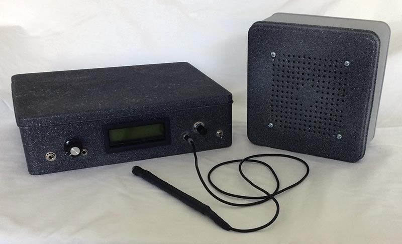
FIGURE 11. My Microbitx transceiver with enclosure and speaker.
Final Thoughts
While I’m hesitant to end on a negative note, I do have some concerns about Farhan’s philosophy of support.
As it currently stands, every problem, question, or support issue of any kind is referred to the user community on the Internet. The problem with the audio chip is a good example. Builders on several forums have suggested hardware modifications to the main board to remedy the failing chip. I feel certain these builders have the best of intentions, but how can a user who needs to make these modifications have any confidence that the proposed changes are feasible?
I recently read an exchange on a forum where a Ubitx builder posted a question regarding tuning. The fellow who answered his post suggested that the way to resolve the tuning issue was to reinstall the firmware on the Raduino. Perhaps reinstalling the firmware was the correct answer but changing the firmware to address a tuning issue appears — at first thought — to be a bit extreme. Again, how can the user have any confidence that this will work?
I was told of another incident on a forum where a builder was heavily criticized by forum members when they mistook his question to be personal criticism of Farhan.
Of course, none of these concerns would matter very much if Farhan’s target market consisted of only engineers and technicians who possess the technical experience and ability to modify the Ubitx as needed.
However, Farhan has stated that one of his primary goals is to use the Bitx series of radios to bring amateur radio to potential users who don’t have a technical background or who lack access to other sources of support. With these users in mind, I question whether the support offered is comprehensive and reliable enough.
As a big fan of Farhan and the entire Bitx series of radios, I view this lack of direct support as a weakness in an otherwise great product.
No one wants to see the price of these radios increase, but it seems at the very least, one specific website should be maintained which can serve as a central repository of information where builders can visit and have confidence that their questions and problems will be addressed correctly.
Despite the early problems, Ubitx is an excellent transceiver which has brought a much-needed jolt of excitement to the world of low power ham radio. Ubitx is a worthy addition to the Bitx family, as well as to the ham radio hobby.
Farhan and company should be very proud of Ubitx, and as hobbyists and builders, we should all be happy that we get to participate in the evolution of a radio that is sure to last for many years to come. NV