Microcontrollers are great, especially those on the market today. They let you easily control devices and gather input from others with simple programs and circuits. However, not every application needs one, yet oftentimes they're used in a project unnecessarily. For instance, micros are often used to accomplish such simple tasks as blinking an LED. While this may be a fine thing to do with a microcontroller, it's overkill. It's synonymous to using a table saw to cut a piece a paper when a standard pair of scissors will do the job just fine.
Many beginners to microcontrollers overlook the basics of electronics and don't realize they can accomplish the same goal using conventional methods. Using conventional electronics, as opposed to a micro, you may use a few more resistors and capacitors, but your project will probably end up costing you less. In addition, you won't have to write a program and you'll learn a bit more about the fundamentals of electronics.
I’ll show you two examples of circuits that don't use a micro, but are often built with one. I'll also briefly explain some of the logic and theory behind these circuits. Hopefully, you can incorporate them as they are or — at the very least — they'll give you ideas to build on. These examples can replace the microcontroller in a simple project, but can also be helpful in offloading some of the work your micro would do in a big project.
Lots of Little Lights
Every project needs to have several — if not many — blinking LEDs. Making an LED blink is probably the first thing you did when you learned how to use your microcontroller. Fortunately, it's also easy to do without one. Let's take a look at how to alternately blink two LEDs using just a few components.
Flip-Flops and RC Circuits
There are many different ways that this can be done, but one of the easiest is by using what's called a flip-flop. Flip-flops are regularly used in nearly all digital integrated circuits, including microcontrollers. A flip-flop takes the output state from one logic circuit and feeds it into the input of another. Then, that output feeds into the input of the first circuit. In this way, the output of each logic circuit is dependent upon the other’s previous state. There are many different types of flip-flops. An Internet search will easily find much information on the different types and how they are used.
In addition to the flip-flop, you need a way to trigger it, such as with an RC circuit. On their own, capacitors have limited use and are good for things like filtering A/C voltage (and shocking your friends), but — when used in conjunction with a resistor — they become very useful. Put these two devices together, and you can create an RC circuit.
There are two types of RC circuits: integrators and differentiators. When a voltage is applied to an RC circuit, the capacitor “fills up” with energy. Then, when the voltage is taken away, the resistor “drains” the capacitor. The time it takes to “fill” and “drain” the capacitor can be measured in seconds and is called the RC time constant. Changing the values of either the capacitor or the resistor allows you to adjust this RC time constant. The real difference between the integrator and the differentiator is in the way that the output behaves. These differences are shown in Figure 1.
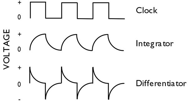
FIGURE 1. Differences between an integrator and a differentiator.
Using the flip-flop and the RC circuit, you can create a basic circuit that will alternately blink two LEDs. I used the RS (RESET–SET) type because it's the most basic flip-flop and it fits my needs perfectly. I used the differentiator RC circuit because it has the best output for triggering digital logic circuits. If you add a few LEDs and more resistors, you'll have a circuit that will alternately blink two LEDs. This circuit is shown in Figure 2.
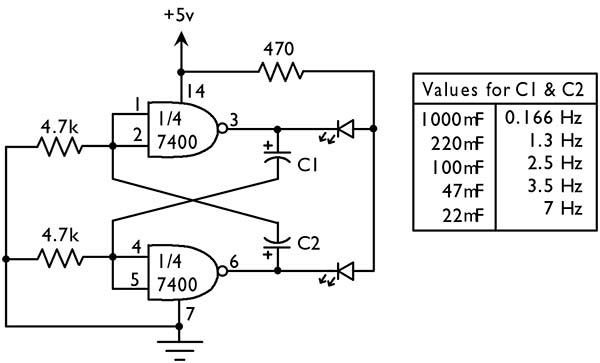
FIGURE 2. Flip-flop circuit that alternately blinks two LEDs.
NAND Gates
The logic circuits I used to create the RS flip-flop are NAND gates. You can learn more about NAND gates, as well as many other basics of digital electronics here. For now, however, it's sufficient to understand that a NAND gate’s output only goes high when its two inputs are low. So, when you first apply power to the circuit (Figure 2), one of the two NAND gates (depending on which one is faster) will set its output high.
This will feed power to the differentiator that is connected to the output of the first NAND gate. This will send a digital “1” to both inputs on the other NAND gate, thus making its output low (turning off the second LED). The first LED will stay lit until the voltage output of the differentiator goes to near zero. At this time, the output of the second NAND gate will go high (turning on the second LED), thus sending the outputs of the first NAND gate to low (turning off the first LED). This process will go on as long as power is applied and nothing in the circuit breaks.
Using the Circuit
To adjust the timing of the blinking LEDs, you can experiment with different values for the two capacitors. Higher values will increase the delay and lower values will decrease the delay. If you want both LEDs to be lit for equal amounts of time, then use the same values for both capacitors. Try different values and see what kinds of results they give. You can also try using different values for your resistors to see what kind of effects they may have.
Building a circuit like this with a microcontroller would hardly require any external parts, but you would have to give up two of your microcontroller’s output pins. In a big project, two pins can be quite costly and, even though you may need a few extra parts, this circuit will save those two pins. If all you need is to alternately blink LEDs (like for a railroad crossing sign for your model train track), then this circuit is perfect for you, and it'll probably only cost you a couple of dollars. Plus, you won’t be putting your microcontroller to sleep.
Temperature Switch
Getting temperature readings is a very common thing for any electronics hobbyist to do. Let's say you have a project in which you want an alarm to sound if your freezer rises above a certain temperature or you may want to know if something gets too hot (like the inside of a case). This can easily be done with a microcontroller, but you can also do the same thing with a few conventional electronic parts.
Temperature Probe
The first thing you need to read a specific temperature is a temperature probe. Temperature probes can usually read a range anywhere from -50°F to over 300°F. Most give an output in voltage that is linearly proportional to the temperature of the probe. These probes are already calibrated and are guaranteed to be accurate. Some read the temperature in Fahrenheit and others in Celsius. The one that I chose to experiment with is the LM34DZ. It can operate on a supply voltage from 5 to 30 volts and measures temperatures from 32°F to 212°F. Each degree of change will alter the output by 10 mV.
The Comparator
The LM34 will output a specific voltage for each degree of temperature. In order to detect a specific voltage from the LM34, you need a comparator. I used the LM339 quad comparator because it's very common and I had one lying around, but you could use any one of many on the market today. The LM339 actually has four comparators onboard, so you can do some fancy stuff with it if you want to, but I only used one of the comparators for my circuit.
A comparator has two inputs and one output. One of the inputs is set as a reference voltage and the other input is the voltage you want to compare with the reference voltage. If the input voltage reaches the reference voltage, it sets the output to high. For instance, let’s say that you want to know when a particular input reaches six volts or more.
In this case, you would set your comparator to non-inverting and your reference voltage to six volts. Then, when your input reaches six volts or more, the comparator will set the output to high. You can now read this output and trigger another circuit, like an alarm, LED, etc.
Putting It Together
You can put these two devices together and you'll have a really great temperature switch. The complete switch is shown in Figure 3. It's very simple to build and easy to use.
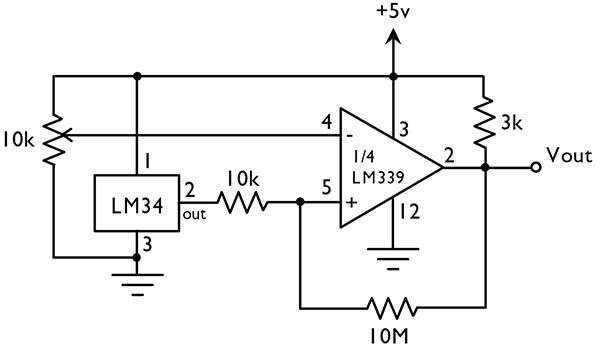
FIGURE 3. Temperature switch circuit.
Once power is supplied to the circuit, you can read what the voltage is at the output (pin 2) on the LM34. You can use a voltmeter to do this. Place the positive probe from the voltmeter to pin 2 of the LM34 and place the negative probe to ground. This will give you an output voltage that corresponds to room temperature, providing a good reference point to figure what the voltage will be for a given temperature. On the LM34, each degree change in temperature will change the output voltage by 10 mV. Use this relationship to figure the reference voltage you need, based on the reference temperature you want.
Now you can adjust the potentiometer so that the reference voltage on pin 4 of the LM339 equals the reference voltage you want (which corresponds to a specific temperature). If you need better accuracy in adjusting the voltage, you can use a potentiometer with a higher value. You can stop adjusting the reference voltage once you read the level you want. If the reference voltage is not going to change, you can replace the potentiometer with suitable fixed resistors.
An Example
Here's an example of how to accomplish this. Let’s say you want to know when it reaches 100° outside. The first thing is to read the output of the LM34 at room temperature. Let’s say that your voltmeter reads 2.34 volts when the temperature is 72°. Now, figure the difference between the two temperatures, which is 28°. Multiply this number by 0.01 (10 mV change for each degree of change) and you get 0.28. Then, add this number to 2.34 and you get 2.62. This is what your reference voltage must be set to. Adjust the potentiometer until the output reads 2.62 volts and then stop. Your temperature switch is ready to go.
Trying It Out
Once the temperature switch is calibrated for a specific temperature, you can test the switch by heating the LM34 with a hair dryer. You can hook up an LED on the output (Vout). Once the temperature reaches the specified point, your LED should go on and stay on until the temperature drops again.
Just like the flashing LEDs, this circuit is easy to build without a microcontroller. You can use it as-is or modify it to suit any purpose you may have. You can also learn a great deal about how comparators work. At the very least, it will spur other ideas on how you can make comparators work for you.
Easy as Pie
These two circuit examples can be used as stand-alone circuits or they may be used in conjunction with others. They can completely replace the use of a microcontroller, or at least take a significant load off of your microcontroller-based project. The examples shown here are only a small sample of what's available for the electronic hobbyist; they are just a couple of ideas and certainly there are many others.
My advice to anyone getting started in microcontrollers and electronics is to get a breadboard, some basic electronic parts (get a grab bag or two), and start experimenting.
To start, keep reading Nuts & Volts and grab a book or two on the basics of electronics. Some of the best I've found for beginners are the Forrest Mims books. Mine is old and beat up, but it’s never very far from me when I experiment. Just like I said at the beginning of this article — microcontrollers are great! Try not to use them as a crutch and, instead, use some of those conventional electronics that have been around for years.
Happy project building! NV
About the Author
Ever since I was about 10 years old, I have been interested in electronics. I went to school to become an electronics engineer, but decided to keep my electronics interest as a hobby instead, so I went into computer programming. Currently, I am a web developer and I love what I do. My favorite electronic device is the microcontroller because it involves my two loves (electronics and programming).