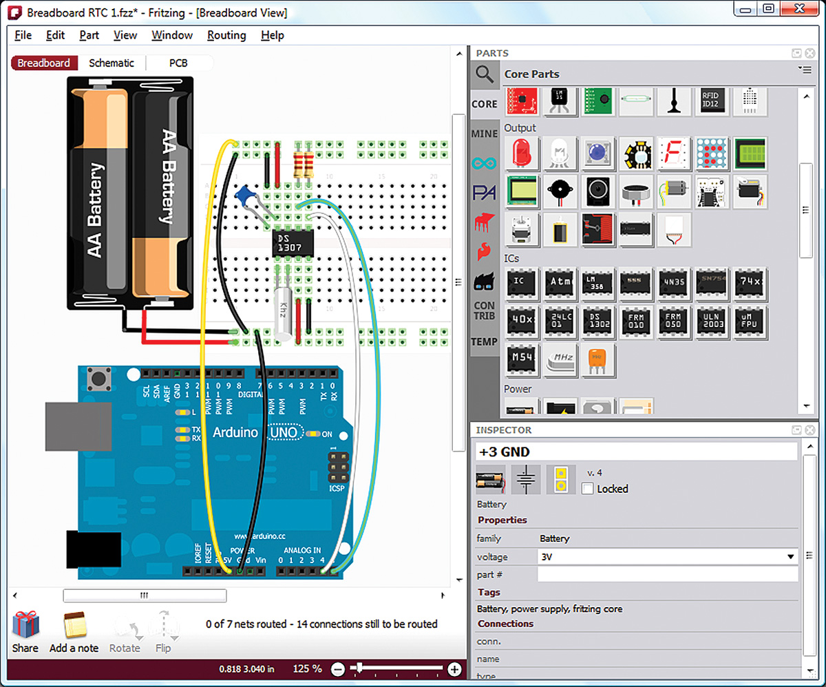
FIGURE 1. Fritzing’s real time clock on a breadboard.
In our previous installment, we continued learning about Fritzing — a novice-friendly electronics hardware design package — useful for things like designing shields for an Arduino. We got better acquainted with Fritzing features and learned how to create some parts. So now, let's go deeper into making parts with Fritzing.
LET'S CREATE A NEW PIEZO SPEAKER PART
A piezo speaker is a useful part since it allows us to have audio feedback using only a single Arduino pin. We will create a part for a piezo speaker described in the datasheet found at www.tdk.co.jp/tefe02/ef532_ps.pdf. You can get this part from Mouser by searching for PS1420P02CT.
We don't really need the datasheet for the electrical characteristics since the Mouser page tells us it is a 5V device and we will be running it with 5V pulses. We do need the dimensions of the part for drawing it, though. We find the shape and dimension illustration in Figure 2.

FIGURE 2. Piezo shape and dimension.
This also includes the paper tape for the devices that come on reels for automatic insertion during manufacture, but we only need the dimensions for a single device.
Figure 3 shows a photo of the devices on the tape; this will help to make our part look more like the original. We see that it is 14 mm in diameter, and the legs are 5 mm apart and 18 mm long.
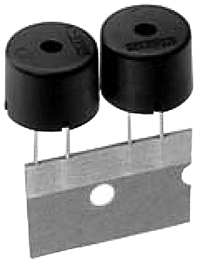
FIGURE 3. The piezos.
Since they have such relatively long legs, we could either plug them directly into a breadboard or we could bend the legs parallel with the bottom and then extend 11 mm over the edge (14 diameter/2 give the radius of 7 which we subtract from the leg length of 18, giving 11 mm).
We can then bend the legs down as shown in Figure 4, thus allowing the piezo to be used on a breadboard without covering holes unnecessarily (as shown in Figure 5).
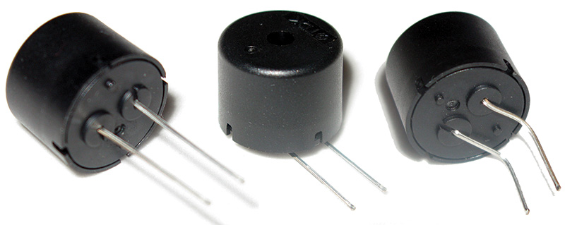
FIGURE 4. Piezos with legs bent.
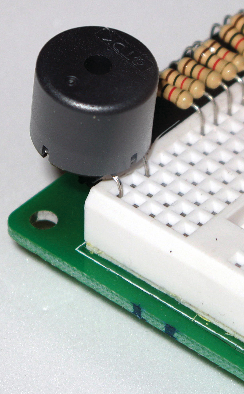
FIGURE 5. Piezo on a breadboard.
Since we will be bending these legs like this, let’s draw the part as showing the legs coming out the side so that it will appear in Fritzing the same as on the real breadboard.
Last time, I discussed why I chose Inkscape to produce the .svg (scaled vector format) for use with Fritzing. The main reason is that it’s free, and as these kinds of programs go, it is not too hard to use. However, I also mentioned that I keep Google open and have to search on almost every command I use. We won’t discuss how to use Inkscape here but I may provide a few hints for things that help with Fritzing.
The first thing you’ll want to do is open the View menu and select Grid. You’ll see a grid appear. Next, open the File\Document Properties window and under the Page tab, change the Default units from px to mm and the Custom Size units from px to mm. Under the Grids tab, change Grid units from px to mm. Now, you’ll be able to draw a circle for the piezo using mm — the dimension we know — and not px (which we’d have to guess at).
To draw that circle, click on the Create Circles, Eclipses, and Arcs icon in the tool bar on the left edge of Inkscape. Draw a circle and click the black color bar on the bottom of Inkscape to generate your base drawing. Next, click the Arrow icon at the top of the left tool bar and you’ll see on the upper toolbar that you have some dimensions to mess with. Click the lock icon to Lock the X and Y dimensions, then enter 14.
Now, you have a 14 mm black circle. If you refer to the photo, you’ll note that the top view of our piezo element has a hole in it and that hole looks a lot blacker than the surrounding area. Okay, so let’s change our base circle to dark gray, then use the same method we used before to create a black circle in the middle.
Use the Fill and Stroke window to set the color of the bounding circle to a lighter gray than the base circle. Use the X and Y boxes to get it centered, and then use the Arrow to draw a box around them.
Next, click the Object menu and Group so that now these two circles travel as a unit. You should have something that looks like Figure 6.
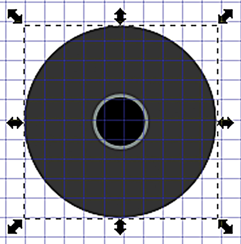
FIGURE 6. Drawing circles.
Next, we want to add the legs that stick out to the side and are bent down. Of course, we’ll only see the top view but these are the legs that we’ll add the connection point in Fritzing to.
Go back to the Document Properties and set the Grid units to ‘in’ and the Spacing X and Y both to 0.1, so we can set the legs to 0.1” centers to match a breadboard. Also, let’s start this up a little with a couple of ‘reflections.’
We use the Draw Freehand Lines tool to draw two lines as shown in Figure 7. (Set the color to white and the rounded ends in the Fill and Stroke window.) Finally — and this is very important — before saving the .svg file, you must make sure you do two things to be compatible with Fritzing. First, in the Documents Properties window under the Page tab under Custom Size, click to “Resize page to drawing or selection;” then, under the File menu use Save As and save the file as a plain svg file. Do not save it as an Inkscape svg file! The final drawing is shown in Figure 7.
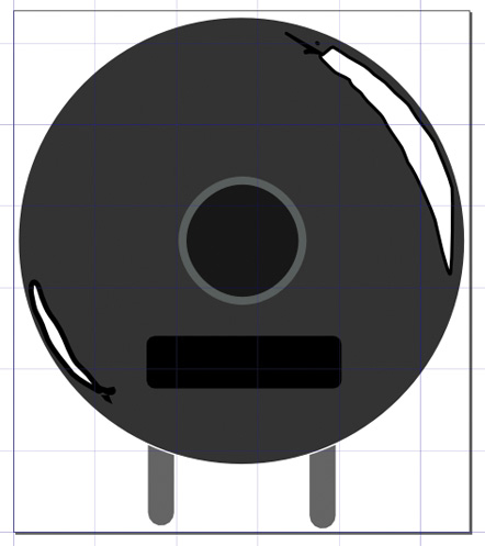
FIGURE 7. Piezo SVG drawing.
USING THE FRITZING PARTS EDITOR
The Fritzing Parts Editor is not quite ready for prime time as of this writing. For simple parts, it’s great, but I had fits trying to do some more complex parts. The guys at Fritzing are actually completely open about this as you can see in Figure 8; you get warned when you open the Parts Editor.
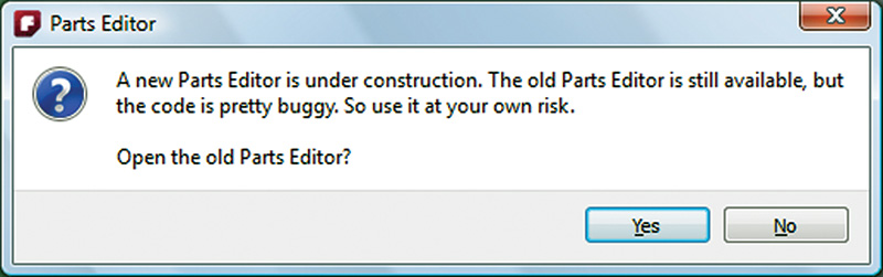
FIGURE 8. Parts Editor under construction.
They (well, Jonathan Cohen) were very helpful and Jonathan is frank that if you want to do anything beyond simple, you’ll probably need to learn how to edit the Fritzing XML files. This is something we do not want to do. Since this part is very simple with only two pins, we can do it without much worry.
Open the Fritzing Parts Editor shown in Figure 9.
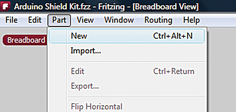
FIGURE 9. Designing a new part.
The editor shown in Figure 10 is used to create a part with four images required for it.
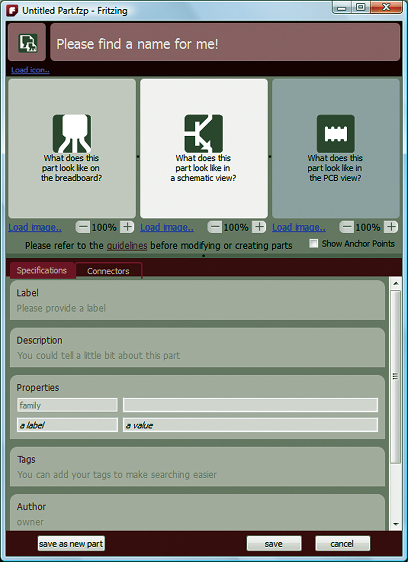
FIGURE 10. Fritzing’s Parts Editor.
These are: the icon, which is a small version of the part that shows in the Parts window; the breadboard image that will show on the breadboard; the schematic symbol that will appear in the schematic drawing; and the PCB symbol that will appear in the PCB drawing. We will use our piezo svg drawing for both the icon and the breadboard part, and we will reuse symbols from the Fritzing directory for the schematic and the PCB symbols.
First, let’s name our part Piezo Buzzer to differentiate it from the existing Fritzing core part ‘Piezo Speaker.’ At the top of the Editor, click on ‘Please find a name for me’ shown in Figure 11, then fill in the name and click Accept. The results are shown in Figure 12.
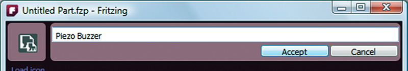
FIGURE 11. Enter a name.
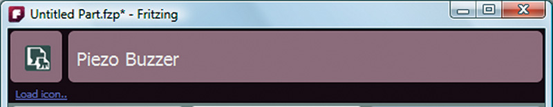
FIGURE 12. Name accepted.
Next, click on the ‘Load icon’ link at the top, and browse to find the piezo.svg file. Click on that, and you’ll now see your piezo image as shown in Figure 13.
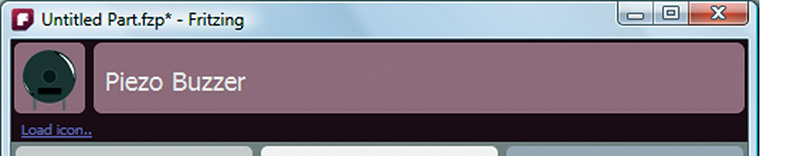
FIGURE 13. Icon loaded.
Next, click on the ‘Load image’ link and browse to the same image; select it and you’ll see what’s shown in Figure 14.
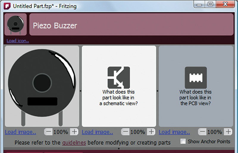
FIGURE 14. Breadboard image loaded.
This shows something neat about vector graphics like our .svg file. It is scalable, so the image can be shown smaller or larger, and in the breadboard image window. In a moment, we’ll see how easy it is to enlarge the image that will help us attach the pin connections. This feature is very helpful as we create the documentation for our projects. We can easily generate a 72 dpi (dot per inch) image for showing in a web browser, or we can generate a 300 dpi (or larger) image when we want to print it to paper.
Now, we want to get the schematic and PCB images. Go to your Fritzing directory and open the parts\svg\core\schematic directory and find loudspeaker.svg. Now, click the Load image link under the schematic window and select that file as shown in Figure 15.
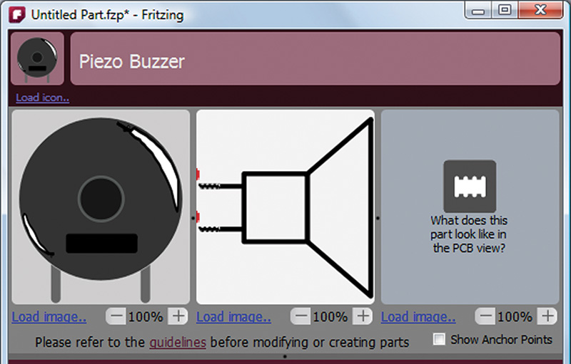
FIGURE 15. Schematic image loaded.
For the PCB image, we need to remember that the pins are 5 mm apart and there are 2.54 mm in 0.1 inches, so we want two holes that are 0.2 inches apart. It just happens that under the PCB directory, we have Buzzer-v15_pcb.svg, so let’s select that and see if it is the right size.
Well darn. It is too big and the holes are too far apart. Good thing we can save some trouble by opening it in Inkscape and adjusting things to fit our needs. We can then save it as Piezo_PCB.svg and import that into the Parts Editor as shown in Figure 16.

FIGURE 16. PCB image loaded.
Fill Out the Part Information
You don’t have to fill out all the information in the Specifications tab. I set the label to Piezo_buzzer; the description to ‘Piezo buzzer PS1420P02CT;’ and the author to me.
Making the Connections
If you click on the schematic drawing and roll your mouse wheel, you can change the size of the image. As you can see in Figure 17, you’ve got two red Xs.
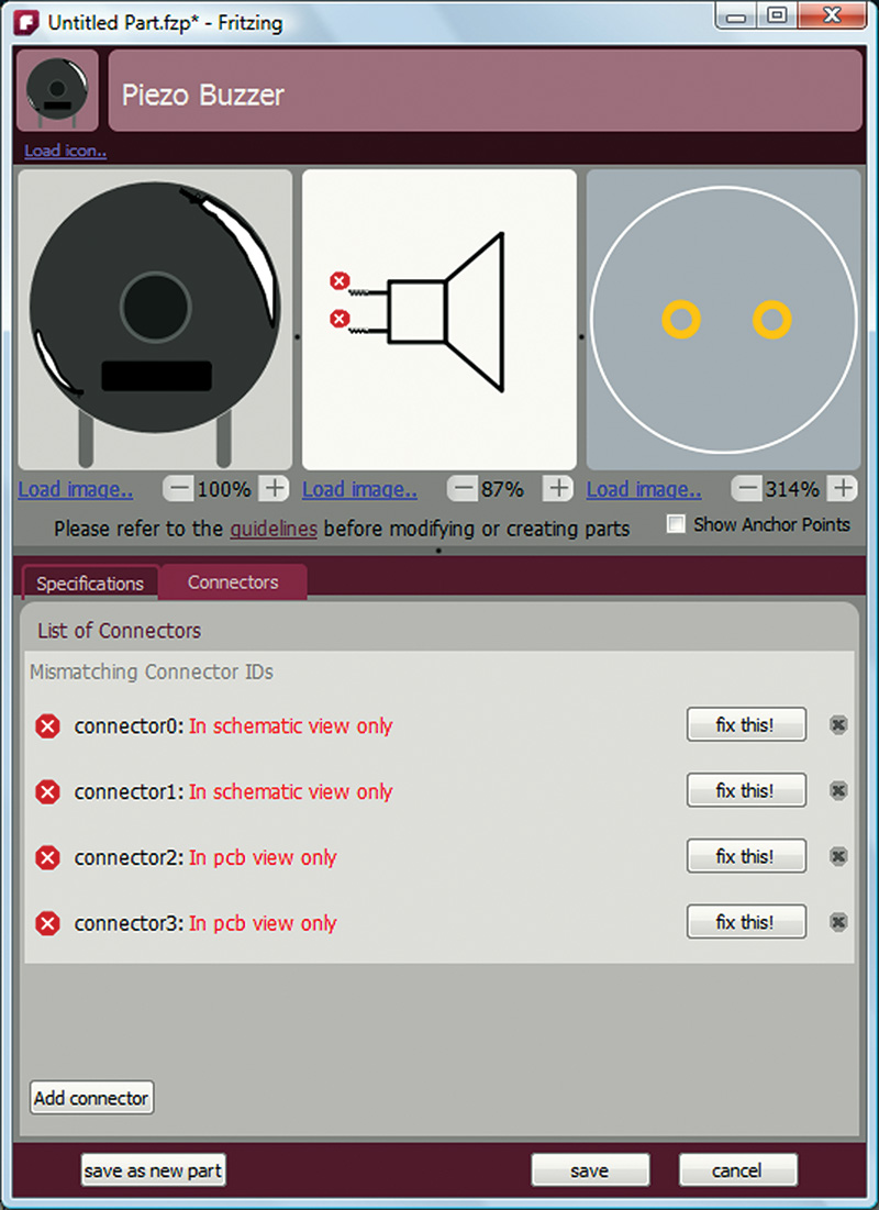
FIGURE 17. Open Connections tab.
This indicates that there are connections in the drawing, but they’re not synched with the rest of the drawings. Click on the Connectors tab and you see four connections listed as mismatched. Just click the x on the far right and get rid of them.
Click the Add Connector button twice to add two connections. Click the gender icon on the left and select the female symbol, then name each pin as shown in Figure 18.
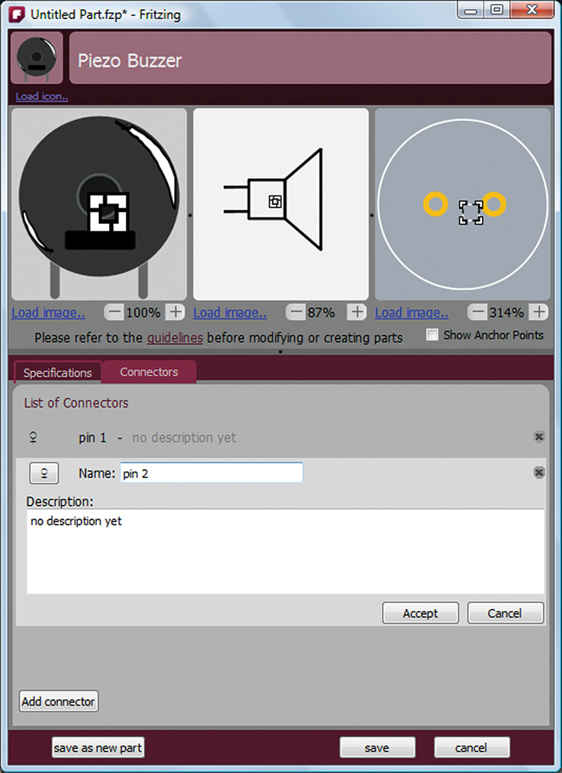
FIGURE 18. Connectors named.
Notice that in each of the images, you see a little white square. This is the connection box and you can select between them by clicking on the list of connectors. It can be very tricky to move these things around and resize them, so you might need to play with this for a while. Select the connector you don’t want to move, and then click on the one you do want to move in the image (yes, weird). Also notice that by holding down the shift, the ctrl, or the alt keys while rolling your mouse wheel makes the image move up and down, left and right, or larger and smaller. Take some time to get these connectors placed properly (as shown in Figure 19) because this is what Fritzing uses to locate wires. If you get them located wacky, your wiring will look wacky.
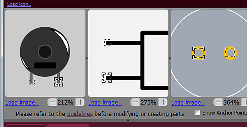
FIGURE 19. Placing the connector.
NOW SAVE IT!
It should appear in the parts bin labeled “MINE” as shown in Figure 20 (minus the other two icons which are a couple of parts I had in my “MINE” bin at the time).
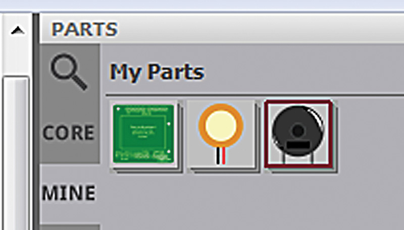
FIGURE 20. “MINE” parts bin.
USING THE RULER
While we were very careful with our measurements when making this part in Inkscape, there are many things that can go wrong. So let’s measure the part in Fritzing and see if it is the size we assume it is. The datasheet said the part was 14 mm in diameter, and we added the connectors with 0.2” separation to match the 0.1” spacing on the breadboard. You can find the ruler in the Core parts bin at the bottom. Drag it out onto the Breadboard work area.
Notice that when we grab the buzzer with our mouse that a box appears around it as shown in Figure 21.
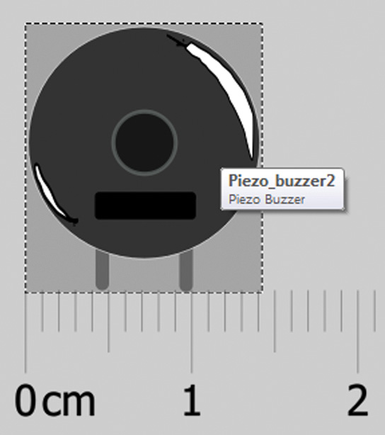
FIGURE 21. Ruler showing our 14 mm buzzer.
This box is the same as the page size in Inkscape and it is the reason that we resized the page to fit the part before saving it. When we move the buzzer to the ruler as shown, it is 14 mm as we expected.
As a final check, we move the buzzer down to the 1/10” rule and see that the connectors are 0.2” apart as we thought (as shown in Figure 22).
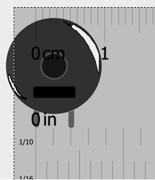
FIGURE 22. Ruler confirming the buzzer connector spacing.
It might seem like a waste of time to re-measure the part after we’ve created it in Inkscape, but early on I made some mistakes and made some parts that didn’t have the dimensions I thought. So, now I double-check.
LET’S USE IT
Let’s add a piezo to our RTC project so we can use this design as an alarm clock. Open the Breadboard RTC Fritzing file we did in our last Workshop. You can use the part you created above, or if you want to save some time you can use the part I created (Piezo_Buzzer.fzpz in the downloads at the end of this article).
In Fritzing, click on the Part menu item and select Import (to import the part). It will appear in the Contributed Parts bin; you can drag it to the PCB and wire it up as shown in Figure 23.
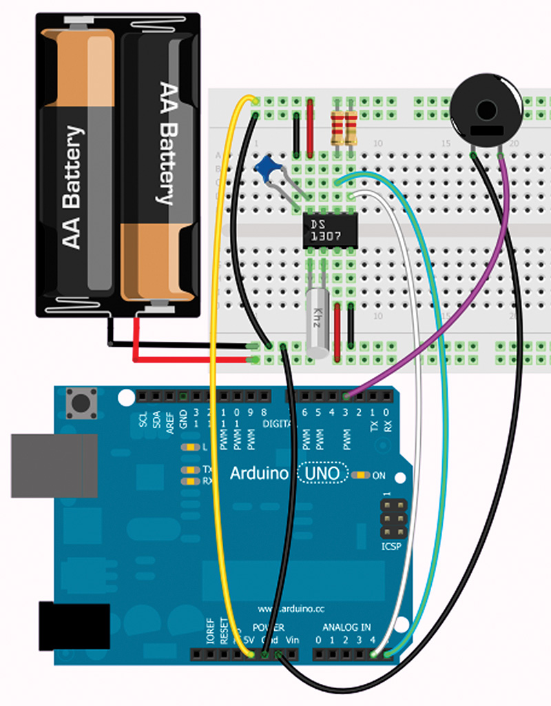
FIGURE 23. Buzzer on an RTC breadboard.
You can then wire the schematic and PCB as shown in Figures 24 and 25.
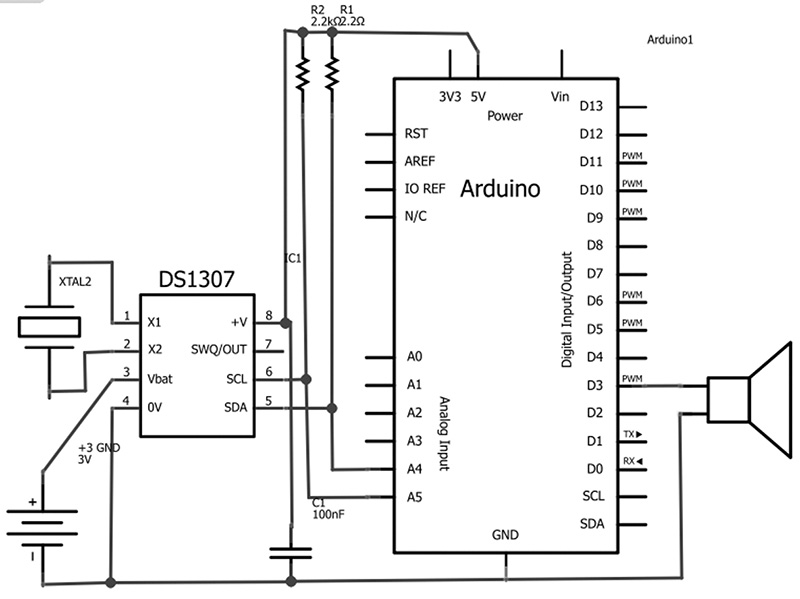
FIGURE 24. Buzzer on the RTC schematic.
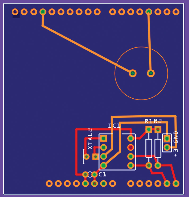
FIGURE 25. Buzzer on an RTC PCB.
We won’t bother to have this board fabricated since it’s a learning exercise.
Sharing Parts
You can share your part by highlighting it, then from the Part menu, click export and save it to a .fzpz file that others can import if they want to use it.
Sharing Projects
After you complete a project, you can share it with the Fritzing community by clicking the ‘Share’ icon at the bottom of the IDE as shown in Figure 26.

FIGURE 26. Sharing projects.
This will take you to the Fritzing website where you can fill out some forms and share your design — a way to give back to the community.
FRITZING EXAMPLE PROJECTS
Like most software tools, one of the best ways to learn to use it is by looking at other people’s example projects. While you can find many on the Internet with a simple search, the Fritzing installation has a bunch of examples included with it that have at least been looked at by someone at Fritzing and judged good enough to include in the distribution.
Open the File menu and then click on the Open Examples item where you will see a list of categories. Click on the Arduino, then expand it as shown in Figure 27; you’ll get to the Arduino Traffic Light example.
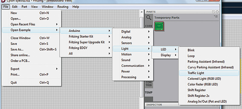
FIGURE 27. Open example for a traffic light.
This will display the traffic light example as shown in Figure 28.
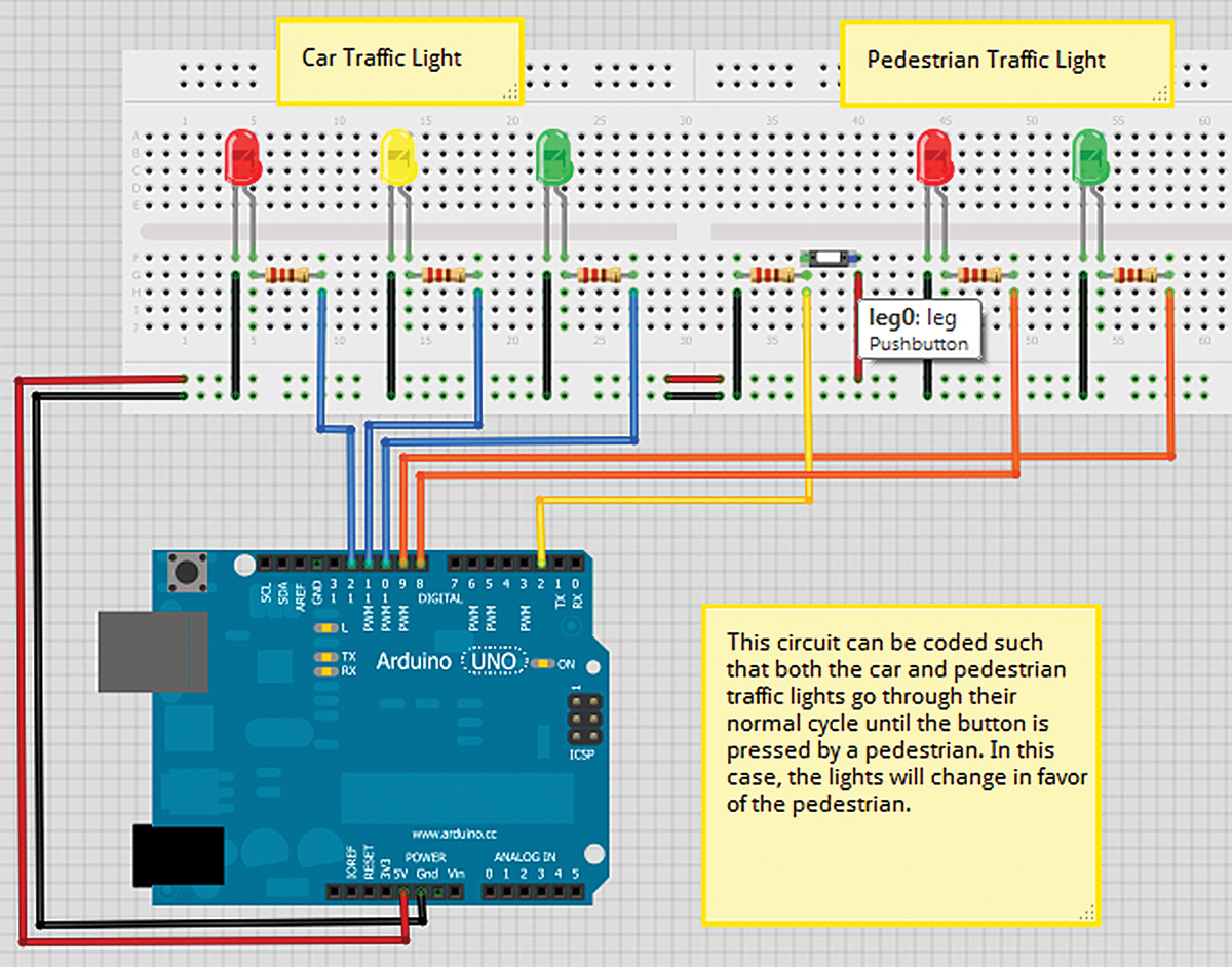
FIGURE 28. Traffic light breadboard example.
You can get the software and additional information from Fritzing at http://fritzing.org/projects/digital-inputoutput-traffic-light as shown in Figure 29.
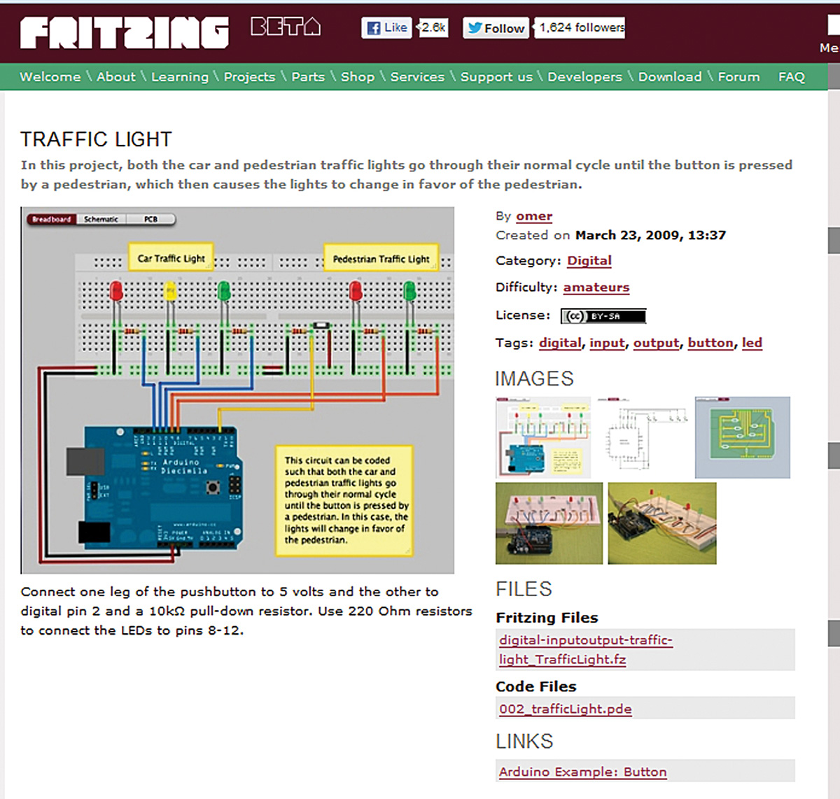
FIGURE 29. Traffic light project on the Fritzing website.
Happy hunting! NV
DONATE TO FRITZING
Another way to give back to the community is to give them some money (Figure 30). Open the Help menu and click on the ‘Donate to Fritzing’ button, then make a donation. Why? Because the only way this great product can get greater is if it gets support from the folks that use it.
I realize nobody has enough money and everybody wants all they can get for free, but I think you should take it as a moral stance that if you are going to use a tool like this, you should throw a few bucks their way to help them out. It is the reason I buy Arduinos.
Of course, nothing forces you to do this, but if you really want to be a member of this growing open source community, you should feel obligated to help out where you can. Sermon over.
Fritzing also has a web shop and sells kits and PCB fabrication services. These are located in Germany and might be more economical for our European friends, but buying stuff from them is also a way to help out.
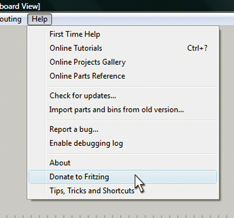
FIGURE 30. Donate to Fritzing.
THE ARDUINO PROTO SHIELD KIT
In our next Workshop, we’ll create the Arduino Proto Shield that uses a mini breadboard to allow quick and easy prototyping. The available kit is shown in Figure A.
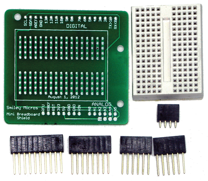
FIGURE A. Proto Shield kit.
You can get a head start on using this board by purchasing it from the Nuts & Volts webstore. Figure B shows a Fritzing illustration of the Proto Shield with an alarm clock prototyped on the breadboard.
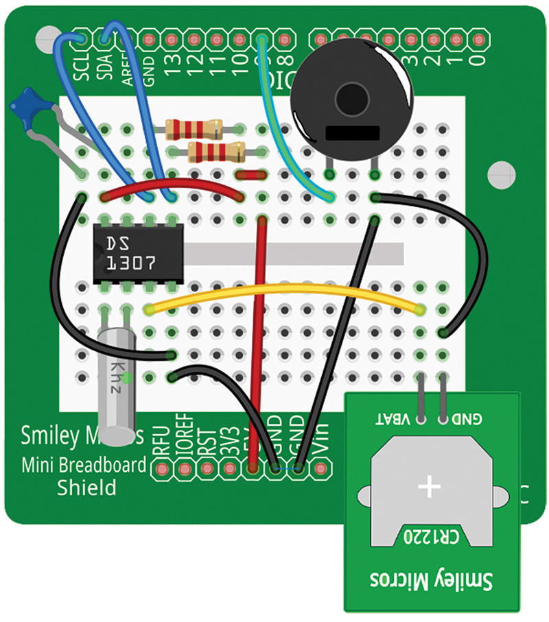
FIGURE B. Fritzing Proto Shield alarm clock.
Downloads
Fritzing file for Piezo Buzzer part from Smiley’s Workshop #52.