Ever want a physical trigger to manipulate keyboard inputs? Then, this is the circuit for you.
A while ago, I was asked by a friend if I could design a simple USB input device to allow substituting keyboard inputs with mechanical micro-switch inputs to operate his TIC-TAC-TOE video game. It was written in BASIC and he didn’t want to re-write any of the program. He also had a wooden box with nine [in a 3x3 matrix] square holes through which a player would throw a beanbag.
As the beanbag went through the opening, a small switch in the bottom of the hole would trigger a contact closure. He then wanted that to somehow trigger the keyboard keys from 0-9, and a foot pedal to send a <backspace> character to reset the game. He had taken an old keyboard and wired into that, but it was clunky, broke easily, and didn't look very nice when he took the game to retirement centers to entertain the people there.
Throw a beanbag through a wooden slot and get a keystroke on a PC. Yes, engineering usually comes in the form of simple problem-solving. So, here goes — let's solve this problem.
Implementation
Now that we know what this project is meant to do, let’s get into the technical aspects of implementation.
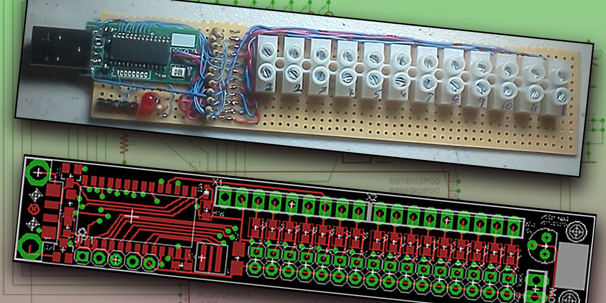
I’ve been designing circuits for a long time now, so I have a sizeable stash of circuit building blocks which get used over and over because they are well known to me and work every time. I’ll be using one of these general-purpose PCBs (printed circuit boards) that’s based on a Microchip PIC18LF2550 that pretty much acts like a small USB thumb drive with several pins of analog or digital I/O. Figure 1 shows my off-the-shelf PCB being used in the original prototype.

FIGURE 1. Original prototype.
Notice the simplicity and flow of this design. Starting on the left, we have our connection to a PC or USB cable, a five-pin programming port, an LED to indicate basic functionality, and a screw terminal array configured to behave as digitally compatible switching inputs via some pull-up resistors. I don’t mean to understate things, yet the circuit design is just that simple. This is certainly a case where the firmware handles the brunt of the task.
All project files are available at the article link, so the schematic diagram presented here is to be used as an outline of behavior. Notice how the schematic generally resembles the image of the original prototype.
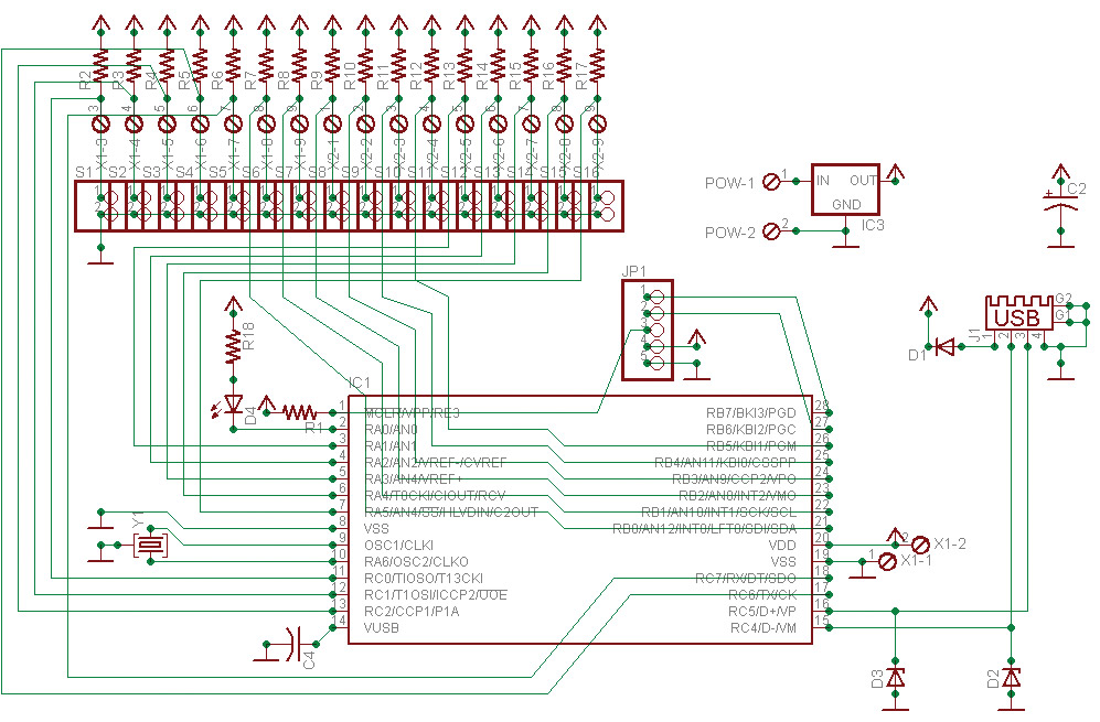
FIGURE 2. Schematic.
There are plenty of standards and opinions regarding circuit design. Keeping things simple and straightforward is usually the best policy to promote understanding and even dreaded troubleshooting. The schematic’s only difference is it has more input switches in the form of pull-up resistor-connected pin headers (top of schematic: S1-S16) and the addition of an optional voltage regulator (IC3).
The switches work as simple closure contacts. For example, R2 (1K ohm to 39K ohms, depending on signal skew and transient rejection desired) is connected serially to the voltage source and to switch S1 (pin header). The other connection is S1 to ground.
When S1 is closed (terminal is shorted to ground), the voltage seen at the junction of R2 and S1 changes from the nominal high voltage (five volts, in this case) to ground (0 Vdc). The PIC will interpret this voltage change as an input logic transition from 1 to 0. Thus, we have a negative logic switch. As long as our firmware knows this, everything will work fine.
Resistor R18 (1K ohms-5K ohms, depending on desired brightness) and diode D4 are the components used to connect an “idiot light” LED to our PIC.
Again, this will be a logic 0 driven output. Other than the output via a USB connection, this will be our only indication of functionality.
The example firmware is written so that the LED will illuminate on device startup initialization and on key presses (switch closures). In my humble opinion, there isn’t much else that would be useful in terms of basic troubleshooting.
The rest of the components are supporting hardware in order to make the PIC happy. Y1 is our ceramic resonator clock source. JP1 is a pin header used for in-circuit programming. Resistor R1 (33K ohms-39K ohms) is the MCLR (programming voltage) pull-up resistor. C2 is a decoupling capacitor with a value of 1 µF to 5 µF. C4 is a ceramic capacitor used by the PIC18LF2550’s internal regulator. There's a range of values that C4 can have, but I’ve found 0.47 µF works the best in most situations.
D3 and D4 are 3.9 Vdc zener diodes used as transient and over-voltage protection for the USB data lines. There are many ways to perform this task. I had a bunch of zener diodes, so I used them. D1 is a 1N4148 type used to isolate the PCB voltage from the USB attached to the PC. If we are using the power from the USB connection, leave D1 connected as shown.
If, for some reason, you choose to use a separate power supply in addition to the PC, remove D1 from the circuit. This will disconnect the PC power from the circuit and allow our own board voltage sources of IC3 or (directly) X1 to power our device. The design used here has the USB as the power source, so as not to damage the PCB or any attached USB host when using optional power connections.
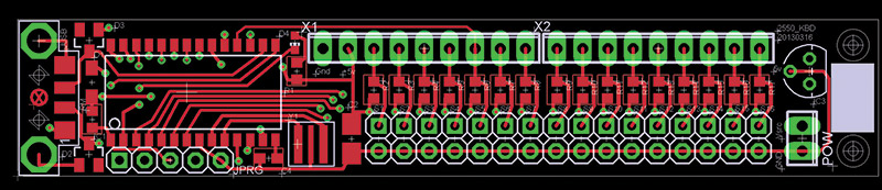
FIGURE 3. PCB layout.
Figure 3 shows our EAGLE produced PCB layout. Notice there's a row of pin headers on the top and a double row on the bottom. The top row is connected only to the junction of the switch pull-up resistor and the switch. These are used in the case where your switches use a shared ground. The bottom double row is used for two wire connected momentary switches as shown in Figure 4. Additional power options are on the right of the PCB.
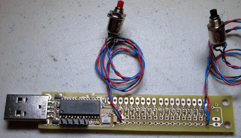
FIGURE 4. The final tested unit.
Firmware
The final piece of the puzzle is that the PIC/PCB needs to act like a HID keyboard device. Luckily, we don’t have to start from scratch because my PIC compiler of choice — CCS’ PIC-C — has been good enough to provide some example USB HID files that we can quickly modify in order to get our device up and running. These files begin with “usb_kbmouseXXX.c” and are within the PCW USB directory of the compiler.
If you do not have this compiler, no big deal. The concept is always the same: Tell the attached PC what kind of HID device we are via the device descriptor, and send messages to (in other cases, receive from) the PC that are accepted as HID type messages. Beyond that, we probably want to tell our PIC what messages (key/scan codes) to send, depending on which key closures are shorted to ground. The provided firmware sends these key/scan codes: 0-9, a-d, <return>, and <backspace>.
Figure 5 is a screenshot of the main function of our PIC18LF2550’s firmware code. We’ll go over the main function first and its generalities, followed by a couple of smaller sections of code that aid in understanding what is actually happening.
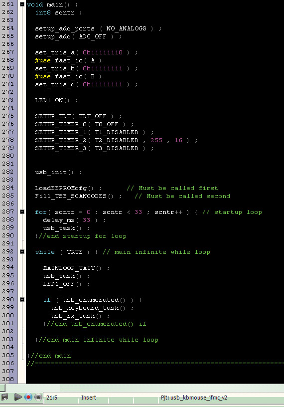
FIGURE 5. Main function of the firmware.
Lines 264-282 get the PIC up and running with configuration and initialization code related to setting port pins as inputs or outputs, registers, and setting up the USB device descriptor.
Line 284 calls our function LoadEEPROMcfg(). This function stores our scan codes into the PIC’s EEPROM area. There's no need to do this. We could have just as easily hard-coded the scan codes, but this would require a complete re-compile of the source code every time we wanted to make a change.
Storing these values in EEPROM allows us to use an EEPROM editor to set the appropriate memory locations with the scan codes that we want reported on a key hit. It simply makes life a little easier in the cases where we either don’t have the correct compiler or like our ROM code just fine.
Line 284 calls our function Fill_USB_SCANCODES(). This function validates our scan code values just to make sure that the data isn’t corrupted or that our values are not out of reasonable range. Knowing my customer, I wanted to make sure that if he accidentally changed the EEPROM stored scan codes to something that was ‘useless’ for his needs, that the firmware could catch it and adjust as needed.
Lines 287-290 are just a short delay that lets our indicator LED stay on for a bit so we can see it. The loop also calls the internal USB service routine periodically so that we don’t miss any of the USB communication events.
Lines 292-303 are the main loop infinite service routine. It is, again, pretty straightforward. We do some housekeeping to keep the USB connection alive, and if we are connected and enumerated on the USB chain, we look for our key hits and send the scan codes as required. Clean and simple.
Now, let’s look at the function usb_keyboard_task() in a bit closer detail. After all, it does all of our task-specific work. Figure 6 is a screenshot of the function that handles the bulk of this work.
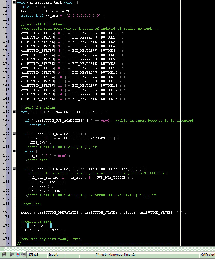
FIGURE 6. The firmware function that processes keyboard hits.
The basic flow is: a) Lines 129-144 scan our key contact inputs for what we define as hits, in this case, a logic 0; b) Lines 147-168 build and send the HID formatted message and turn on the LED for each of our pressed keys; c) Line 170 saves some state information that helps us ignore key presses; and d) Lines 173-174 add in a little bit of delay so that our keys don’t send information too quickly.
There's nothing fancy in any of this, and I’m sure there are many better and different ways to accomplish the same thing. There are only two specific things worth commenting on. The first is that the HID message packet used in this instance is eight bytes long and the key code is placed into the fourth byte (tx_msg[3]). If you look at the function header comment, the detail of the data packet is described. Again, I didn’t do anything fancy here, although we could have been more efficient.
The second is Line 160 shows an if statement that compares the previous key hit to the present key hit. If it's a repeat, we ignore the key until it's released. This instance of how the device is used shows this to be a good feature to have. The de-bounce delay at Line 174 helps to mitigate any transient-caused switching.
Troubleshooting
Troubleshooting this design is pretty straightforward. As with all troubleshooting, we will start with the most likely culprits first:
1) Make sure the device is alive. The firmware is designed so that when the device first powers up our LED will illuminate. As soon as the main loop starts running, that LED will extinguish. Not a fancy check, but it tells us a great deal. It tells us that we have processed all of our initialization code and that the main loop has started. Further, we know that if we get a key hit, the LED will also illuminate and extinguish after our key de-bounce time has expired. So, if our LED doesn’t illuminate on power-up, we either don’t have power or the power is not within the PIC’s range of tolerance. If the LED doesn’t illuminate when a key is pressed (key contact shorted), then we need to check the key connections for opens or shorts, i.e., use a multimeter to check voltages and resistances. There's a possibility that the LED may blink when no keys are pressed. This can occur for two basic reasons: a) The power supply to our device is intermittent. This will cause the PIC to reset and thus re-process our initialization section of code; and b) There could be an intermittent switch closure causing unwanted key presses.
2) Make sure the PC recognizes our device. In most cases (99%+), computers should install the appropriate drivers automatically. Some older PCs (Windows XP SP2 and prior, for example) may not have the correct drivers present. They can be found on the Internet if this occurs.
After the driver installs, open Notepad, simple text, or some other word processing tool. Click some keys (close the key contacts) and you should see the defined scan code key values show up on the screen. If you use the defaults, they will be 0-9, a-d, <return>, and <backspace>. If this doesn’t happen, check your device manager area for the USB connected devices, and make sure the device shows up in the list and has a driver installed. If it doesn’t, you might need to search the Internet for drivers or check the electrical connection to the USB port/device.
For Windows, there's a simple test application called usbview.exe that will neatly show all connected USB devices. There are other tools, but this one usually works fine for Windows. Beyond making sure the drivers install appropriately, I cannot give more detail relative to fixing PC problems without doing a case by case review.
Conclusion
To sum it all up, my friend’s video game operates without problems and the project has successfully fulfilled its designed purpose. As a final note, it should be mentioned that this project is exceptionally ideal for any text input program on the computer and also for inputs to satisfy special programs associated with racing event monitoring, weather status, heat/cold or light/dark monitoring, liquid or chemical, or for any other desired input where outside world entry would be the medium.
There are plenty of modifications that can be made to this basic design. Noise and transient voltage suppression of the input switches could be added, should you choose to use the design in a noisy environment such as in an automobile or in an industrial control environment. You could even modify the inputs to be Hall sensor or photoelectric isolated switches.
The firmware could be modified to send words, sentences, or timed outputs based on hold duration, switch closure combinations, and so forth. As long as your changes are within what the PIC documentation states is allowable and you don’t violate the USB electrical or communication standards, the possibilities are up to you. NV
Parts List
| ITEM |
DESCRIPTION |
MFG PART# |
SOURCE / NOTES |
| C2 |
CAP/TANT 4.7 µF 16V 20% 1206 |
F931C475MAA |
Nichicon |
| C4 |
CAP/CER 0.47 µF 10V 20% 0603 |
C1608X5R1A474M |
TDK Corporation |
| D1 |
DIODE SWITCHING 75V SOD323 |
1N4448WS-7-F |
Diodes, Inc. |
| D2-3 |
DIODE ZENER 3.9V SOT23-3 |
BZX84C3V9-7-F |
Diodes, Inc. |
| D4 |
LED CHIPLED 633NM RED 0603 |
LS Q976-NR-1 |
OSRAM Opto Semiconductors Inc / Not required for operation |
| IC1 |
IC MCU 8-BIT 32 KB FLASH 28SOIC |
PIC18F2550-I/SO |
Microchip Technology |
| IC3 |
REG LDO 5V 0.1A TO92-3 |
L78L05ACZ |
ST Microelectronics / Not required for operation |
| JUSB |
CONN USB A SMD |
1001-011-01101 |
CNC Tech |
| JPRG |
CONN HEADER .100 5-POS |
PEC05SAAN |
Sullins Connector Solutions / Programming Header / Not required for operation |
| POW |
9V BATTERY CONNECTOR |
84-4 |
Keystone Electronics / Not required for operation |
| R1-17 |
RES 39.0K OHM 1/10W 1% 0603 |
RC0603FR-0739KL |
Yageo / Valid range from 1K ohm to 100K ohm |
| R18 |
RES 3.30K OHM 1/10W 1% 0603 |
RC0603FR-073K3L |
Yageo / Valid range from 100 ohm to 5K ohm / Not required for operation |
| S1-16 |
MOMENTARY SWITCH SPST-NO |
GPB024A05BB |
CW Industries / Not required for operation Only two provided in kits |
| Y1 |
20 MHz CERAMIC RESONATOR |
PBRC20.00MR50X000 |
AVX Corp |
| Note: |
Generally, most of these part values and manufacturer part numbers can be substituted. This circuit is very forgiving! So, use whatever you have around as long as it's reasonable. |
A kit is available for this project in the Nuts & Volts Junkbox here.
An assembled kit is available for this project in the Nuts & Volts Junkbox here.
Downloads
Gerber Files, Firmware, Schematics, Materials, PDFs.