My family and friends are increasingly getting spread out across the country (or even across the globe), so keeping in touch can be a problem. This is especially true for someone like me who doesn't really like to talk on the phone much. In addition, there are problems with people's hectic lifestyles and conflicting schedules. When you think of your friend or family member, you may be too busy to call them that instant. Or, if you do, they may be too busy to talk. Thus, the spontaneity of the thought usually just fades away.
I was thinking about these issues in relation to my sisters who are located across the US. I wanted some way or thing that would virtually instantaneously let my sisters know I was thinking of them, but be totally non-intrusive. I wanted them to know without having to disrupt what they were doing with a phone call or text message, and vice versa. I also wanted them to be able to let me know they were thinking of me too.
With these thoughts in mind, I designed what I call a Thinking of You or ToY device.
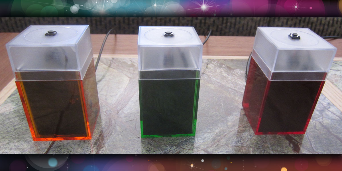
These are small Internet connected devices meant to be used in a home, apartment, work place, or anywhere else with a fixed Internet connection. They should be placed on a desk at the office or in a room at home where they can easily be seen and interacted with. Each ToY device has a single pushbutton switch and an RGB LED for user interaction.
ToY devices were designed to be used in groups. For example, my family’s group is made up of three ToYs: one for myself and one for each of my two sisters. Each ToY device is programmed with Wi-Fi info for each group member and assigned a colorful lighting pattern for the RGB LED that identifies the member within the group.
When these devices are powered up (they are meant to be on all of the time), they connect to the local Wi-Fi network and wait. When someone in the group presses their button (indicating they are thinking of others in the group), his/her pattern is displayed on each device no matter where they are in the world. When other members of the group press their buttons in response, the patterns are appended so all members of the group know who responded. The ToY devices continuously display the concatenated patterns for 30 minutes, then extinguish themselves until someone starts the process again.
The ToY devices are built using an inexpensive module called a NodeMCU Amica that incorporates a ESP8266-12 Wi-Fi module with an embedded application processor. I highly recommend you read my previous article, Meet the ESP8266.
ToYs are really cool, easy to build little devices that I plan on giving my sisters for Christmas. (It’s a good thing they don’t read Nuts & Volts or the cat would now be out of the bag.) Maybe you should consider building these for your family, as well.
As a side note, I have some friends who live across town help me test this concept. I provided them with a ToY device and I had one as well. As we are both early risers, it always made me smile that in the early morning one of us would press the button on our device and the other would reciprocate. Our ToY devices would happily begin pulsating with our assigned patterns, letting each other know we were awake.
The Hardware
The hardware which makes up a ToY device is really quite simple and can be built by anyone with a little soldering experience in an hour or two. The components required for each unit are shown in the Parts List and the schematic is in Figure 1.
| QTY |
DESCRIPTION |
SOURCE |
| 1 |
NodeMCU Amica R2 Module |
Amazon.com |
| 1 |
RGB LED
Common Cathode |
|
| 3 |
1K ohm 1/4 watt Resistor |
|
| 1 |
USB Power Adapter/Charger
1 amp @ 5 VDC minimum |
|
| 1 |
Micro USB Cable — A to Right Angle Micro B |
|
| 1 |
Micro USB Type A Male 5-pin Connector (optional) |
|
| 1 |
PCB Momentary Tactile
Pushbutton Switch |
|
| 1 |
Amac Box Clear #60300
You can also buy two boxes (one colored and one clear) and put the clear top on the colored body. |
containerstore.com |
| |
Frame Matte Material |
Hobby Lobby/Michaels |
| |
Super Glue |
|
| |
Hookup Wire |
|
PARTS LIST.
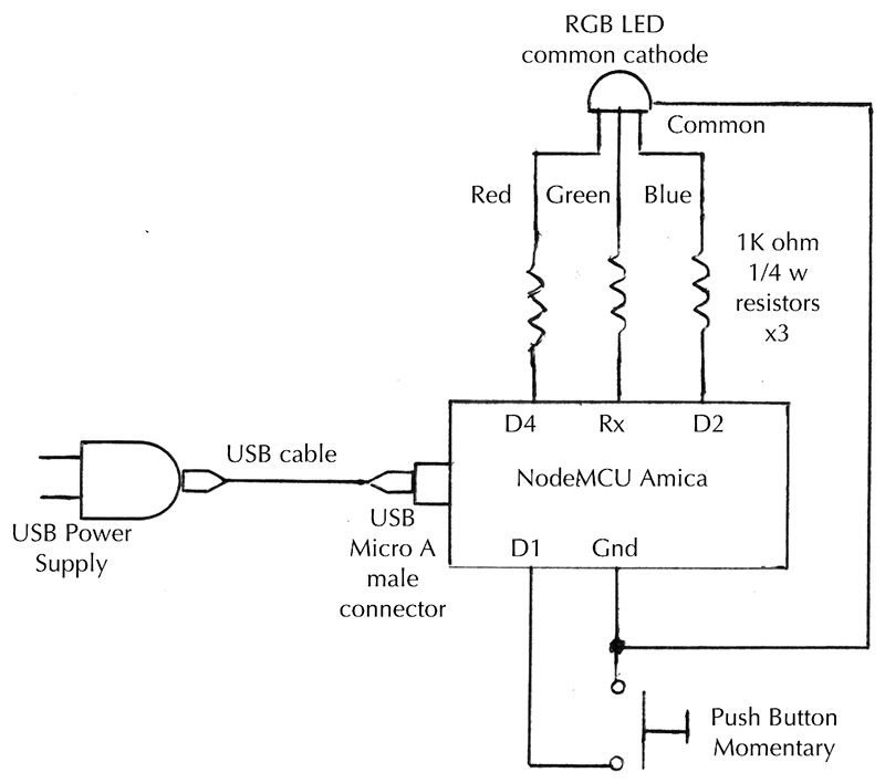
FIGURE 1. Thinking of You device schematic.
The NodeMCU Amica module in Figure 2 is what makes this simple build possible. It consists of an ESP8266-12, along with the support circuitry required to make this module an excellent choice for Internet of Things (IoT) projects and Wi-Fi development.
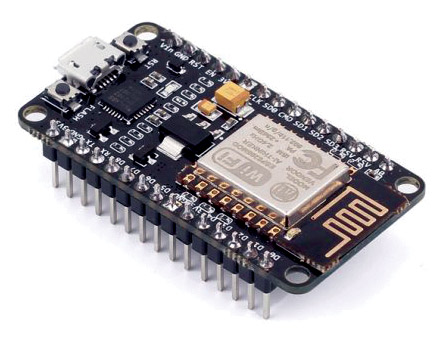
FIGURE 2. The $10 NodeMCU Amica R2 module containing the ESP8266-12.
The ESP8266 is a whole family of Wi-Fi modules which vary in the number of available I/O pins, the amount of onboard memory, the types of interfaces available, and in how the RF antenna is attached/implemented. The ESP8266 module on the NodeMCU Amica has its RF antenna etched directly onto the circuit board. Information on the whole family of ESP8266 devices is available at www.esp8266.com/wiki/doku.php?id=esp8266-module-family.
The following attributes of the ESP8266 family were extracted from its datasheet available at nurdspace.nl/File: ESP8266_ Specifications_English.pdf:
- 802.11 b / g / n
- Wi-Fi Direct (P2P), soft-AP
- Built-in TCP / IP protocol stack
- 802.11b mode + 19.5 dBm output power
- Built-in temperature sensor
- Supports antenna diversity
- Off leakage current is less than 10 µA
- Built-in low power 32-bit CPU which can double as an application processor
- SDIO 2.0, SPI, UART, and ADC
- Standby power consumption of less than 1.0 mW (DTIM3)
In other words, the ESP8266 family of modules features low power consumption, high RF power output, and is capable of supporting all of the current 802.11 standards required for Wi-Fi connectivity. In addition, it supports many industry standard hardware interfaces and can function as the application processor in many designs as it does in this one. The ESP8266 is a 3.3 VDC part.
The NodeMCU module comes from the factory with the LUA programming environment installed. However, since the ToY code was written in the Arduino environment, we will overwrite the factory programming for this application.
The ToY device uses one digital input pin for monitoring the request pushbutton switch and three digital output pins for driving a common cathode RGB LED. Current limiting for the LED is implemented using 1K ohm resistors for each of the three colored LEDs which make up the RGB LED.
To read the switch and drive the RGB LED, we must establish mapping between the general-purpose I/O pins Arduino expects and the physical pins on the NodeMCU module. Figure 3 shows how the NodeMCU pinout helps with this task.
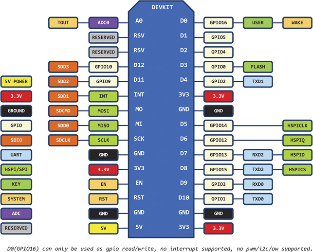
FIGURE 3. NodeMCU Amica module pinout.
The mapping I have chosen for this design is shown in Table 1.
| Function |
Configuration |
NodeMCU Module Pin |
Arduino GPIO |
| Request switch |
Digital input with pull-up |
D1 |
GPIO 5 |
| Red LED drive |
Digital output for PWM |
D4 |
GPIO 2 |
| Green LED drive |
Digital output for PWM |
RX |
GPIO 3 |
| Blue LED drive |
Digital output for PWM |
D2 |
GPIO 4 |
TABLE 1.
The ToY software configures these four I/O lines for the functions shown in the table.
Power for the ToY module is supplied by a USB power supply/charger capable of at least one amp at five volts DC. A weak power supply will cause the hardware to operate erratically (if at all), so make sure the power supply you use is up to the task.
Configuration
ToY devices must be configured before they will function as a group. For each member of the group, the following information is required:
- A name to be associated with the ToY group member. This is only used in debugging messages available through the serial monitor.
- The SSID or name of the Wi-Fi network the device will be associated with.
- The password of the Wi-Fi network the device will be associated with.
- A Teleduino key.
- The selection of an LED lighting pattern for the device.
Each ToY device in a group must have a unique key and LED pattern. Also, each device must exist on a different Wi-Fi network. (With the current software, only one ToY device can exist on a Wi-Fi network.)
ToY devices use the Teleduino service I described in my ESP8266 article to coordinate their activity. Each member of a ToY group must be assigned a Teleduino key (a string of 32 hex characters that uniquely identifies a specific ToY device) which is available for free at www.teleduino.org/tools/request-key. For example, if you have five members in your group, you will need five keys.
After all of the information about the group members is gathered, it must be edited into the devices array within the software (in the ThinkingOfYou.ino file available in the downloads at the end of this article). An example is:
DEVICE devices[] = {
“Sister1”, “S1_SSID”, “S1_PWD”, “S1_KEY”,
redHeartPattern,
“Sister2”, “S2_SSID”, “S2_PWD”, “S2_KEY”,
greenBlueSweepPattern,
“Craig”, “MY_SSID”, “MY_PWD”, “MY_KEY”,
rainbowPattern,
};
There will be one line of data in this array for each group member.
Once the devices array is filled in, the Thinking of You software must be compiled and uploaded into each ToY device. The software installed for each member of a ToY group must be identical.
The Software
Although the ToY hardware is quite simple, the software is anything but. Luckily, you don’t really need to know how the software works in detail to be able to use it. If you are interested in learning how the software works, read on.
The software was developed using the Arduino IDE (Integrated Development Environment). Again, see my previous article for how to set up the Arduino IDE on your computer for targeting ESP8266 type devices. Make sure to select “NodeMCU 1.0 (ESP-12E Module)” as the board type in the Tools menu.
The Thinking of You software is available in the downloads; the file is called Lindley_ThinkingOfYou.zip. To use this software, unzip it and move the ThinkingOfYou directory into your Arduino directory. The Thinking of You software is made up of the files shown in Table 2.
| Filename |
Purpose |
| ThinkingOfYou.ino |
The main program file. This code initializes the ToY device and then runs a rather complex state machine which polls the request switch for activity, queues requests from ToY group members for pattern display, and controls the length of time LED patterns are displayed. |
| LEDControl.ino |
Code for controlling the RGB LED using PWM (Pulse-Width Modulation) and code for color creation and conversion. |
| Patterns.ino |
Defines the colorful lighting patterns that can be associated with a ToY group member. Each pattern is written as a state machine. You could easily add your own patterns once you understand how this software works. |
| TeleduinoClient.h |
The interface specification for the TeleduinoClient class. It defines a class constructor and four public class methods. |
| TeleduinoClient.cpp |
A rather complex state machine that establishes a TCP/IP connection to the Teleduino server and interprets the data it receives back. |
| TeleduinoRequest.ino |
Code for issuing an HTTP GET request to the Teleduino server. |
| Types.h |
Miscellaneous data type definitions. |
TABLE 2.
Once you have the Arduino IDE set up correctly on your computer, have downloaded the code from downloads section, and have edited the devices array with information about your ToY group members, you need to compile the code and upload it to each ToY device in your group. There shouldn’t be any warnings or errors during the compilation and/or upload processes.
When you power-up your ToY device, you should see the RGB LED change color in sequence from green to a whitish blue color and then go off. This sequence indicates your ToY device is working correctly and that it has established a local Wi-Fi connection. If you don’t see this LED color sequence, bring up the Arduino serial monitor and look for error messages which (hopefully) will lead you to the problem and subsequent solution.
Note: There is a small blue LED on the NodeMCU module that indicates the module is powered up. It is normal for this LED to be on all of the time.
How Things Work
When a ToY device powers up, the network name (SSID) and password of each of the group’s members (from the devices array) is passed on to the ESP8266. It, in turn, tries to connect to each sequentially. Once the local W-iFi connection is established, a persistent connection to the Teleduino server is made, and the local ToY device’s key is passed to identify itself. The Teleduino server first verifies the key is valid and then begins a message exchange with the ToY device to verify it is up and running. This exchange — managed by the TeleduinoClient code — repeats approximately every five seconds to verify the ToY device is still alive and well. This process will continue as long as the ToY device is powered up.
An HTTP GET request targeting each group member is sent to the Teleduino server when any one of the ToY group members presses its button. Passed in this request is the index into the devices array of the device making the actual request.
The TeleduinoClient code in each group member will then receive an event from the Teleduino server which indicates which ToY device made the request. A lookup in the devices array then retrieves the function pointer for the LED lighting pattern corresponding to the ToY device that made the request. This pointer is added to the LED pattern display stack. Code running in the background sees that the display stack is no longer empty, and starts the LED lighting pattern on each ToY device.
If and when a group member responds, its display pattern is appended to the display stack and the patterns display sequentially.
A background function monitors how long the patterns have been displayed. After 30 minutes of no switch activity, it clears the display stack and turns off the RGB LED.
Packaging the ToY Device
I wanted the ToY devices to be as small as I could easily make them and as unobtrusive looking as possible. I definitely didn’t want them to look like a bunch of wires and parts kludged together since they will need to be placed in a conspicuous place to be seen and interacted with.
Fortunately, I had just visited a Container Store and remembered these cool little vividly colored plastic boxes I thought would work perfectly. They come in all sizes, but I picked one with dimensions of 1-5/8” x 1-5/8” x 2-7/8” which would easily fit the NodeMCU module with room to spare. I decided to buy two of these boxes for each device: a clear one and a colored one. I would use the top of the clear box and the bottom of the colored box together. This would allow the light from the RGB LED to radiate from the top of the box but would help hide the electronics in the bottom.
With that decided, I used steel wool to frost the clear top to diffuse the LED’s light. I then drilled a hole in the middle of the top for the miniature pushbutton switch. I used a small file to create a square hole for the switch and then used a couple of drops of Super Glue™ to hold the switch in place.
Next, I cut the small connector off the end of a USB cable as I needed to feed the cable through a hole in the bottom portion of the box. I also decided the electronics were still too visible, so I cut four pieces of black frame matting to fit inside the bottom of the box. This not only hides the electronics, but forms a support for mounting the NodeMCU module as well.
Figure 4 shows two units being prepped for assembly.
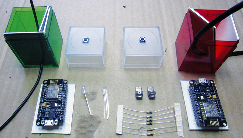
FIGURE 4. Preparation for construction.
Here, you can see the frosted tops with attached switches, the USB cables fed through the sides of the colored boxes, the pieces of frame matting, and how each NodeMCU module was attached to a piece of the matting with drops of Super Glue™ in each corner.
All of the electronic components are soldered directly to the NodeMCU module except for the switch which is wired to the module. (This can be seen in Figure 5.)
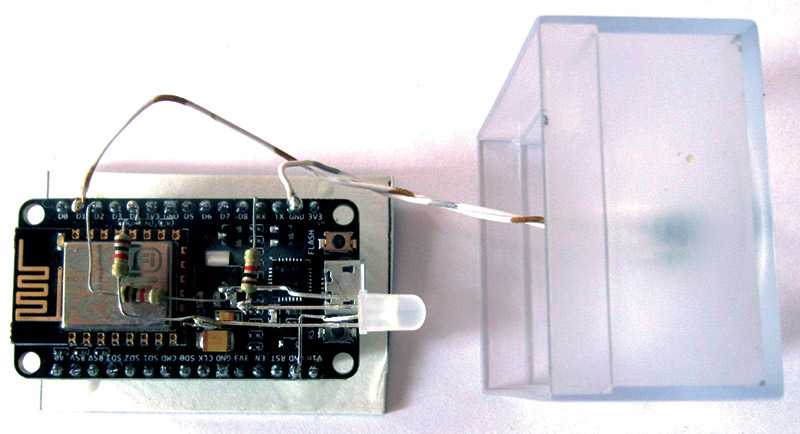
FIGURE 5. Assembly complete. Note: The NodeMCU module is Super Glued to the frame matte material.
I formed the resistor and LED wires to be as short as possible to insure they are mechanically rigid. I also made sure the LED was placed off to the side of the USB connector on the NodeMCU module so my modified USB cable could be easily attached.
As mentioned, I had to cut the end off of the USB cable so that it could pass through a small hole in the side of the plastic box. It would be possible to strip the wires from both ends of the cable and reattach the micro USB connector, but I decided to use a new connector instead. This would allow the cable/connector to have a lower profile so it wouldn’t extend up into the clear plastic box top.
With the cable completed, I attached it to the NodeMCU unit and slid it into the colored box bottom. I then inserted the other three pieces of matting material and held them in place while I put a drop of Super Glue in the corners to hold them together. Placing the clear plastic box top onto the bottom completed the construction.

ToY device is smaller than a coffee cup.
Conclusion
Keeping in touch with family and friends is very important in the hectic world we live in. That, however, is not the only use for a ToY device. It could be used, for example, to alert your friends across town that it is time for beer o’clock, or it could be used to monitor your child(ren)’s continued presence at someone else’s house, or to inform your morning car pool members you are on your way ... the applications are endless.
For me, I think this will make a nice Christmas present. With a touch of a button, we can let loved ones know that we are thinking of them all year long. NV
Resources
Information about Teleduino
www.teleduino.org
Information about programming the ESP8266 in the Arduino environment
github.com/esp8266/Arduino
I would like to thank my friends, Dave and Barbara Resch for helping me test the Thinking of You concept and the actual devices.
Downloads
Lindley_ThinkingOfYou.zip
What’s in the zip?
Source Code