It was a dark and stormy night. Two small children were walking down the dimly lit sidewalk. The full harvest moon was peeking out every now and then through the small breaks in the clouds. A dog was howling on an eerie note. Spooks, goblins, and vampires could be seen on the other side of the street. The children slowly walked up to door with bags in their small hands. As they crept up closer, on the wall there was a strange picture of a skull or was it a lady sitting at her mirror? As they draw nearer, all of a sudden there is a great flash of light and Shazam! A lightning bolt from the picture flashes with a great clap of thunder!Halloween is one of America’s (and my) favorite holidays. It has become progressively more and more popular with parties, and probably is in second for outdoor displays next to Christmas.
This project was designed to be flexible and reusable for other holidays, and the basic unit can be put together for less than $15 plus the board. No surface soldering is required, so this is an easy first time project. Depending on what type of display you use, the price can increase. Plain LEDs are cheap. I used high output white LEDs which sell for $.89 ea. If you want 100 lumens per LED, the price can jump to $8 ea, and you will need to add drivers. For those who want lighting for a stage production, simply can use photo triacs (Sony S211602F) and drive up to 16 amps 220 volts for each bulb.
If you don’t want sound, leave out the sound chip and save money. The board can be triggered using a momentary switch. The one described in this article uses a Parallax Passive Infrared detector (PIR) for detecting the presence of a person. The PIR is also available at RadioShack for $9.99. My project ended up costing about $40. This doesn’t have to be a one-time project. I have put in programming pads, so if you have a PIC 2 programmer you can program the light output for Christmas, Valentine’s Day, birthdays, etc. Changing the DIP switch will allow you to code many different programs. The voice chip can be reprogrammed by the DIP switch giving you many choices of different tunes. If you use the PIR, it can be utilized in a lot of other projects as it is a plug-in module.
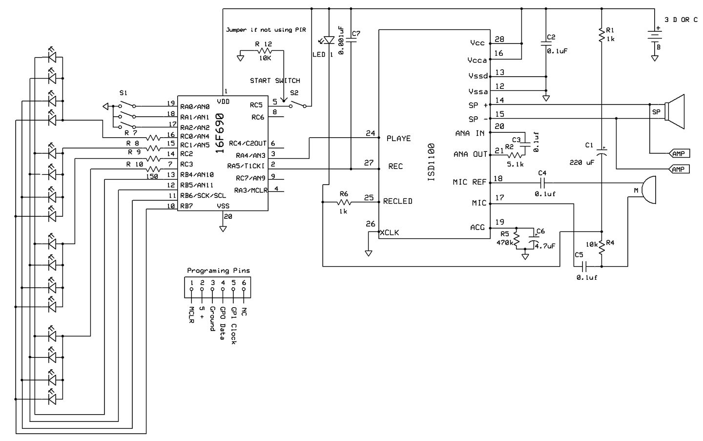
Display Chip
The heart of the board is a Microchip PIC16F690. It also controls the sound module. The board will provide 30 milliamps for each of the 16 LEDs using a multiplexing technique. The eight outputs are divided into two sections of four outputs (42 = 16). The LEDs are set up in four groups of four with their anodes tied together. The first cathode of each group is daisychained together. Same with the second, third, and fourth LED. By applying a positive voltage to group one and grounding LED one, it will light; grounding LED two, it will light; and so on.
The PIC is triggered by shorting the two terminals labeled S2. There is also a jack to plug in the PIR which will detect a person’s presence using infrared sensing. Both S2 and the PIR provide a positive voltage to trigger the PIC. I added a three-position DIP switch so that you can program nine different modes (32 = 9). The switch also controls if the voice chip is being used for recording or playing. If you’re not using the PIR and if S2 is kept shorted (using a shorting bar), the unit can cycle at 30 seconds, one minute, two minute, and four minute cycles, depending on the DIP switch.
Voice Chip
The voice chip is a CMOS device which uses five volts to power it. It has 10 seconds of memory for storing the sounds, a microphone preamplifier, and speaker outputs. I added a 1/8” jack so that you can plug it into a stereo amplifier for big claps of thunder. Instead of using pushbutton switches as shown in the ISD1110P schematic which can be downloaded from the Nuts & Volts website (www.nutsvolts.com) or from Jameco.com. It is driven by the microprocessor so that the timing coincides with the lightning flash.
I got the thunder sound off of the Internet. The “PLAYE” input was used as this allows the PIC to return to its high state and the voice chip will continue to run. The chip is capable of providing 12.2 milliwatts. Once it finishes, it goes to sleep.
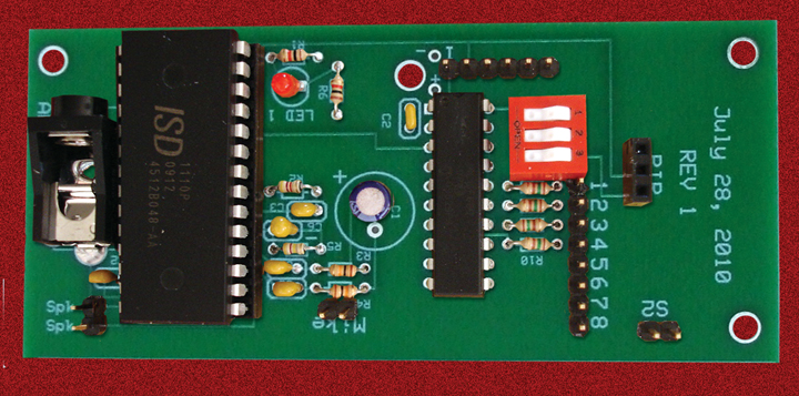
Construction
The board files, along with several other downloads, are available on the Nuts & Volts website (click “Magazine” and then “Downloads” and find “Shazam”). You will need to download the free software from www.expresspcb.com to view the schematic and the PCB (printed circuit board). (However, I think you will find it cheaper to order the boards from the Nuts & Volts store.) Also available is a pre-programmed PIC16F690 if you don’t want to program it yourself.
If you don’t have a PIC 2 programmer and still want to program, put a 20-pin socket in IC1 and solder. Note that the square pin is pin 1 on both ICs. Solder IC2, the resistors, and capacitors into their proper areas. I put an extra pad in for C1 so that you can use either 2.5 mm or 3 mm radial capacitors. Note the “+-” on the 220 µF and 4.7 µF caps. Solder in the three male headers at SPK, the mic, S2, the five male headers in the programming pads, and the three-position female headers in the PIR area. If using a three D, three C, or three AA battery pack, thread the wire through the strain relief hole and solder the red lead to the + and the black to the -. (All chips will run on 4.5 volts.) You can also use a five volt battery eliminator. Do not use four batteries as the PIR will lock up!
If programming with a PIC 2, make sure you place the DIP switches in the open position. The chip can also be programmed by other programmers if it’s removed from the board. The assembly files are also on the N&V website.
 Display
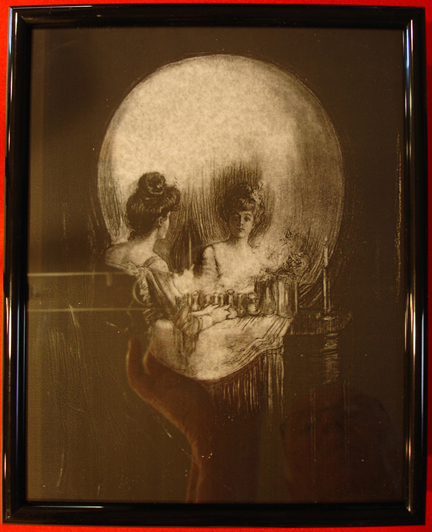
The display I built is rather unique. I made a transparency of the picture drawn by Charles Allan Gilbert called “All is Vanity.” It is a picture of a woman sitting in front of her mirror and vanity. However, when viewed farther back, it becomes a skull. The picture is available on the N&V website if you want to use it.
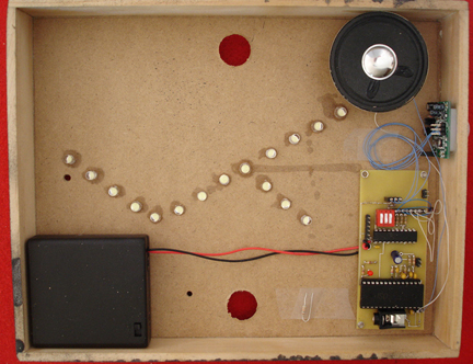
The frame I used was the cheapest 8” x 11” stand-up frame I could find. The back was removed. I tacked the transparency on each corner to the glass using super glue. A sheet of white tissue paper was tacked to the transparency on each corner giving a semi transparent background but still showing off the picture. I took the back and added a 3/8” x 1” pine strip to make it look like a shadow box mount and painted the outside with a flat black paint. The inside was left unpainted. Holes were drilled in a zig-zag pattern with a #60 drill for the LEDs. The Superbrite LEDs were pushed through the back and held with wire wrap. The circuit board was mounted on the inside of the box in the left lower corner using 1/4” standoffs and 6-32 screws. However, I found that the PIR would not detect through either the transparency or the glass. I ended up drilling a 7/8” hole through the bottom of the picture frame and inserted the PIR into this hole from the inside, then tacked it with hot glue. I used a 3-pin male header and plugged it into the PIR female header, then wire-wrapped the PIR using the wire as an extension.
There are mounting holes in the board, and the 1/2“ 6-32 screws will self tap. When the PIC is triggered, a bright flash of lightning comes from the picture. The frame was placed above my stereo speakers and the output from the voice chip was fed into the stereo input. A clap of thunder comes from the stereo speakers and really makes people jump.
If you don’t want to use this particular picture, you can also mount the LEDs on a piece of white (how about a ghost hanging from the ceiling) or black felt (in a dark corner), depending on the effect you want. Zig-zag the LEDs in groups of four. There are a hundred and one possibilities!
Starting from the top of the zig-zag, use a wire-wrapping tool and 30 gauge wire wrap (available from RadioShack). Wrap the anodes of the LEDs in sets of four, e.g., LEDs 1, 2, 3 and 4 to pin one. Then do 5, 6, 7, and 8 to pin 2; 9, 10, 11, and 12 to pin 3; and finally tie 13, 14, 15, and 16 to pin 4.
Daisychain the first LED’s cathode of each set together and wire to pin 5, e.g., LEDs 1, 5, 9,and 13 to pin 5; LEDs 2, 6, 10, and 14 to pin 6; LEDs 3, 7, 11, and 15 to pin 7; and the last LEDs 4, 8, 12, and 16 to pin 7. It is important to keep the sets in order for the flash to appear going downwards (see Figure 7).
PIR
The PIR sensor is a pyroelectric device that detects motion by measuring change in the infrared (heat) levels emitted by surrounding objects. It uses a crystalline material that generates an electric charge when exposed to infrared radiation. If used, it takes about 60 seconds before it functions properly. The jumper should be placed on L. The PIR specifications state the voltage for the chip should be from three to five volts. Although it would fire, it would not activate the PIC using six volts.
Software
I placed the reading for the trigger at the beginning of the program so that you can change the DIP switch any time. After it is triggered, it will read the DIP switches.
Some of you who are new to programming may wonder what the “ANDWF” command does in the “STARTING AREA.” The DIP switches for programming the chip are connected to port A’s RA0, RA1, and RA2. These pins are configured to have pulled-up resistors, so all we have to do is to change the DIP switches from open to closed to configure the pins either high or low. There are other connections to port A besides the DIP switch. To read just the first three pins, you use an AND command. You can AND B’00000111’ (B is for binary) or you could also use a “.7” decimal number. A zero will eliminate any ones. The ones allow either a one or zero to be read. If we just AND port A, it will change its outputs which you don’t want it to do. So, you place port A into a TEMP register and AND the TEMP registers instead.
After “START,” the strobe effect is created by using a series of flags and setting the flags after an LED is turned on. The first time it is turned on, it jumps back to S1. However, once turned on, its flag is set and it will continue on to the next LED. Note that all the flags are cleared at the beginning of the “START” sequence.
Once the strobing is finished, it turns on the voice chip and continues with a series of delays and flashes. The “CALL” feature is a great way of performing the same function over and over. You simply call the procedure you want; at the end of the procedure, you place a return and it will go back to the command after the CALL.”
Running Shazam
Use either a small 16 ohm speaker or (better yet) plug your stereo into the jack. Set all the DIP switches to open. Put in the batteries. Place R12 across the PIR pins 1 and 3; short S2. The LEDs should flash downward and then the voice chip will activate. The LEDs will flash again. If you leave S2 shorted, it will flash every 30 seconds. You can change the DIP switches to increase the time. If you short and release, it will flash each time you short after the sound finishes at the time level the DIP switches have been set to. R12 prevents false triggering when using a switch.
Remove R12 and plug the PIR into the female headers on the Shazam board (if you are using it). When it detects the presence of a person, it will flash and wait for 30 seconds before flashing again. Delays can be set via the DIP switches so it won’t keep flashing.
Recording
Remove the PIR module. Connect a microphone or tie the headers into the earphone outlet of your computer and connect it to the headers titled “MIC.” Put one DIP switch in the closed position and the other two in the open position. When ready, short S2, open S2, and short again to record. The LED will light indicating that the chip is recording. Wait until the lightturns off.
There are many thunder sounds available on the Internet. Just perform a search for “thunder sounds.” Use a 1/8” plug with about 6” of wire-wrap; put the plug into the ear phone jack of your computer and wrap the wire around the “Mic” pins. Push both the play button on your computer and short S2 at the same time to record. The chip will record 10 seconds of sound. If you goof, try again.
Happy Spooking!! NV
Parts list is included in the Shazam download zip below.