FIGURE 1. Google Map of Port Saplaya, Spain.
Attention Readers - SInce Google Code is shutting down, Avrtoolbox has been exported to https://github.com/nutsvolts/avrtoolbox. At this time, not all of the code files mentioned in the Smiley's Workshop series are available there. We are working on the problem and hope to have it resolved very soon.
Recap
Last time, we continued looking at tools to put in our avrtoolbox and added the C Standard Library, paying special attention to the venerable printf() functions. We finished by developing a command-line interpreter tool. Now, we are going to dive into digital I/O (Input/Output). I’ve checked the depth, so you probably won’t hit your head on any rocks.
Ports?
If you ever wondered why a group of pins on a microcontroller might be called a port, you need look no farther than Figure 1 — a Google Map of Port Saplaya, Spain. The sea can be a wild and dangerous place where ships batten down and fight their way through storms until they get to the safety of a port. In a port, the waves are broken and the ship is safely tied to a dock where goods can be moved (ported) to and from warehouses and highways.
A microcontroller port is analogous to a seaport in that the pins of a port buffer the sensitive inner workings of the microcontroller from the chaotic outer world, allowing you to safely move digital data to and from the processor core. In practice, we apply the term port to several different kinds of input and output: We have various serial ports such as the USART or SPI, and we have the topic of this month’s Workshop: digital I/O ports, which are arrays of eight pins considered as a unit.
Why eight pins? This is because the ports are peripherals that are viewed by the AVR processor core as being memory locations, and the AVR addresses memory as locations for eight bits of data. The AVR core knows nothing about the electrical vagaries of the outside world, leaving the conditioning electronics to sort that out. The core just sees a port as a memory location that it can read data from or write data to.
Pins?
The Arduino folks made a radical (okay, that’s my opinion) decision to ignore the port concept and present the novice with pins as individually numbered entities independent of any other pin. That is a great simplification for the novice, and maybe that isn’t even so radical since the AVR does guarantee that you can change and use any pin of a port without affecting any other pin on that port.
So, let’s go with this idea of pins as separate entities and ignore ports for a moment, and present a pin-based Arduino-like elementary digitalio library for our avrtoolbox. This library is written for the ATmega328 (which I tested on an Arduino board) and the AVR Butterfly which uses the ATmega169.
Avrtoolbox Digitalio Library
The avrtoolbox digitalio library — like most of our elementary libraries — looks a lot like something from the Arduino. This is intentional and provides a transition for the novice Arduino user to progress to using the more professional AVR C programming resources: AVRStudio, WinAVR, avrlibc, avr-gcc, etc. Once you decide you are ready to move beyond the Arduino, you have the elementary avrtoolbox libraries and associated source code to let you see how this is done in C (okay, you get to see how I think it ought to be done in C). Don’t get me wrong. I love the Arduino and use it all the time, even in ‘professional’ projects, but it was never intended to be a full-fledged development environment, so I’m trying to provide the tools that will help make the transition easier.
Digitalio Functional Requirements Specification
Digitalio Initialization Function: Allows the user to set a pin as either input or output, with the option of using the output pull-up resistor or not.
Digitalio Input Function: Allows the user to read the digital state of an input pin.
Digitalio Output Function: Allows the user to set the digital state of an output pin.
Digitalio Application Programmer’s Interface
pin_mode() – Digitalio Initialization Function
Description: Sets the specified pin to either input or output.
Syntax: void pin_mode(uint8_t pin, uint8_t mode)
Parameters:
Pin: Pin to set the mode for.
Mode: Either INPUT or OUTPUT.
Returns: Nothing.
Example: pin_mode(9, OUTPUT);
digital_read() – Digitalio Input Function
Description: Reads the state of the indicated input pin.
Syntax: int digital_read(uint8_t pin)
Parameters: Pin: The number of the pin to read.
Returns: HIGH, LOW, or ERROR.
Example:
// wait until the monkey pushes the
// button then give him some candy
while(digital_read(8) == HIGH); // wait forever for the button push
digital_write(9,HIGH); // open the candy door
digital_write() – Digitalio Output Function
Description: Sets the state of the indicated output pin.
Syntax: void digital_write(uint8_t pin, uint8_t value)
Parameters:
Pin: Pin to set either HIGH or LOW.
Value: HIGH or LOW.
Returns: Nothing.
Example:
if(digital_read(8) == LOW) // did somebody trip the
door sensor?
{
digital_write(7) = HIGH; // if so, turn on the lights
}
The Source Code
This code is written for both the Butterfly and the Arduino board using AVRStudio (not the Arduino IDE). If you aren’t already familiar with how to do this, you may want to refer to earlier Workshops to review how to compile and upload the code.
The tester is very simple and merely reads the DIP switch and shows the state on the LEDs. Once you build the hardware for this and get it all working, be sure and save it for later when we will do some more complex things using the same setup.
Using the Digitalio Library With the Butterfly
Since this about input and output, let’s dig out that eight-bit DIP switch and use it to set the states on eight LEDs. In Figure 2, you see the Butterfly pins for ports B and D shown as pin numbers to use with the digitalio library. The test program — as usual — is located in the testers directory at https://github.com/nutsvolts/avrtoolbox. The functions are in the /source/elementary/digitalio directory and the tester is in the /testers directory. Rather than use a precompiled object library in digital_c_tester_butterfly, I include the source for the digitalio library functions since these functions are small.
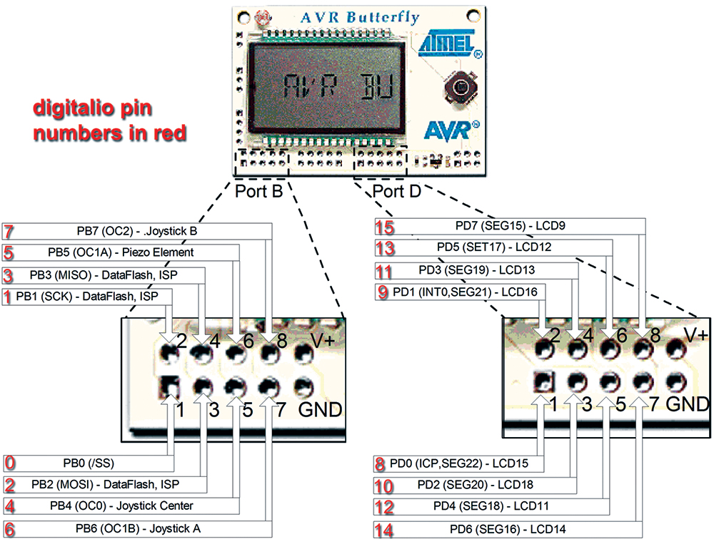
FIGURE 2. Butterfly pin numbers.
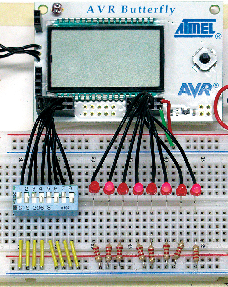
FIGURE 3. Testing digitalio using the Butterfly.

FIGURE 4. Schematic for DIP switch to Butterfly pins 0 through 15.
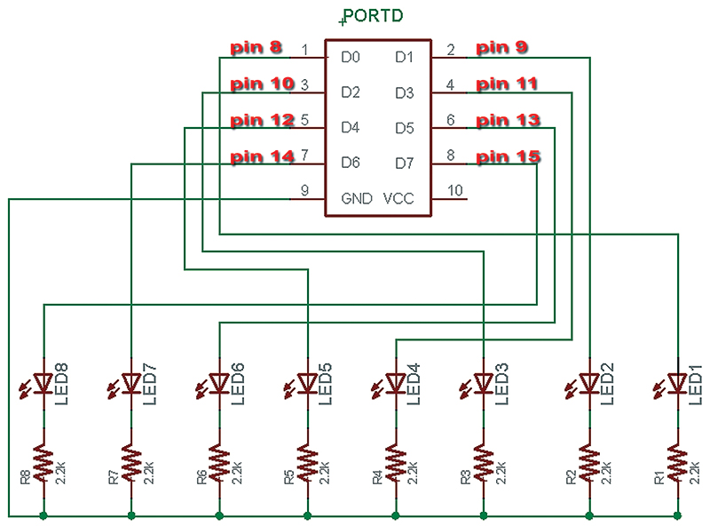
FIGURE 5. Schematic for LEDs to Butterfly pins 8 through 15.
Using the Digitalio Library With the Arduino
Our work is simplified for the Arduino since it already has the pin numbers labeled on the board as shown in Figure 5 and 6 (if they look vaguely familiar, it is because we used this circuit in Workshop 12). The tester program — like for the Butterfly — is also located in the testers directory at https://github.com/nutsvolts/avrtoolbox and is named digitalio_c_tester_atmega328. Remember that this is AVRStudio base code and even though we are using the Arduino hardware, we are not using the Arduino IDE.
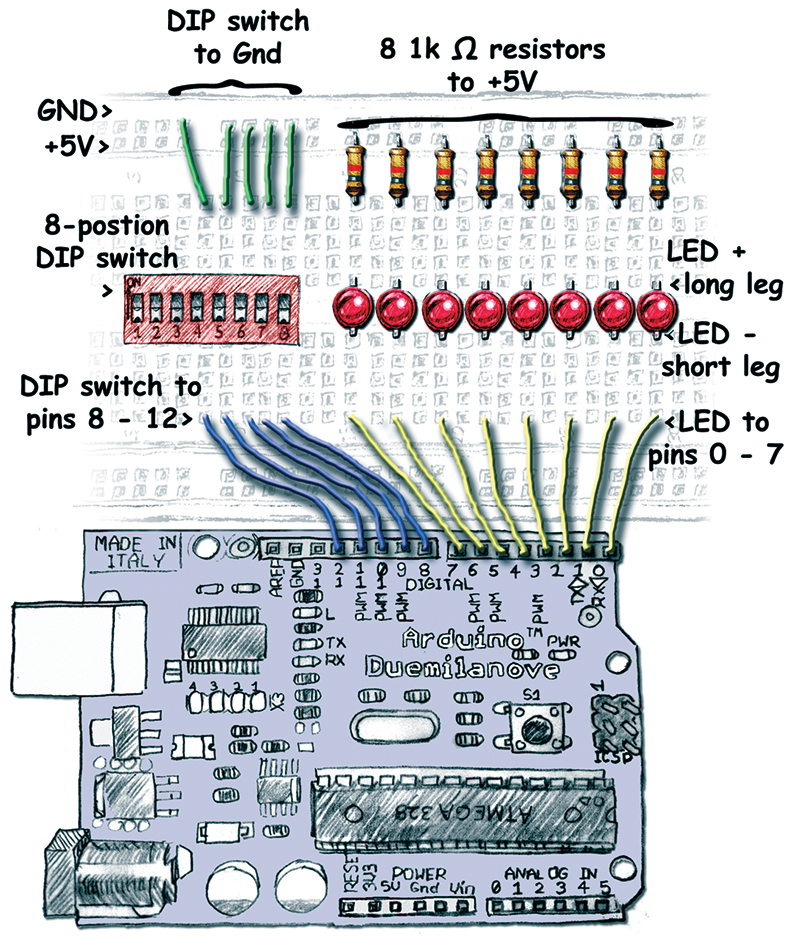
FIGURE 6. Testing digitalio using the Arduino.
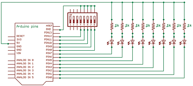
FIGURE 7. Arduino pins for DIP switch and LEDs.
Digital I/O Electrical Characteristics
After getting our toes wet with some elementary software, let’s go off the high board and look at the hardware. Microcontroller ports (like real ports) are limited in how much protection they can provide and like a seaport, when a hurricane comes along the port can get swamped. In the good old days, you were advised to wear static protection when messing with ICs to prevent static electricity from entering the pin and zapping something important inside the chip. Nowadays, devices like the AVR have input diodes (Figure 8) that help protect them.
The first thing to note is the diodes connecting the pin to Vcc and GND. These help protect the pin from things like you walking across a wool carpet on a dry winter’s day and then gently touching your micro — ‘snap!’ — exposing it to a few thousand volts of static electricity. There is also an input capacitance associated with the pin that you might have to deal with in your circuit design, though it is small and I usually ignore it. Also, there is a pull-up resistor that we can activate to connect the pin to VCC through about 20K ohms — more on this later. Figure 9 shows more detail.
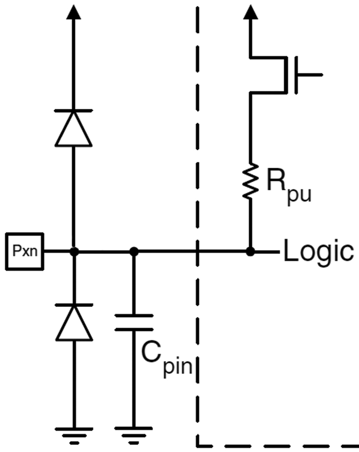
FIGURE 8. Pin equivalent circuit.
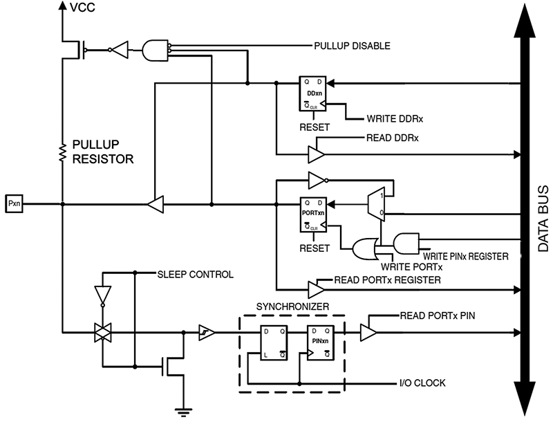
FIGURE 9. Pin schematic.
We know that for something to be digital in our microcontroller binary logic sense it can have two states that can be thought of as true and false, high and low, 1 and 0. From the simplicity of these two states flows the entire digital revolution — arguably the most significant change in human history — so it is kind of fun to be able to actually get our hands on these magical ‘states’ in the form of little silver pins hanging on the sides of our AVR black box. We use digital input when we want to sense an event in the real world such as a button state. We use digital output when we want to change something in the real world such as lighting an LED. [And that is pretty much all we do with microcontrollers: We sense and change things.]
Hysteresis?
In our case, this refers to the concept that we must have above a certain voltage to generate a 1, and below a different lower voltage to generate a 0. For a five volt AVR, we considered any voltage above three volts to be 1, high, or true, and any voltage below two volts to be 0, low, or false. What about voltages between two and three?
If a voltage falls below two, then the pin indicates low even if the pin immediately rises to 2.1 or 2.9999. It has to go all the way to three to change the pin to high; then if it drops below three, the pin continues to indicate high until it falls below two volts when it changes to low. This is called hysteresis and is a great feature because it allows us to measure signals with some noise on them.
Imagine a signal that is slowly dropping from three to two, but has a bit of ± 0.2 volts high frequency chaos jumping around. If the pin state changes from high to low and low to high at exactly two volts, then you’d see the pin toggling like crazy, going off and on due to the noise while the real signal (the average of all that noise) we are interested in takes its own good time falling below our threshold plus the noise level. We might read a thousand transitions while the signal voltage falls the extra 0.2 volts noise needed to get completely below the transition threshold.
Logic Input/Output Voltage Levels
In the discussion above, I said that for 5V a value above three was a 1 and below two was 0; that was a simplification to help understand the concept. Looking at the ATmega328 datasheet section 29.8.9 Pin Threshold and Hysteresis, we see that for the I/O pin to read 1 when the Vcc is five volts, the input voltage level should be above about 2.6 volts. For the pin to indicate 0 with a Vcc of five volts, then the input voltage should be below about 2.1 volts. So, using five volts we have a hysteresis of about 0.5 volts. At a Vcc of 3.3V, these values would be above about 1.6 volts for a 1 and below about 1.25 for a 0, with about 0.35 volts hysteresis.
Why do I keep saying ‘about?’ That is so you won’t memorize these figures and think you know how to generate a 1 or 0 on an input pin. Ask yourself: When have you ever gotten exactly five or 3.3 volts for Vcc? What if you are using batteries and you’ve got 3.2 volts one day and 2.7 a month later? What I’m saying is that you need to consider these thresholds and hysteresis values as ballpark figures for your application. Make sure you’ve got some extra voltage if you want to be certain you’ve got a 1, and that you take it down farther than the indicated low to assure that you are getting a 0.
The Arduino website [http://arduino.cc/en/Reference/Constants] states that for a digital input high you need to provide greater than 3V, and for a digital input low you need to provide less than 2V. While this is certainly true for the standard 5V Arduino, it isn’t true for those Arduinos that use lower voltages such as the 3.3V models. For these, the 3V high will work, but for the low you really need to provide less than 1V. You might think that this would be simple, but look no further than the thread I started on AVRFreaks to see that it isn’t.
If you look at the datasheet section 28.2 DC Characteristics, you get some absolute maximum and minimum electrical parameters to work with. The datasheet Table 28-1 shows the maximum input low:
- For Vcc = 1.8V–2.4V maximum input low is 0.2*Vcc.
- For Vcc = 2.4–5.5V maximum input low is 0.3*Vcc.
Minimum input high:
- For Vcc = 1.8V–2.4V minimum input high is 0.7*Vcc.
- For Vcc = 2.4 – 5.5V minimum input high is 0.6*Vcc.
From which we can calculate:
- For 1.8 volts, the maximum input low is 0.2*1.8V = 0.65V.
- For 1.8 volts, the minimum input high is 0.7*1.8V = 1.26V.
- For 5.5 volts, the maximum input low is 0.3*5V = 1.65V.
- For 5.5 volts, the minimum input high is 0.6*5V = 3.3V.
Okay, this is getting to be way too much so let’s promulgate a rule of thumb that applies in all cases: take 0.2*Vcc for low and 0.7*Vcc for high. If this is too restrictive and you want to make the reasonable assumption that your five volt system won’t fall below 2.4 volts, then you can use a narrower range of 0.3 Vcc and 0.6 Vcc which for five volts gives you above 0.6*5 = 3V for a high, and below 0.3*5 = 1.5V for a low.
What about digital output? Well, that is a bit clearer but with the complication that it depends on the current it has to provide to the output circuit.
- Output low for 5V at -20 ma is 0.9V or less.
- Output low for 3V at -10 ma is 0.6V or less.
- Output high for 5V at -20 ma is 4.2V or more.
- Output high for 3V at -10 ma is 2.3V or more.
We can see that these digital output high and low values will work with the digital input pins, but if you are using them to drive something other than an AVR compatible digital input, then you might have to take a look at the datasheet.
Next time, we are going to take a deeper look at digital input and output, confronting the datasheet, examining the registers, and learning how to do digital I/O in ordinary C. NV
If you just can’t wait and want to get a leg up on all this serial stuff and real C programming for the AVR, then try my C Programming book, Butterfly projects kit, and the Virtual Serial Port Cookbook from the Nuts & Volts shop.