
If you've ever dreamed of building your own MIDI device but didn't want to get your hands dirty with assembly language, complex programming circuits, or microcontroller architectures which make your head swim, then you've come to the right place! Here's a nifty project which will convert MIDI on and MIDI off signals to logic levels through either eight independent gate or trigger outputs. Musicians will find it useful for such things as firing analog music synthesizers, clocking drum sequencers, and synchronizing recorders. With the addition of relays or opto-isolators, it could also form the heart of light shows, home automation rigs, and the like. Best of all, the whole shebang can be easily implemented and customized since the brain of the unit is the beginner-friendly PICAXE 28X2 microcontroller. As we'll see, no expensive or complicated equipment is required to burn the program into memory, putting the project within easy reach of all.
If you're new to the world of microcontrollers, then here's the deal. With a system like this, you'll be able to write a program in a language closer to what humans use (that's Basic here), but be able to convert it to something the microcontroller likes (that's machine code). Burning simply means storing the machine language equivalent you've just created inside the microcontroller; this puts the chip through its paces.
Versatility is achieved by making either gate or trigger outputs available at the flip of a switch. In gate mode a MIDI on signal brings an appropriate output high, leaving it on until a corresponding MIDI off is detected. On the other hand, in trigger mode a MIDI on signal pulses an output for around 10 milliseconds, with MIDI off being ignored.
As two simple examples, a gate is perfect for controlling a synthesizer envelope generator, while triggers are at home firing analog drum voices or perhaps punching in a recorder on the down-beat. If this sounds interesting, then read on to find out just how simple it all is.
What the PICAXE Provides
Before getting into the details, let’s conduct a general overview of the PICAXE 28X2 chip and see what makes it so useful for this project. First, there are ample input and output ports to handle all of the switches, LEDs, and gates or triggers. In particular, we’ll be using four input lines and 17 output lines. A built-in serial interface will easily handle the MIDI signal, which is also serial in nature and runs at 31.25 kHz.
Then, there are the usual things such as resonator inputs, a reset line, and a programming interface.
Inside the chip, you’ll also find a huge amount of program space, plenty of variables in RAM, and even some general-purpose EEPROM for holding data after power-down. This truly is an all-in-one unit, and only requires some simple buffers to complete things. If you’ve peeked ahead at the schematic or even the printed circuit board (PCB) parts placement guide, then you were probably already struck by just how condensed the complete MIDI to logic controller circuit really is. With our quick reconnaissance out of the way, let’s dig in more deeply and see what makes the circuit tick.
How It Works
Refer to Figure 1 which shows the schematic. There are eight main outputs at pins 21 through 28 on the PICAXE 28X2. Since we want to connect these to real world devices, we’ll buffer them. Check out pin 28, for example, which drives an inverter configured around transistor Q8. This gives plenty of current for whatever application you have in mind. Note too that the output impedance is 1K which is a typical electronic music standard, as is the +5V level.
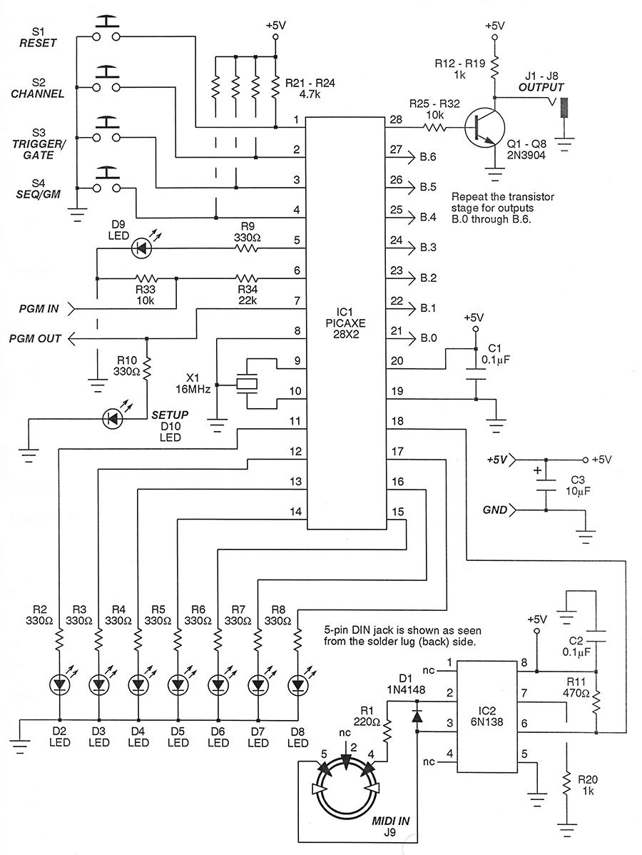 |
| FIGURE 1. Schematic of the MIDI to logic controller. |
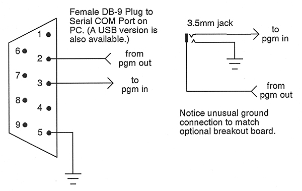 |
| FIGURE 2. Programming cable interface for the PICAXE. |
The buffers are repeated for a total of eight outputs. These are the lines comprising port B. For greatest versatility, only the software needs to be changed to make these either gate or trigger outputs. Again, when in trigger mode the pulse width will be somewhere in the neighborhood of 10 milliseconds. Remember, the width is irrelevant here; it’s the timing of the leading edge that matters.
We’ll want a visual indication as to which outputs are being fired. So, let’s turn to port C and use pins 11 through 17. The PICAXE is able to directly drive the LEDs via the 330Ω resistors, R2 through R8.
We just saw in the previous paragraph that the outputs in trigger mode blip with a short pulse width. This is really too brief for the human eye to pick up on decently, so we’ll let the firmware take care of making sure the corresponding LEDs have an on-time of about 50 milliseconds.
Counting pins, you’ll notice that we’re one short on the LEDs. That’s because pin 18 in port C must be used for the serial MIDI input. No big deal; we’ll just impose on pin 5 (which is actually port A.3) to provide the full complement.
The firmware keeps it all straight, so now we have eight outputs and their corresponding eight LEDs under control.
One final LED D10 indicates whether the unit is currently idle, holding in display or setup mode, or actually active and ready to translate the incoming MIDI stream.
Let’s take on the switches next. There are four pushbuttons that handle all of the input activity. S1 is a typical reset switch. Normally, reset pin 1 is held high by R24 but briefly pressing the button brings it low, forcing the chip to start from a known condition.
We’ll do some other clever things with this in just a moment.
S2 allows you to set or confirm the MIDI channel. The MIDI standard provides for 16 possible channels, and any one of these may be set as a default which is then stored in EEPROM. Additionally, it is possible to coerce the device to operate in Omni mode, in which case it responds to data from any of the 16 channels. The user instructions in sidebar 1 will make it clear how to set the channel.
Pushbutton S3 is used to toggle between the gate and trigger modes alluded to earlier. Again, the default is saved in EEPROM.
The last switch S4 offers a unique feature of special merit in drum applications. Part of the MIDI protocol allocates some 40 different percussive instruments to note numbers. This aspect is known as General MIDI, or GM for short.
If, in fact, you are playing back a drum part saved as a MIDI file, it is likely the drums (bass, snare, tom-tom, etc.) are designated by the GM note numbers. Well, in GM mode this circuit will automatically translate these and route them to the correct drum outputs.
The alternative is called Sequential mode. In this case, the eight outputs are mapped consecutively to middle C on up to middle G. This makes it easy to play the drums from a piano type keyboard since they are all next to each other on the scale. (In GM mode, the drums are scattered all over the place.)
As a rule, I use Sequential mode for my own compositions, but employ GM mode when playing back someone else’s MIDI file. In either event, switch S4 accommodates things nicely.
Nothing has been said yet about how the serial data makes it into the PICAXE. Let’s chase that down now. A MIDI cable (from a PC or Mac running sequencer software, for instance) connects to jack J9. This goes to optocoupler IC2, configured in a standard way to convert the current loop input to a digital signal. The inputs are at pins 2 and 3 of the optocoupler, while the output is at pin 6. The conditioned digital signal then feeds pin 18 of the PICAXE. This is port C.7. Recall that we have no choice in this, and must use this pin for serial input.
The PICAXE 28X2 is quite versatile in how it can be clocked. In this application, we need all of the speed we can get, so we’ll put it under control of ceramic resonator X1. This is a three-pin device, with the middle pin grounded and the other two going to pins 9 and 10 of IC1.
A resonator rated at 16 MHz is specified here, but note that a phase-locked loop within the PICAXE actually multiplies this by four. Hence, the chip is running at a speedy 64 MHz, which isn’t too shabby!
So, what about the programming? As mentioned earlier, that’s a snap with the PICAXE series and it is also quite inexpensive to set up. You’ll notice pins 6 and 7 are indicated as program lines on the schematic.
R34 is a current-limiting resistor on the input, while R33 is a pull-down to keep the sensitive input line from floating. The free PICAXE manual gives the details of how to program the chip (it’s easy), but see sidebar 2 for a quick look.
To complete our survey of the circuit, observe that pins 8 and 19 of IC1 are grounded, while pin 20 is the +5V line. Decoupling capacitors are used throughout.
An Easy Build
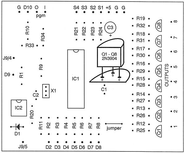 |
FIGURE 3. Parts placement guide.
|
Constructing the MIDI to logic controller couldn’t be simpler. After all, the PICAXE 28X2 bears most of the burden. I was able to whip up a PCB design in a short evening and had the thing etched and drilled by the following morning. Since this is a fairly pedestrian layout, we can readily get by with single-sided.
I used Press ‘n Peel to transfer the artwork and a small travel iron to bake it on. The PCB artwork is available at the downloads link below, while Figure 3 gives the parts placement guide. But really, the circuit is so straightforward that it could just as easily be wired by hand on perfboard.
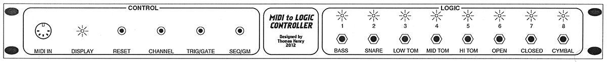 |
| FIGURE 4. Front rack panel layout. |
Everything in my studio is rack-mounted, so that’s what I went with here. Figure 4 shows the front panel design. This is a standard 1U panel, weighing in at 1-3/4 inches by 19 inches. The circuit board mounts behind the panel on small angles. Figure 5 is a snapshot of the completed undertaking.
|
| FIGURE 5. The completed uit, ready to slip into a cabinet. |
I wanted to leave the programming jack in place to make it easy to update the firmware later if needed. If you look carefully at Figure 5, you’ll see it on pigtails hanging off the back of the board. The wiring of Figure 2 was used.
Since this is an unusual arrangement (employed merely to maintain compatibility with my PICAXE breakout board), it is important that the programming jack not be panel-mounted unless it is an insulated type.
Firmware, Latency, and Jitter
The time has come to discuss the firmware. You’ll find the complete source code in Basic at the article link. The code has been extensively documented, so not only should it be a snap to understand but customizing it for your application should be a breeze. Here are some general comments to guide you along.
As you probably know, MIDI (being serial in nature) requires a lot of activity in a very brief period of time. As a consequence, getting the MIDI to logic controller up to speed was a real battle. All of the prototypes essentially worked from the get-go, but early versions suffered from latency and jitter. Latency is a lag time between receiving a command and executing it. Jitter occurs when the latency varies over time.
So, here’s the deal. This unit has an incredible amount of work to do in short intervals. The first step was to bump the microcontroller’s master clock to 64 MHz. Next up was to optimize the code. Since the PICAXE uses a tokenized Basic language (notoriously slow by any standards), it was necessary to break all the rules of good structured programming and instead just focus on speed.
Also, there is tons of program space available, so I made no attempt to minimize the size of the program — again going instead for fast execution.
My motto was (lifted from an old movie) “waste anything but time.” So, as you read the code you’ll see just how profligate I was with program space, but it was for a legitimate purpose.
Actually, gate mode has very little overhead associated with it and never gave any grief. It was trigger mode that really kept my nose to the grindstone. The code provides a clue on how I finally distributed the trigger updates over time to spread out any noticeable jitter error.
One final thing helps. In a real world situation, it is common to use a MIDI filter before any unit (commercial or otherwise) in a setup. This is to ensure that all of that mixed bag of signals coming down the pike be delivered only to the devices really needing them.
Most people — including me — use the wonderful and free program MIDI-Ox in the usual course of things. (You can download it from www.midiox.com). With the filter removing all the chaff not required by the MIDI to logic controller it was possible to greatly simplify the code, hence speeding things up appreciably.
Now it no longer needs to be looking for channel numbers, checking Omni mode, passing over system real time messages, etc.
In short, the final code simply responds to MIDI on and MIDI off messages, leaving the filtering of all else to MIDI-Ox (or something similar). With that in place, very rapid sequences can be played with no objectionable jitter.
When you download the code, you’ll see there are two versions. One is the stripped down variant just described. However, if you’d like to try the full-blown rendering with the built-in filtering, that’s there, too.
I originally took on this project as a challenge. I had read so many comments on the Web bemoaning the “fact” that the PICAXE just isn’t fast enough to do MIDI that I wanted to see for myself.
It took a month of daily experimenting and hair-pulling, and I almost gave up more than once. Truthfully, though, while this circuit pushes the PICAXE to the limit, it really does get the job done and then some.
I hope you enjoy it, and more importantly I hope it helps you to create some new music! NV
PARTS LIST
|
| ITEM |
DESCRIPTION |
ITEM |
DESCRIPTION |
| All fixed resistors are 1/4 watt, 5% values. |
Semiconductors |
| R1 |
220Ω |
D1 |
1N4148 diode |
| R2-R10 |
330Ω |
D2-D9 |
Red LED |
| R11 |
470Ω |
D10 |
Green LED |
| R12-R20 |
1K |
Q1-Q8 |
2N3904 NPN transistor |
| R21-24 |
4.7K |
X1 |
16 MHz ceramic resonator |
| R25-R33 |
10K |
1C1 |
PICAXE 28X2 |
| R32 |
22K |
1C2 |
6N138 optocoupler |
| All capacitors are 16V or better. |
Miscellaneous:
Printed circuit board, IC sockets, front panel, LED holders, wire, etc.
The PICAXE 28X2 is available from SparkFun Electronics or RobotShop, among others.
www.sparkfun.com
www.robotshop.com
All other parts are commonplace and available from general suppliers.
|
| C1, C2 |
0.1 µF disc |
| C3 |
10 µF electrolytic |
| Other components |
| J1-J8 |
1/4" phone jack, N.O. |
| J9 |
Five-pin DIN jack |
| S1-S4 |
Momentary SPST switch |
MIDI to Logic Controller User Guide (Sidebar 1)
There are four modes of operation. In Run mode, the unit responds to MIDI data — its primary job. In Display mode, you can confirm the stored defaults. In Set mode, you can revise and store those defaults. Finally, in Test mode the unit will output three different test patterns — useful for setting up your patches in a home studio or on stage.
At power-on reset, the unit comes up in Run mode (LED D10 off) using the defaults currently stored in EEPROM. These may be changed and stored by the procedures listed below.
To turn on Omni or select a specific channel:
- Simultaneously press both the Reset and Channel buttons.
- Release the Reset button. The unit enters Set mode.
- The LEDs begin by performing a quick chaser effect, indicating Omni on. If this is what you desire, then release the Channel button. Otherwise, continue to hold that button and the LEDs begin to flash.
- Counting the flashes, release the Channel button after the desired channel number has been indicated (1 through 16).
- The unit now enters Display mode which is described later (LED D10 on).
To toggle Trigger/Gate mode:
- Simultaneously press both the Reset and Trigger/Gate buttons.
- Release the Reset button. The unit enters Set mode. The LEDs will show the new mode using a dot-dash code. They will flash three times rapidly to indicate Trigger mode (a dot) or give one long flash (a dash) to indicate Gate mode.
- The unit now enters Display mode (LED D10 on).
To toggle Sequential/GM mode:
- Simultaneously press both the Reset and Sequential/GM buttons.
- Release the Reset button. The unit enters Set mode. The LEDs will show the new mode using the dot-dash code described above. A dot means Sequential mode, while a dash means GM mode.
- The unit now enters Display mode (LED D10 on).
To confirm your settings:
- You may confirm your settings in Display mode (LED D10 on).
- Press Channel. If Omni mode is on, the LEDs will do a quick chaser effect. Otherwise, all LEDs will flash the number of the currently selected channel.
- Press the Trigger/Gate button. The LEDs will indicate the mode with the dot-dash code described earlier.
- Press the Sequential/GM button. The LEDs will indicate the mode with the dot-dash code described earlier.
To play a test pattern:
- While in Display mode, press a pair of buttons, then release both.
Channel + Trigger/Gate - Test Pattern One - One at a time
Channel + Seq/GM - Test Pattern Two - All outputs at once
Trigger/Gate + Seq/GM - Test Pattern Three - Drum pattern
- The unit will begin playing a test pattern in Trigger mode.
- Press Reset to quit the test pattern and go to Run mode.
- Otherwise, press any other button to quit the test pattern and return to Display mode.
To exit Display mode and begin Run mode:
- Press the Reset button. LED D10 will turn off and the unit is now ready to receive MIDI data.
|
Programming the PICAXE 28X2 (Sidebar 2)
In the not too distant past, burning a program into a microcontroller was a genuine bearcat for the newcomer. First, there was the business of building a programmer (since commercial units were either priced out of range for the DIYer or simply not available). Then, there was the seemingly infinite learning curve to ascend. Assembly language had to be mastered, and a nontrivial amount of hours spent cracking the hard nut of cross-assemblers. The design cycle was slow and tedious, requiring all sorts of cable switching, yanking parts out of sockets, and re-assembling the code each time a problem was found.
That's all a bad memory now thanks to the PICAXE family of microcontrollers. Creating and burning a custom microcontroller couldn't be simpler, and even better is the fact it can be accomplished on a limited budget. Here's how to get started.
Your first step should be to acquire the PICAXE manual. This is free of charge and can be downloaded from the manufacturer's website at www.picaxe.com.
Next up would be to get the PICAXE programming editor and install it on your home computer. Again, this is free of charge even though it is an exceptionally well-written and easy-to-use piece of software. You'll also find it at the PICAXE site.
No complicated burning hardware is required, just a cable! I employ a homemade RS-232 version I tossed together for less than $4. If you're using the official PICAXE breakout board for development on a breadboard like me and want to stay consistent with it, then connection is made by means of a stereo 3.5 mm plug and jack. If that's what you're using, then note the unusual connections indicated in Figure 2. Commercial cables manufactured expressly for the PICAXE are also available and come in either RS-232 or USB flavors. Choose whichever matches your home computer. For example, a couple variations are available at SparkFun Electronics, among other dealers. For details, go to www.sparkfun.com.
If you've been following NV author Ron Hackett's column here over the past several years, then you already know something about programming the PICAXE. If you're new to it all and would like some more background on how to get started, then be sure to look into his initial entry in the December 2007 issue.
|
Downloads
MIDI to Logic Controller Download
Source Codes & PCB Pattern