Even in this day and age of highfalutin' audio electronics, a new guitar still has a non-zero probability of sounding pretty "blah" no matter how good the pickups are. It may have a weak low end response, or perhaps the treble setting is dull. Maybe it doesn't offer much variation in tonal quality overall. This article describes a retrofit you can make that will give your guitar the controls it deserves. Even the most plain Jane instrument leaps alive with a full range of bass, mid, and high end color. Best of all, it does it quietly; noise, hum, and hiss are simply not an issue thanks to several tricks explained here.
The Problem with Passive
To better understand the value of what’s coming up, let’s see how things are handled in a stock unit. The controls on a typical two-pickup electric guitar are often passive in nature (Figure 1).
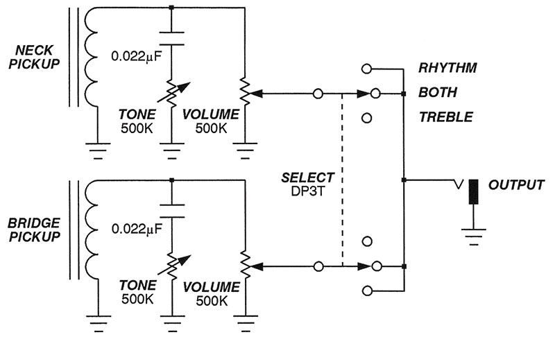
FIGURE 1. Passive controls on a typical electric guitar.
The capacitors shunt higher frequencies to ground, while their series potentiometers vary the amount of this action. Clearly, the most you could hope for with such a simple affair is the ability to gently roll off the treble response at about –6 dB/octave.
The effect is so feeble that many guitarists simply leave the tone controls at full resistance and alter the sound on their amplifiers. Completing the circuit, two additional potentiometers directly parallel the pickups, providing control over the volume. In general, passive tone controls like this have a low input impedance which can load down the pickups appreciably. This typically results in an attenuation of the higher frequencies, yielding a sound lacking sparkle or brilliance.
To lessen this effect, 500K potentiometers (a fairly high value indeed) are used throughout. This then raises the output impedance of the circuit, giving less than optimal results when driving the audio cable and amplifier. Actually, it all gets quite complex with other matters such as signal-to-noise figures, RF interference, and even the capacitance of the connecting audio cable complicating the issue.
In any event, the result is usually a poorer tonal response than we’d hope for even with the controls open full tilt. So, we have several problems to overcome. Passive circuitry like this: tends to load the pickups down; has a high output impedance less than ideal for driving the amp; and offers no more than a –6 dB/octave cut, which isn’t very inspiring.
Enter the Active Controls
Pretty clearly, the solution lies in internal active electronics. Commercial affairs didn’t appeal to me because of the price, and a search of previous DIY projects failed to turn up circuits with the features I desired. So, I decided to go it alone by starting from scratch.
What resulted is a tiny bit of circuitry fitting completely inside the electric guitar. It offers a whopping 15 dB of both cut or boost in three separate bands. Many people think of emphasizing a frequency range to be the touchstone, but actually the deep reductions possible with this unit are just as important. It's often the case that pickups on their own emphasize the midrange which (to my ears) yields a muddy result. With this circuit, it is possible to flatten out the response giving a fuller sound at the two extremes. Of course, with multiple bands, it’s possible to create all sorts of tonal mixtures right from your fingertips.
The benefits don’t stop there, however. Even if you ran this device flat (the bass, midrange, and treble controls set to their midpoints), your guitar would still sound more alive. The reason for this is that the pickups are now fully buffered. Loading and attenuation of the highs are nothing more than memories.
Moreover, the output has a very low impedance, allowing you to drive any amplifier or effects device without losing crispness. Of course, this is also a preamplifier, which can boost the signal and may prove useful for overdrive applications, among other things. If this all sounds appealing, then let’s get into the circuit details.
A Look at the Circuit
Figure 2 shows the schematic for the active tone controls.
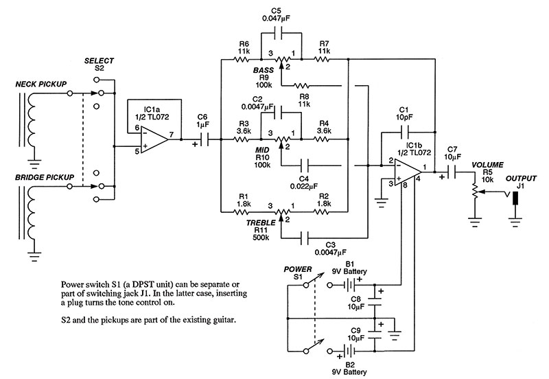
FIGURE 2. A three-band internal equalizer.
We’ll move the pickup switch to the input of the rig now, which allows us to buffer any combination selected; compare the location of the switch in Figures 1 and 2 to see this. The wiring of your guitar may change, but you shouldn’t have to drill any new holes or leave old ones unused. (Many electric guitars have four potentiometer holes with an additional hole for the pickup selector switch).
The pickups are buffered by IC1a. Recall that the non-inverting input of an op-amp sports an extremely high input impedance. So, now instead of a 500K pot bridging the pickups as in Figure 1, we have something on the order of many megohms doing so. In effect, we have completely unloaded the pickups, permitting every natural frequency component to pass with ease.
The buffered pickups are then capacitively coupled by C6 to the remainder of the circuit which implements a three-band EQ. The basic topology for this comes from a manufacturer’s datasheet, Audio Handbook (Santa Clara: National Semiconductor Corporation, 1977), pp. 2-44 through 2-49, edited by Dennis Bohn. The frequency-determining components cluster around potentiometers R9, R10, and R11 which are the bass, midrange, and treble controls, respectively.
You’ll note that the entire three potentiometer structure is in the feedback loop of IC1b. As we’ll see in just a moment, it isn’t necessary to understand the mathematics of this circuit in order to customize it. If you’re interested, the datasheet mentioned gives the details of the derivation. By the way, the only purpose of capacitor C1 is to suppress spurious supersonic oscillations or RF interference.
Finally, the output is AC coupled by C7 to volume control R5. By using capacitive coupling here, any small DC offsets are blocked from hitching a ride to the volume pot, which typically results in scratchy noise as the control is rotated. I suppose it would be possible to run this affair on a single battery with some additional components, but I decided to go with two for several reasons: There’s more headroom, even with all the boost available; clipping is never an issue; most op-amps perform better on a dual supply; a single supply requires additional components; and in any event, the two batteries last darn near forever since this is a low current affair.
Personalizing the Frequency Response
Let’s get serious about investigating what you can expect from the tone controls. When I first set about this project, I spent many hours pondering exactly how I wanted my axe to perform. I decided that my goal was to attain a full-bodied sound with decent control over the bass, midrange, and treble, but not really get into wild special effects. I next ran repeated SPICE simulations to see how the controls would interact. Don’t kid yourself. A three-band circuit like this is going to lead to some incredibly messy and difficult equations on paper. The only reasonable approach nowadays is to model the behavior on the computer before committing
The values shown in the schematic of Figure 2 are those from the original datasheet mentioned earlier, and they worked very nicely on my Gibson Les Paul Standard. On the other hand, I ended up tweaking various values when I built another version for my less expensive Epiphone guitar. When the three controls are centered, the response is essentially flat, as the computer simulation software will confirm (more on that in a moment). Figure 3 shows what happens when you cut or boost the bass, midrange, and treble.
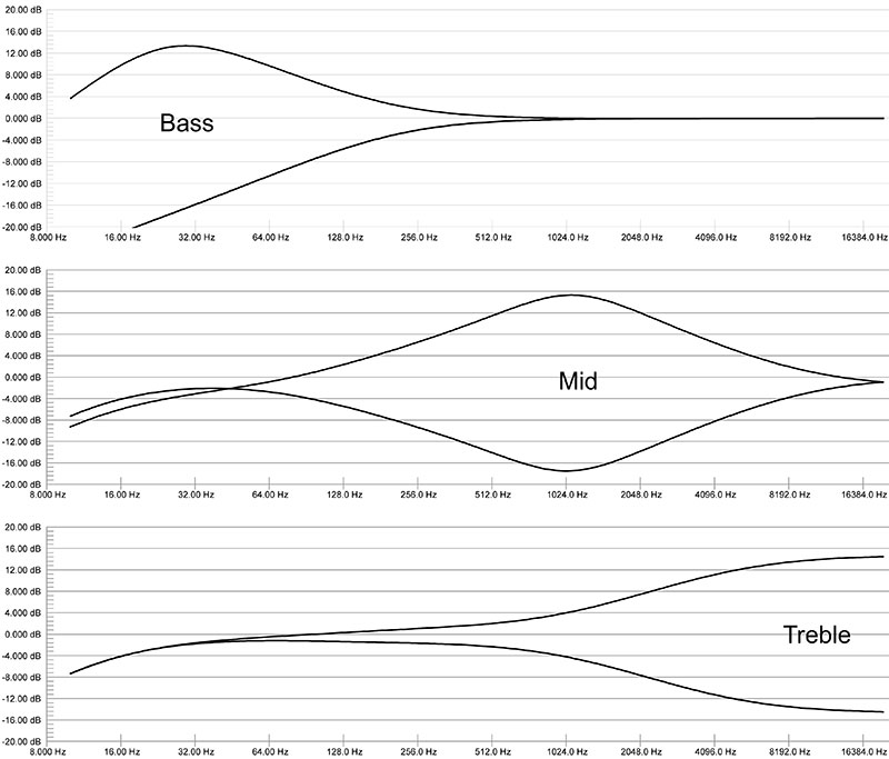
FIGURE 3. Response curves for the active tone controls.
The vertical axes are measured in decibels, while the horizontal axes are laid out in octaves (each tick mark represents a doubling of frequency). As you can tell from the curves, this circuit offers more than you’d ever find in the passive controls of the typical electric guitar.
I also ran checks on how the three bands work together. I essentially tried every combination of boost or cut for each of the bands in pairs, and then in trios. Don’t feel obligated to stick with my choices. Altering the response is as simple as changing the capacitor or resistor values around any of R9, R10, and R11.
In any event, the basic topology (and hence the printed circuit board; PCB) remains unchanged, so you can go with any option you want. Now’s your chance to personalize things! Do what I did — run the simulation software to arrive at values you like best.
Getting Ready to Build
So, we now understand the basics of the circuit and presumably you’ve arrived at some component values to give you the response you’re after. Electronically, this is an easy project to construct but putting it inside your guitar takes patience, care, and attention to detail. I’ll explain the steps I took (which worked out remarkably well, I must say), but you’re on your own here. You’ll have to decide if you have what it takes to work neatly on an instrument you love. That said, here’s what I did.
The first step was to gut the guitar of the existing passive circuitry. As mentioned earlier, I’ve actually done this on two guitars now. To make the discussion specific here, I’ll show you how it went on my road-worn but trusty Gibson guitar. Similar steps should apply to other instruments.
I began by opening up the three cavities housing the existing controls, the pickup selector switch, and the output jack. I carefully desoldered the pots, switch, and jack. The first step was to rewire the switch as indicated in back as in Figure 2. I made it a point to label the various wires running throughout the channels in the body of the guitar as I went along. The pots were set aside altogether since I opted to start over again with four new and better quality ones. (I did save them in case I ever wanted to revert to stock again.)
The main thing here is to clean out the cavities completely, which will probably entail vacuuming the sawdust left by the manufacturer (I’m not kidding). Incidentally, now’s the time to work out the replacement potentiometer business. Both Jameco and Mouser had the knurled shaft pots I needed for my two guitars, but you might have to scout around depending on your make. The main thing here is that I only took advantage of existing holes; once complete, there was no change to the external appearance of either instrument.
Now comes an aspect that’s just as much a part of the success of this project as anything. Most guitars are simply wood and little more. Thus, the cavities housing the controls, switch, and jack are not shielded and open to attacks from 60 cycle hum.
To save money, guitar makers get around this by running a wire from the metal bridge of the guitar to ground. The general idea is that when your body is in contact with ground through the strings and bridge, it acts as a shield in some strange sort of way. (Don’t ask me how it works, but it does). I don’t know about you, but I don’t really like being a conductor. If hot and neutral to the AC supply of the guitar amplifier and the PA system, say, are flipped, then you’re really opening yourself up to a shock hazard. (You can probably tell I’ve spent some 20+ years of my life playing dilapidated ballrooms with substandard wiring.)
My solution was to completely remove the connection from the bridge to ground, and simply shield all inner surfaces with copper foil tape. So, locate the single wire coming from the bridge to the main control cavity, desolder it from ground, wrap it up, cover it with electrician’s tape, and poke it in an out-of-the-way spot. Don’t just clip it off in case you later discover you really do need it to avoid hum problems.
Next, using copper foil tape, completely cover the inner surfaces of the three cavities. The tape is conductive on both the front and back sides, so you can overlap things bit by bit with smaller pieces to blanket even the most curvy area. Figure 4 shows this in progress for the control cavity.
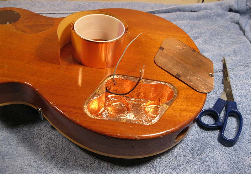
FIGURE 4. Shielding cavities with copper foil tape.
When you’re done, screw a solder lug into the wood so that it contacts the foil, and connect a single ground wire (from the output jack, say) to ensure each cavity is grounded.
Don’t forget to apply foil to the back side of the covers; you can also see this in Figure 4. Once the seals are in place, all of the pots, the switch, and jack are completely enclosed just as if you had built them within a metal box. I’m amazed at how well this all worked. I have no hum whatsoever, and best of all, will never have to worry about sparks from the lips again. You can seal up the switch cavity now, but leave the control cavity open since we still have to implant the electronics.
Bring On the Circuitry
Now comes the easy part. Building the active tone control is quite straightforward. Since this has to fit inside the control area along with four pots and two batteries, space is at a premium. For that reason, a PCB is the only way to go. Artwork is available in the downloads, while Figure 5 here shows the parts placement guide.
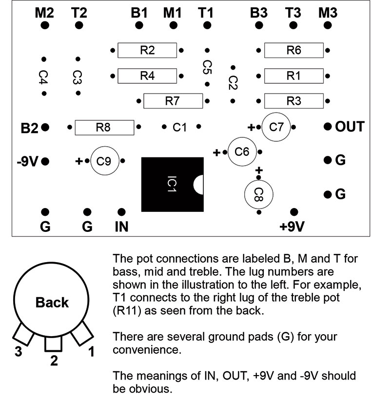
FIGURE 5. Parts placement guide and wiring details.
Be sure to check all electrolytic capacitor polarities carefully, as well as the orientation of IC1. The potentiometer wiring scheme is depicted there, as well. Notice too that the pot lugs are numbered on the schematic which helps keep you from wiring them backwards. Speaking of which, it makes sense to prewire the potentiometers as much as possible since the control cavity is fairly tight to be sticking a soldering iron into. Figure 6 shows the completed rig just about ready to go inside the guitar.
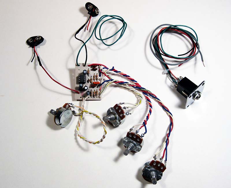
FIGURE 6. Prewiring components makes installation easier.
I haven’t said anything about the power switching yet. I think the neatest approach is to use a switching jack. This is a 1/4” phone jack which also includes an independent DPDT switch. When a plug is inserted, the switch part does its thing closing the connections to the two batteries, while the audio portion is free to pass the signal as usual. Figure 7 gives the details for the jack I used, but you should test yours with a multimeter in resistance mode to make certain you understand the pin configuration.
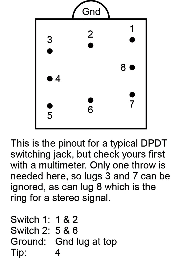
FIGURE 7. A switching jack turns the unit on and off.
Figure 8 shows the completed implementation just before sealing up the back.
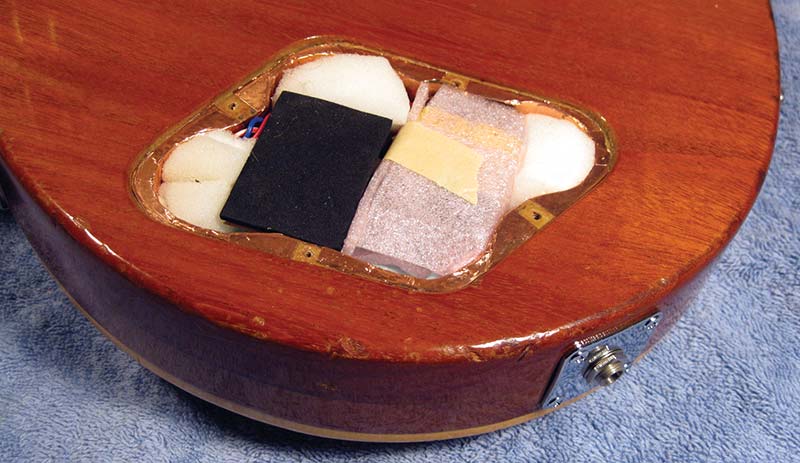
FIGURE 8. The job is done and ready to be sealed up.
That’s the PCB on the left, components facing downward, and with a piece of black foam covering the foil side. Next to it is a pair of batteries, wrapped in a piece of plastic sheeting and taped together as a block. The remainder of the cavity is plugged with pieces of foam rubber to keep things from rattling about. All in all, it is a nice, tidy, and snug fit.
I really took pains planning my moves (you should too), and didn’t try to do too much at once or while tired. Anyway, once the cover plates were back in place, it was impossible to tell outwardly that this guitar had become bionic in the meanwhile.
One final detail. The active tone controls give a flat response when in their central positions. This means that you’ve got to be able to find that setting easily. A neat solution is to use some nickel-plated knob indicators which are secured in place over the pot bushings by the pot nuts.
The pointers remain static while the numbering on the knobs register against them as the controls are turned. In my setup, when the bass, midrange, and treble controls are aiming at 5, then I know I’m at my flat reference point. Moreover, when the volume control is at 5 as well, I’m at the correct “normal” level for my system. The Parts List describes where you can locate the knob indicators and other items out of the ordinary.
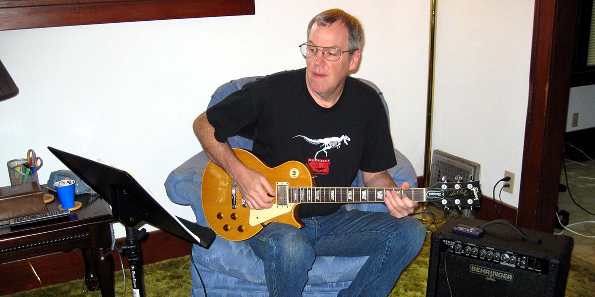
So, if Dullsville is the name of your guitar, consider resuscitating it with active tone controls. It takes care and planning to perform surgery on a valued instrument, but it really paid big dividends in my case. I hope it does for you too! NV
PARTS LIST
| ITEM |
DESCRIPTION |
| R1, R2 |
1.8K |
| R3, R4 |
3.6K |
| R5 |
10K linear potentiometer |
| R6-R8 |
11K |
| R9, R10 |
100K linear potentiometer |
| R11 |
500K linear potentiometer |
| C1 |
10 pF disc |
| C2, C3 |
0.0047 µF mylar |
| C4 |
0.022 µF mylar |
| C5 |
0.047 µF mylar |
| C6 |
1 µF electrolytic |
| C7-C9 |
10 µF electrolytic |
| IC1 |
TL072 dual op-amp |
| J1 |
1/4" phone jack, with DPDT switch |
| B1, B2 |
9V battery |
Fixed resistors are 1/4 watt, 5% values. All capacitors are 16V or better.
Miscellaneous
Printed circuit board, IC socket, battery snaps, copper foil tape, knobs, knob indicators, wire, etc.
Most of these parts are available from any number of electronics suppliers. The more unusual copper foil tape, switching jack, and knob indicators are available from Stewart-MacDonald (www.stewmac.com).