There are two schools of thought in the audiophile world on how to best achieve nirvana. One is to invest in huge power amplifiers and massive speakers in order to reproduce every nuance captured in a recording. The other school — more popular among the space — and financially-constrained, is to invest in low-power precision preamplifiers, amplifiers, and headphones.
Of course, if money is no object, it’s easy to spend $6K on a preamp, another $5K on a stereo headphone amplifier, and another $2K on headphones. However, as described here, starting at about $30 in parts for the core amplifier and a weekend of soldering surface-mount components, you can enjoy audiophile sound. In addition to a complete parts list with price and Digi-Key part numbers, as well as the schematic and printed circuit board (PCB) in ExpressPCB format (www.expresspcb.com), are posted on the Nuts & Volts website. This is an intermediate-level project that involves extensive use of surface-mount components.
Headphone Amplifiers
If you’ve built or reconditioned a tube-type preamp, it likely doesn’t have provisions for headphone output. At the other end of the spectrum, many modern audio players are designed primarily for headphone output, but they stress power or song capacity over output precision. That is, the headphone output from your MP3 player, when coupled with inexpensive ear buds or earphones, is significantly colored. The bass may be accentuated and the midrange diminished relative to the original recording, for example, because of the frequency response curves of the player’s amplifier and headphones. The Apple iPod and similar MP3 players provide a partial work-around for coloring by featuring built-in graphic equalizers.
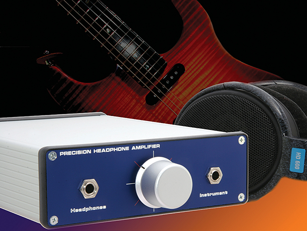
The first step to significantly increasing the quality of audio you hear from your high-end preamp or MP3 player is to use a pair of high-quality, over-the-ear, dynamic headphones. Higher-quality, precision earphones generally have a higher impedance (e.g., 100–300 ohms) compared to the standard 10-20 ohm ear buds that ship with players. Several manufacturers offer high-end ear buds as well, but, in general, it’s hard to beat the best over-the-ear variety. The next step is to take the line-out of your CD or MP3 player and use a low-power, high-precision amplifier to drive your dynamic headphones. The motivation for going through all this trouble is a precise, low-distortion reproduction system to hear an audio source as it was recorded. Headphone amplifiers are also popular among guitarists. If you play an electric guitar or electric bass, then you know the peril of practicing around friends and family with your 100 watt Marshall or Fender amp. Headphones are often the only option for musicians who practice in an apartment or dorm.
But do you need a precision headphone amplifier? It depends on your listening preferences and habits. Obviously, if you only listen to your iPod or portable CD player when you’re running or in the gym, then this project isn’t for you. Similarly, if you play metal or other highly distorted styles, then any headphone amp will probably do. However, if you listen to music at home or in the office and your tastes tend toward classical, jazz, or clean vocals, then you’ll probably appreciate the subtle difference a precision amplifier and a good set of headphones can make. One note of caution about this headphone amplifier: It’s capable of driving a set of headphones well above the normal listening levels. As such, if used inappropriately, it can permanently damage your hearing.
Options
Let’s say you’re convinced that building a headphone amp is a worthy project. What’s your next step? A common, inexpensive option is to use the ubiquitous LM386. The monophonic chip has a lot going for it: ruggedness; low cost; ability to work with a single-ended supply and the external component count is low — typically two or three capacitors and resistors for each channel.
The LM386 is fine for driving inexpensive headphones, but noise and distortion figures pale in comparison to what can be achieved with either a well-designed discrete component amplifier or — as with this project — a ‘precision’ headphone driver IC. Still, if your project budget is $20 or less, you can build a stereo headphone amplifier from the information contained in LM386 datasheets. However, if you long for a more substantial amplifier and aren’t intimidated by surface-mount components, then read on.
Design Goals
When I set out to design the headphone amplifier, I had several goals:
- The amplifier had to work with both my high-impedance tube preamplifier and with my Stratocaster electric guitar. In other words, the front end had to be flexible enough to accommodate sources with a range of input impedances.
- Low component count. This favored chips over discrete transistors.
- Modest amplification and power. The goal was to drive a sensitive set of dynamic headphones, not a speaker system.
- High-impedance headphone output. The circuit was designed for my Sennheiser HD 600 (300 ohm) dynamic headphones.
- Low noise and distortion. Noise and distortion figures as low as practical with off-the-shelf op-amps.
The schematic of the second generation design is shown in Figure 1.
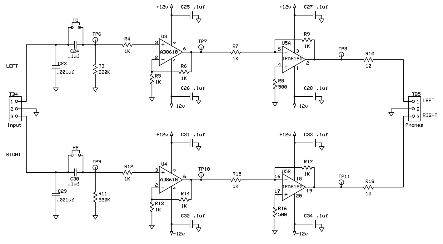
Figure 1. Precision Headphone Amplifier Schematic
In developing this design, I used component comparison tools on the National Semiconductor, Texas Instruments, and Analog Devices websites. I also searched the web for headphone amplifier schematics and design suggestions. The Headwize site (www.headwize.com) was particularly helpful, in that it offered several headphone amplifier designs and a library of technical papers. The forums on DiyAudio.com were also helpful. In the end, I selected the Texas Instruments TPA6120A2 precision stereo headphone amplifier chip and a pair of Analog Devices AD8610 op-amps as the major active elements of the precision headphone amplifier.
The schematic of the amplifier shows the straightforward, symmetrical design with two AD8610s each driving half of the TPA6120A2. Note that the positive and negative power supply leads are bypassed at the ICs, and that the input capacitors (C24 and C30) can be shorted if the input doesn’t contain a DC voltage. In addition — as per the datasheet from Texas Instruments, the output current is limited by 10 ohm resistors (R10 and R13) in series with the output of each channel.
The power supply (Figure 2) provides both +12 VDC @ 1A and -12 VDC @ 1A. As is often the case in audiophile equipment, the power supply is over-designed and more costly than the amplifier circuit proper. If you download the detailed parts list with Digi-Key part numbers from the Nuts & Volts website, you’ll see that the cost for power supply components is about $50.
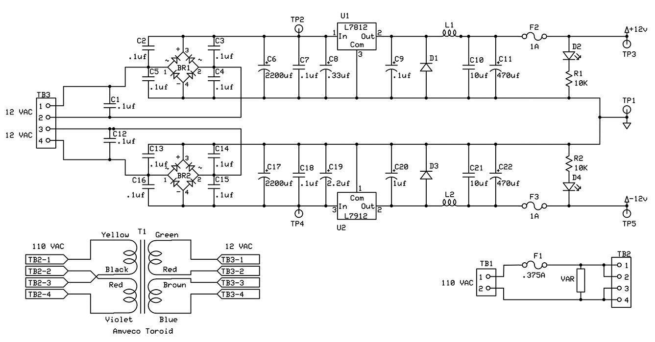
Figure 2. Precision Headphone Power Supply Schematic
In the first version of my amplifier, I followed a schematic on the web that took advantage of the separate supply lines to each channel of the TPA6120A2. However, I couldn’t hear or measure any difference in separation or noise when I substituted a single supply for the dual supply.
You can shave cost from the power supply by substituting a laminated core transformer for the toroidal transformer. For a given VA capacity, toroidal transformers are generally more efficient and produce lower intensity stray magnetic fields than laminated core transformers. You can also leave out the indicator LEDs (D2 and D4) and, if you must, the DC fuses (F2 and F3). A third option is to use a supply of your own design. Avoid a switching power supply, however, because it will likely generate audio noise.
Components
Following is the rationale for the components selected for this project, together with a discussion of component substitution options.
TPA6120A2
The Texas Instruments TPA6120A2, marketed as a high fidelity headphone amplifier, uses a current-feedback architecture with differential inputs and single-ended outputs. According to the product sheet, the current-feedback design results in low voltage noise, high open-loop gain throughout a large frequency range, and low distortion. As I noted earlier, the TPA6120A2 contains two independent amplifiers, each with its own voltage supply. The specifications for the TPA6120A2 include:
- 80 mW into 600 from a ±12V supply at 0.00014% THD + N
- Greater than 120 dB of dynamic range
- SNR of 120 dB
- Output voltage noise of 5 µVrms at gain = 2V/V
- Power supply range: ±5V to ±15V
- 1300 V/µs slew Rate
- Independent power supplies for low crosstalk
- Short circuit and thermal protection
The total harmonic distortion plus noise (THD+N), dynamic range, signal-to-noise ratio (SNR), and slew rate (the maximum rate of change of a signal at any point in a circuit) are excellent. For comparison, the THD+N figure for a National Semiconductor LM386 is 0.2%.
Although great specifications don’t necessarily translate to great sound, they do set a baseline for what is possible. See the Texas Instruments website (www.ti.com) for the official datasheet, application notes, and user guide for the TPA6120A2. More importantly, download the documentation on the TPA6120A2 evaluation module, which provides drawings of suggested component layouts and ground plane configuration. I used the ground plane configuration from the evaluation module as a model for the design presented here.
AD8610
The Analog Devices AD8610 is a surface-mount JFET input op-amp with low offset voltage and drift, low current noise, and low input bias current. Two of these wide bandwidth op-amps are used in the project as precision signal-level buffers. See Analog Devices website (www.analog.com) for the datasheet with detailed specifications.
In brief, the noise figure and slew rate of the AD8610 complement those of the TPA6120A2. Even so, feel free to substitute your favorite low-noise op-amp for the AD8610. Many op-amps are pin-compatible with the AD8610 and you should be able to use the existing component values. Why use a different op-amp? Some audiophiles claim to hear a difference in the audio produced by different op-amps — but I confess, I can’t detect a difference.
Passive Components
Resistors are not created equal. Ordinary thin film surface-mount resistors — while inexpensive — are noisier and less stable than metal film resistors. I suggest you use metal film resistors throughout the project. You might save a dollar or two by using thin film surface-mount resistors instead, but at least consider metal film resistors for the input circuit to the AD8610s. Resistor-generated noise is more noticeable when inserted early in the amplifier chain. Most of the capacitors used for the signal path are low-noise PPS film. You may be tempted to substitute less expensive ceramic capacitors for PPS film capacitors, but you’ll have better results with the film variety.
Connectors
The connectors used in this project are RCA jacks for audio input and 1/4 inch audio jacks for instrument input and audio output. The instrumentation input audio jack is a mono phone jack with transfer circuit that connects the inputs of the left and right channels together when a 1/4 plug is inserted into the jack. The only splurge item in the connector category is the set of gold and Teflon RCA jacks, shown in Figure 3. The connectors, available from DIYCable.com (www.diycable.com), are about double the price of what you can pick up from Digi-Key, but the higher quality is obvious. In addition, the Teflon insulators allow you to float the ground until the signal reaches the input of the amplifier or input attenuator.
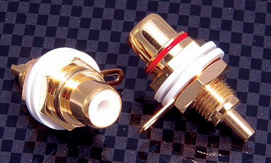
Figure 3. Gold And Teflon RCA Jacks
Potentiometer/Attenuator
The input circuit shown in Figure 1 is designed for a fixed, tube-based preamp input. If you want to work with a variety of input sources, then consider adding a stereo potentiometer to the circuit. For each channel, feed the input signal across the full resistance of the potentiometer and take the signal from the wiper arm as the input to the amplifier.
An inexpensive audio taper pot from Alpha or RadioShack will cost about $3. For about $40, you can use an audiophile-quality pot by ALPS. The third option is to use a variable attenuator, which is a switched series of discrete resistors. Popular brands for switched attenuators are DACT and GoldPoint, at about $170. I’ve also seen stepped attenuator kits from China on eBay, starting at about $30. I chose a 50K stepped attenuator from GoldPoint for this project (see Figure 4).
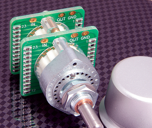
Figure 4. GoldPoint Step Attenuator
What do you get from a stepped attenuator for such a huge outlay? One is the ‘feel’ of the stepped level control, especially when coupled with a large, heavy knob. The second is precision relative tracking, as shown in Figure 5. As shown in the figure, as the inexpensive 50K Alpha pot is moved through its full range of resistance, the difference in resistance between left and right elements ranges from 0 to about 5K, with a marked peak around 18K. The tracking of the more expensive ALPHA potentiometer is much better, with a maximum difference of about 1.5K. The GoldPoint stepped attenuator, in comparison, showed no significant difference throughout the 50K ohm range.
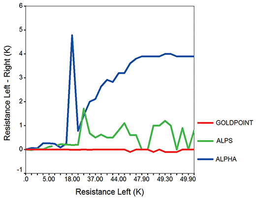
Figure 5. Relative Tracking, 50K Stereo Pots, And Step Attenuator
We could debate whether the variation in relative tracking for a given pot is detectable — most humans can detect a 3 db difference in sound level. We could also debate whether a simple balance control would provide a better, inexpensive solution for the channel tracking errors than a step attenuator. The choice is yours. However, at least consider the Alpha potentiometer as an alternative to a garden-variety potentiometer.
Layout
The layout of this project is straightforward. Simply follow the fully documented component layout layer on the PCB layout file. The file format is ExpressPCB, and the application for reading and editing the file is available for free download. If you elect to use an external power supply or a supply of your own design, then about 70% of the board design can be deleted.
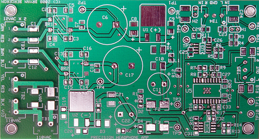
Figure 6. Printed Circuit Board, Component SIde
Figure 6 shows the component side of the board, and Figure 7 shows a close-up of the amplifier section of the populated board. Note the 20-pin TPA6120A2 near the upper third of Figure 7.
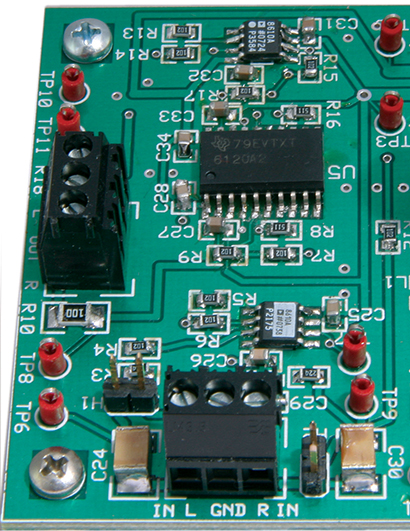
Figure 7. Close-up Of the Audio Amplifier Section Of the Populated PCB
Figure 8 shows the ground plane configuration and thermal vias for the TPA6120A2, taken from the ExpressPCB file. The TPA6120A2 is susceptible to oscillations, and removing the ground plane under key leads reduces inter-lead capacitance and tendency to oscillate. The ground plane is shown in green.
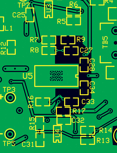
Figure 8. ExpressPCB Layout Showing Ground Plane Configuration And Thermal Vias For The TPA6120A2 (U5)
Construction
Working with the 20-pin surface-mount TPA6120A2 presents a modest challenge in that the belly of the IC must be soldered to thermal vias on the PCB. A hot air pencil is useful but not necessary for this step.
The cables, connectors, and other peripheral components should be wired directly to the relevant terminal blocks on the PCB. Keep the AC input lines separate from the audio input cables and output cables.
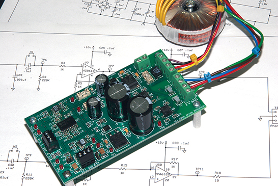
Figure 9. Amplifier With Standoffs And Toroidal Transformer, Ready For Mounting
Figure 9 shows the completed amplifier with toroidal transformer attached, ready for mounting, and Figure 10 shows a close-up of the instrument input jack and step attenuator wiring.
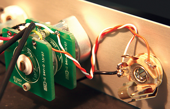
Figure 10. Wiring Of Step Attenuator And Instrument Input Jack
Testing
Carefully inspect your work — especially the solder joints of the three ICs. Use a low-current ohmmeter to check for obvious shorts. Use the test points to compare values from left and right channels.
Before you apply AC power, remove the two 1A fuses. Apply AC power to the transformer and verify that the power supply produces both +12 VDC and -12 VDC. Disconnect the AC power, replace the fuses, and reapply power. Apply a signal to the input jack and monitor the output with a pair of headphones. Because the amplifier circuit is symmetrical, voltage and signal levels should be symmetrical, as well. Therefore, if one side of your amplifier isn’t working, use voltage and signal measurements from the other side as a reference.
Packaging
Although any aluminum box of appropriate dimensions will do, I’m fond of the Hamond extruded aluminum boxes, and used the 8.6 x 6.3 x 2 inch HM905-ND with aluminum front and rear panels. For the front panel (see Figure 11), I splurged and designed a custom blue, white, and red one, using the software from Front Panel Express (www.frontpanelexpress.com).
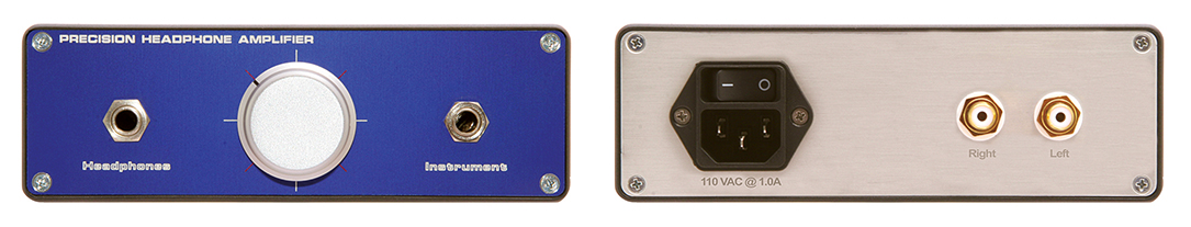
Figure 11. Front (Left) And Back (Right) Panel
For the rear, I used the panel that shipped with the Hamond box and ironed on lettering from a laser printout on Staples Photo Paper. Clean the panel with acetone before you iron on the lettering. Soak the paper in lukewarm water and peel it from the panel to expose the black lettering. Use your fingertips (not nails) to rub any paper remaining on the panel. Dry the panel and finish with Krylon satin clear coat.
Evaluation
Subjectively, the amplifier performs as well as my expensive commercial audio gear. It’s obviously much quieter than an LM386-based headphone amplifier that I built for another project. Music from my tube-type preamp, as well as guitar tones, are clean and crisp.
A proper comparison of this amplifier with other amplifiers involves objective measurements of factors such as THD+N. If you don’t happen to have a room full of audio test equipment, I suggest you use an inexpensive PC-based audio spectrum analyzer, such as TrueRTA. A low-resolution, fully-operational version of TrueRTA is available for free download from www.TrueAudio.com.
Figure 12 shows the noise level of the amplifier from 0–50 kHz.

Figure 12. Amplifier Noise Level, 0-50 kHz
As you can see from the figure, the noise level is constant across the measurement range at about -93 dB. As described in the TrueRTA documentation, the noise floor of your PC sound card limits the minimum noise that can be measured. Because of differences in sound cards and the impedance mismatch between the sound card input and amplifier output, I consider comparative results more meaningful than absolute measurement values. TrueRTA showed the noise floor for my 386-based amplifier was about 20 dB greater than for the precision amplifier.
Figure 13 shows the frequency response of the amplifier, again using TrueRTA.
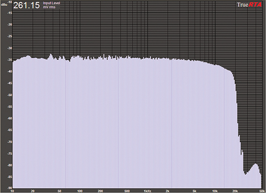
Figure 13. Frequency Response With Front End As Per Schematic
With the low-pass filter front end shown in the schematic with the 220K ohm resistor, the frequency response is flat from 0 to about 18 kHz. If your sound sources include signals above 18 kHz (and you can actually hear the signals), then consider modifying the input circuit. Removing the 220K resistor and using the 50K step attenuator results in a virtually flat frequency response from 0 to about 20 kHz, as shown in Figure 14. Note the curious frequency response between 20 kHz and 50 kHz associated with each input configuration.
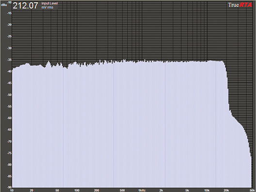
Figure 14. Frequecy Response With 50K Stepped Attenuator Input
From Here
The amplifier described here is meant to be modified to suit your needs. For example, I built two amplifiers, one configured as in the schematic, and mounted it permanently in my tube-type preamplifier.
I built a second amplifier with 50K stepped attenuator front end and mounted it in a Hamond case to use with my CD player, iPod, and electric guitar. I added an inexpensive line filter to reduce common mode noise. In addition, I replaced the 1K resistors at R6 and R14 with 2K resistors to provide 2x gain. As with most op-amps, the gain of the AD8610 is proportional to R6/R5 in the left channel and R14/R16 in the right channel. You can create a variable amplification option by replacing R6 and R14 with on-board eight-position switches and surface-mount resistors. Another option is to replace R6 and R14 with 10K pots. NV
Resources
Custom engraved front panels.
Front Panel Express www.frontpanelexpress.com
Step attenuators, audio connectors, capacitors, and cables.
DIYCable.com www.diycable.com
Step attenuators, knobs, and shaft couplers.
GoldPoint www.goldpt.com
Downloads
Precision Stereo Headphone Amplifier (Parts List, PCB, Schematic)