INTRODUCTION
All previous episodes of this series have dealt with security circuits that are designed for use in domestic, commercial, or industrial applications. By contrast, this concluding episode deals exclusively with fairly simple ‘add-on’ security circuits designed for use in automobiles fitted with normal 12V negative-ground electrical systems.
Modern automobiles virtually bristle with various ‘security’ devices and gadgets that are designed to enhance the vehicle’s safety, reliability, mechanical efficiency, and immunity to theft.
If you own a reasonably modern automobile, it is probably already so well-equipped with good security devices that you will not need to add any more. If, on the other hand, your vehicle is somewhat dated, you may be able to gain by fitting one or more of the simple circuits that are described in this article, or by using one or more of the various commercial ‘add-on’ vehicle security units that are widely available.
The circuits described here include simple engine immobilizers and anti-theft alarms, ice-hazard, low-fuel-level, and ‘lights-are-on’ alarms, a headlight time-delay switch, and a timed auto-turn-off rear-screen heater controller.
VEHICLE IMMOBILIZER CIRCUITS
Most immobilizers work by disabling the vehicle’s engine, thus minimizing a thief’s chances of starting or driving the automobile. The simplest and most effective way to immobilize a vehicle fitted with a normal petrol (gasoline) engine is to physically remove its ignition system’s rotor-arm.
This task (which was compulsory in the UK during WW2) only takes half a minute to perform, and is recommended whenever a vehicle is left parked in a public area for more than a few days, but is too inconvenient a practice for every-day use.
Instead, simple and convenient immobilizers can take the form of a secret switch (or remotely-controlled relay contacts) wired into some vital electrical part of the vehicle’s engine; Figures 1 to 4 show some basic circuits of this type.
Figures 1 and 2 show how immobilizers can be wired into the engine’s ignition system. In Figure 1(a), switch S1 is wired across the engine’s contact-breaker (CB) points; when S1 is open, the ignition operates normally, but when it is closed, the CB points are shorted out and the engine is unable to operate. This simple circuit gives excellent protection, particularly if the wiring is carefully concealed at the CB end, but S1 must be able to handle the coil’s high operating current when it is closed, and be able to withstand the CB point’s typical 600V peak-to-peak ‘ringing’ voltages when the engine is operating normally.
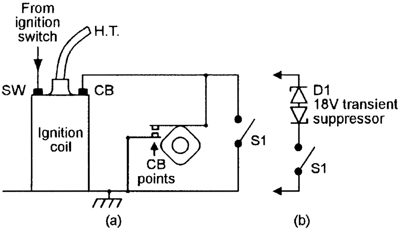
FIGURE 1. Contact-breaker immobilizer, operates when switch is closed.
The improved immobilizer circuit of Figure 1(b) does not suffer from the above snags. Here, an inexpensive and easily available 18V transient suppressor diode (D1) — which acts like a pair of back-to-back zeners — is wired in series with S1. This device passes no current until its applied voltage exceeds 18V, and acts like a near-short to voltages greater than 18V. Thus, in this circuit, S1 passes zero DC current when it is closed, but kills the ignition systems vital ‘ringing’ voltages when an attempt is made to start the engine. This circuit gives superb anti-theft protection.
In Figure 2, the immobilizer switch is wired in series with the vehicle’s ignition switch, so that the engine operates only when the switch is closed. The protection offered by this widely-used type of circuit is not quite as good as that of Figure 1, since a moderately skilled thief can easily bypass the immobilizer and ignition switches by simply hooking a wire from the battery to the SW terminal of the ignition coil.
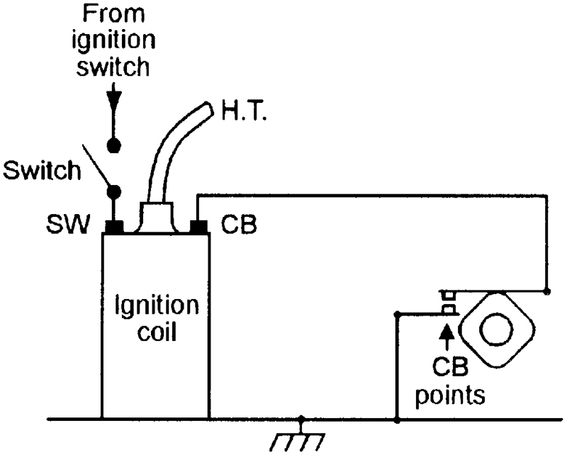
FIGURE 2. Ignition immobilizer, operates when switch is open.
Figure 3 shows how a heavy-duty immobilizer switch can be wired into the vehicle’s electric starter system, so that the starter only operates if this switch is closed. This system gives better protection than that of Figure 2, but is not as good as Figure 1 because the starter solenoid can be operated manually on many old vehicles, and also because the starter and immobilizer switches can be bypassed by a single length of wire.
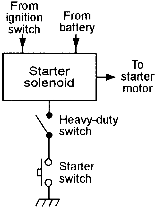
FIGURE 3. Starter-motor immobilizer, operates when switch is open.
Finally, Figure 4 shows how an immobilizer switch can be wired in series with the electric fuel pump on suitable vehicles, so that the pump only operates when this switch is closed. Note that this system lets a thief start the engine and drive for a short distance on the carburetor’s residual fuel, which is quickly used up.
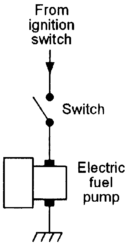
FIGURE 4. Fuel-pump immobilizer, operates when switch is open.
A weakness of the Figure 1 to 4 circuits is that they must all be turned on and off manually, and thus only give protection if the owner remembers to turn them on. By contrast, Figure 5 shows an immobilizer that turns on automatically when an attempt is made to start the engine, but can be turned off by briefly operating a hidden push-button switch. A small ‘reminder’ LED turns on when the engine is disabled by the immobilizer. This circuit thus gives a high level of protection, since it does not depend on the memory of its owner, and operates as follows.
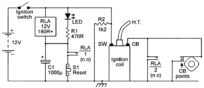
FIGURE 5. Self-activating immobilizer circuit.
The coil of 12V relay RLA is shunted by series-connected R1 and an LED, which illuminates when RLA is on, and this combination is wired in series with 1000µF capacitor C1, which is shunted by series-connected n.o. relay contacts RLA/1 and n.c. push-button switch S1. This RLA-C1 combination is wired between the ignition coil’s SW terminal and ground, and the relay’s RLA/2 n.o. contacts are wired across the vehicle’s CB points (using a Figure 1b connection).
Normally, C1 is fully discharged; consequently, when the ignition switch is first closed a surge of current flows through RLA coil via C1, and the relay turns on and the LED illuminates. As the relay goes on, contacts RLA/1 close and lock the relay on via S1, and contacts RLA/2 close and short out the vehicle’s CB points, thus immobilizing the engine. The relay stays on until S1 is briefly opened, at which point the relay unlatches and C1 charges up rapidly via the relay coil, and the relay and LED then turn off. As the relay turns off, it removes the short from the vehicle’s CB points, and the engine is able to operate in the normal way.
ANTI-THEFT ALARM CIRCUITS
Vehicle anti-theft alarms come in a variety of basic types, and the most reliable of these are the types that are switched on/off externally (rather than internally) and are activated via simple door-controlled microswitches or via a battery-voltage sensing circuit.
In modern vehicles, the external on/off control function is usually obtained via an IR remote-control system, but on older vehicles, it can be obtained cheaply and simply via a prominent key-switch (or a concealed toggle switch) fitted to the outside of the vehicle. Figures 6 to 8 show practical alarm systems of these types that are designed for use in older vehicles; each of these circuits can also act as an immobilizer and, if required, operates the vehicle’s horn and lights and immobilizes the engine under the ‘alarm’ condition.
In the Figure 6 and 7 circuits, microswitches that are built into the vehicle are used (when the alarm system is enabled) to trip a pair of self-latching relays when any of the car doors, hood, or trunk are opened; these relays immobilize the engine and operate the horn and headlights either directly or via additional timing circuitry.
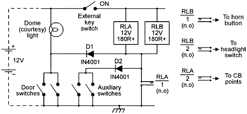
FIGURE 6. Basic microswitch-activated anti-theft alarm/immobilizer.
Two suitable front-door microswitches are built into most vehicles as standard fittings and are used to operate the courtesy or dome lights; additional dome-light-operating microswitches — which are readily available from specialist ‘vehicle security’ retailers — can easily be fitted to the rear doors. Similar microswitches can be used as ‘auxiliary’ switches to protect the hood and trunk (bonnet and boot).
The operation of the Figure 6 circuit is very simple. The alarm is enabled by closing the external key switch. When the key switch is closed, current flows through both relays via D1 if any of the door switches close, or flows through them via D2 if any of the auxiliary switches close. In either case, both relays turn on.
As RLA goes on, contacts RLA/1 close and lock both relays on, and contacts RLA/2 close and short out the vehicle’s CB points (using a Figure 1b connection), thus immobilizing the vehicle. Simultaneously, contacts RLB/1 close and switch on the car horn (or a siren unit), giving an audible indication of the intrusion, and contacts RLB/2 close and switch on the headlights (or activate a headlight flasher unit), giving a visual identification of the violated vehicle. The horn and light (etc.) remain on until the key-switch is opened.
Obvious weaknesses of the simple Figure 6 circuit are that, if it is activated and is not switched off manually within a reasonable space of time (typically 15 minutes), it will probably break local noise-control regulations, will probably damage the horn, and will eventually flatten the vehicle’s battery. Figure 7 shows a way of modifying the Figure 6 circuit so that the horn and lights turn off automatically after about four minutes, but the immobilizer stays active until turned off via the key switch, thus eliminating all of the above problems.
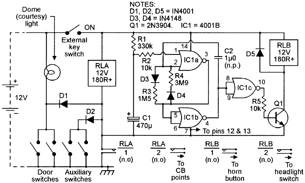
FIGURE 7. Improved anti-theft alarm/immobilizer has pulsed and time-controlled outputs.
In Figure 7, RLA turns on and self-latches in the same way as in the Figure 6 circuit, but as contacts RLA/1 close, they connect the full battery voltage across the RLB-driving timer-gated asymmetrical pulse generator formed from a 4001B CMOS IC and Q1. This generator is activated for about four minutes, via R1-C1, whenever RLA is turned on by a ‘break-in’ detector, and repeatedly pulses RLB (and thus the vehicle’s lights and horn) on and off, for unequal periods, for the duration of this four-minute period.
During this ‘pulsing’ period, the ‘off’ time of RLB is controlled by C2-D3-R3 and approximates 1.5 seconds, and the ‘on’ time is controlled by C2-D4-R4 and approximates four seconds, and the vehicle’s horn thus generates a distinctive and easily recognized warning signal. Note that C2 is a non-polarized (n.p.) capacitor.
Finally, to complete this look at anti-theft alarm circuits, Figure 8 shows the practical circuit of a simple voltage-sensing type of alarm unit that can be used in place of the basic RLA-driving network used in the Figure 6 and 7 designs. Circuit operation relies on the fact that (when the vehicle’s engine is not operating) a small but sharp drop occurs in the vehicle’s battery voltage whenever a courtesy light is automatically turned on by the opening of a front door, or when the ignition is switched on. This sudden drop in voltage is detected and made to operate RLA. The system has the advantage that its ‘alarm’ signals are derived directly from the vehicle’s battery, rather than via various microswitches, but it is not quite as reliable as a conventional microswitch-activated alarm system.

FIGURE 8. Basic voltage-sensing alarm circuit.
The operation of the Figure 8 circuit — which is connected across the vehicle’s battery via S1 — is fairly simple. Here, potential divider R1-R2-R3 is wired across the circuit’s supply lines, and the output of this divider is fed, via RV1-R4, to the inverting (pin 2) input terminal of the 741 op-amp, which is wired in the open-loop mode, but is taken to the non-inverting (pin 3) input via a simple (R5-C1-R6) time-delay ‘memory’ network. A small offset voltage can be applied between the two input terminals via RV1.
Suppose then that the RV1 offset control is adjusted so that the pin 2 voltage is fractionally higher than that of pin 3 under normal ‘steady voltage’ conditions and, that under this condition, the output of the op-amp is driven to negative saturation. Now if a small but abrupt fall occurs in the supply voltage, this fall is transferred immediately to pin 2 of the op-amp, but does not immediately reach pin 3 because of the time-delay or memory action of C1.
Consequently, pin 2 briefly goes negative relative to pin 3, and as it does so, the output of the op-amp is driven briefly to positive saturation, thus giving a positive output pulse. This pulse is used to charge C2 via D1, and C2 drives Q1-Q2 and relay RLA on via R7. As RLA goes on, contacts RLA/1 close and self-latch the relay, and contacts RLA/2 close and immobilize the vehicle via its CB points.
Note that this circuit responds only to sudden drops in voltage, and is not influenced by stable absolute values of battery voltage.
The Figure 8 circuit can be used directly in place of the RLA network in the Figure 6 or 7 circuits. When installing the circuit in a vehicle, RV1 must be carefully adjusted so that the alarm turns on reliably when the courtesy (dome) light goes on, without being excessively sensitive to the small shifts that occur in the battery voltage due to its chemical action.
To find the correct setting of RV1, temporarily disable self-latching contacts RLA/1, and temporarily replace the courtesy lamp with one having roughly half its normal current rating.
Now adjust RV1 just past the point where RLA fails to activate when the lamp goes on, and then turn RV1 back a fraction, so that RLA is just activated by the courtesy light. Now refit the original courtesy light, and recheck the action. If reliable action is obtained, re-enable the RLA/1 contacts.
INSTALLING ANTI-THEFT ALARMS
The anti-theft alarms described in the last section are all designed to be turned on and off via an externally mounted switch, which may take the form of a carefully hidden toggle switch or a prominently mounted key-switch. In either case, the switch must be mounted so that neither it or its wiring is vulnerable to damage by weather, dirt, or potential car thieves.
Once the alarm’s external on/off switch has been fitted, the next installation job is to fit suitable microswitches to activate the system. Two suitable switches are already fitted to most vehicles, and are used to operate the dome or courtesy light. Additional switches must be fitted to the rear doors, and must also be fitted to the trunk and hood if full anti-theft protection is to be obtained.
Note that if your vehicle is fitted with a voltage-sensing type of alarm system, these microswitches must be used to switch a normal filament lamp; the higher the load current used, the more reliable will be the operation of the alarm circuit; the microswitches can all be wired in parallel and used to drive a single load. When installation is complete, give your system a complete functional check, taking care not to annoy your neighbors in the process.
ICE-HAZARD ALARMS
Ice-hazard alarms activate when the vehicle’s ignition is turned on and the air temperature several inches above the road surface is at or below the 0°C freezing point of water. The alarms thus indicate a risk of meeting ice under actual driving conditions. Two useful ice-hazard alarms are shown in this section, and can easily be fitted to most automobiles. Both units use a low-cost n.t.c. thermistor — mounted outside of the vehicle, near its front and several inches above the road surface — as a thermal sensor that gives a good indication of the actual road temperature.
The first circuit, shown in Figure 9, connects to the vehicle’s 12V supply via its ignition switch, and turns-on relay RLA under the ‘ice-hazard’ condition; the RLA/1 contacts can be used to activate any desired type of external alarm device. In this circuit, the 3140 op-amp is used as a voltage comparator, in which a presettable reference voltage is applied to its pin 3 input via RV1, a temperature-sensitive variable voltage is applied to pin 2 from the R1-TH1 potential divider, and the action is such that the pin 6 output of the op-amp switches low and activates Q1 and RLA if the variable voltage exceeds the reference voltage.
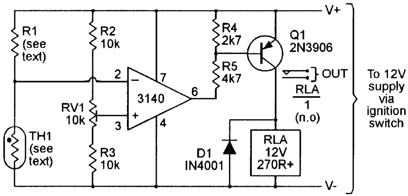
FIGURE 9. Relay-output ice-hazard alarm.
In practice, the output voltage of the R1-TH1 divider rises as the TH1 temperature falls, and — if the circuit is correctly set up — trips relay RLA at a TH1 temperature of precisely 0°C.
This circuit’s thermistor can be any n.t.c. disc or bead type that has a resistance in the range 1K5 to 5K0 at 25°C (the normally-specified ‘nominal resistance value’ temperature of most thermistors). Typically, the TH1 resistance at 0°C is about treble the 25°C value and, in this circuit, the R1 value should roughly equal TH1’s ‘0°C’ value; thus, if TH1 has a nominal 25°C value of 1K5, R1 needs a value of about 4K5. Note, however, that the precise R1 value is not critical, since balance-control RV1 can compensate for errors in the range -50% to +100% in the R1 value. The actual methods of mounting TH1 and setting RV1 are described later in this section.
In most practical ice-hazard alarm applications, the hazard condition may continue intermittently during several hours of driving, and it is thus best to use a flashing-LED type of ‘hazard alarm’ indicator, rather than a continuously-active audible-warning type. Figure 10 shows the Figure 9 circuit modified to give a flashing-LED alarm output directly, rather than via a relay. In this case, Q1 is wired as an emitter-follower, and drives on D1 — a low-cost flashing LED device — when the op-amp output switches low. Note that R4-ZD1 and Q1’s base-emitter volt-drop limit D1’s maximum applied voltage to a safe value of 9.4 volts.
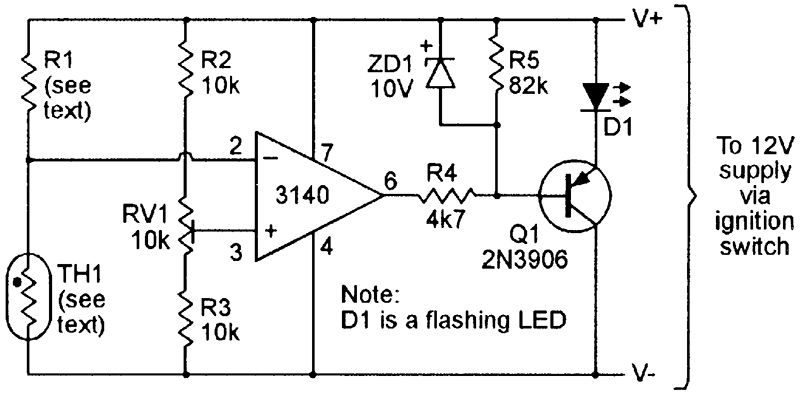
FIGURE 10. Ice-hazard alarm with flashing LED output.
When building either of these ice-hazard alarms, note that thermistor TH1 must be mounted in a small ‘head’ that is fixed to the lower front of the vehicle and connected to the main alarm-unit via twin flex. To make the head, solder the thermistor to a small tag-board and solder its leads to the twin flex. Coat the whole assembly with waterproof varnish, so that moisture will not affect its apparent resistance, then mount it in a small plastic or metal box and fix it to the lower front of the vehicle. Before fixing the head in place, however, calibrate the alarm system as follows.
Immerse the head in a small container filled with a water and ice mixture. Use a thermometer to measure the temperature of the mixture, and add ice until a steady reading of 0°C is obtained. Now adjust RV1 so that the alarm (RLA or the flashing LED) just turns on; raise the temperature slightly, and check that the alarm turns off again. If satisfactory, the head and the alarm system can now be fixed to the vehicle.
A LOW FUEL LEVEL ALARM
One of the most annoying things that can happen to a car driver is to run out of fuel after having failed to notice the advance-warnings shown on the vehicle’s fuel gauge. This event can easily be avoided by fitting the vehicle with a simple circuit that monitors the fuel gauge and activates a flashing-LED alarm under potential ‘danger’ conditions. A circuit of this type is shown in Figure 12, it uses the same flashing-LED type of output stage as the Figure 10 circuit, but can be made to give a relay output by replacing this with the type of output stage used in the Figure 9 circuit.
Most reasonably-modern vehicles are fitted with an analog fuel-level gauge circuit that takes the basic form shown in Figure 11.

FIGURE 11. Basic circuit of a typical fuel level gauge.
Here, the gauge is actually a hot-wire (bimetal) current meter that is wired in series with a ‘sender’ unit that is mounted in the fuel tank and consists of a float-driven rheostat that presents a high resistance (and a low current meter reading) when the tank is empty, and a low resistance (and a high current meter reading) when the tank is full. Note that the output voltage of the sender rises as the fuel level falls, and a low fuel level alarm can thus take the basic form of a simple over-voltage alarm. A suitable ‘flashing-LED’ alarm circuit is shown in Figure 12.
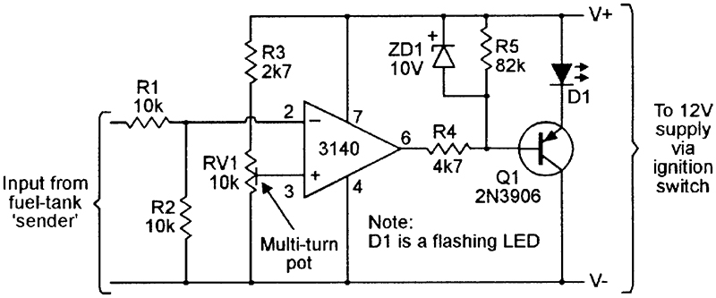
FIGURE 12. Low fuel level alarm.
Before starting to build the Figure 12 circuit, check that you can gain easy access to the tank-mounted sender unit or the rear of the fuel gauge, and that the sender’s output voltage varies in the way described above.
In the Figure 12 circuit, the 3140 op-amp is wired as a voltage comparator, with a pre-set fraction of the supply voltage applied to pin 3 via multiturn pot RV1, and with half of the sender’s output voltage applied to pin 2 via the R1-R2 potential divider. The op-amp’s output goes low and activates the flashing LED (via Q1) when the pin 2 voltage rises above the pre-set pin 3 value. To set up the circuit, wait until the fuel falls to the required ‘danger’ level, then connect the unit to the vehicle’s supply via the ignition switch and trim RV1 so that the flashing LED just turns on. Check that the flashing LED turns off when the fuel level is increased by a modest amount.
LIGHTS-ARE-ON ALARMS
Most modern automobiles are fitted — as standard equipment — with a lights-are-on reminder unit that emits a low-power audible alarm signal that warns the driver — as he/she opens the driver’s door — if the car lights have been left on. ‘Lights-are-on’ alarm units of this basic type are easy to build and are fairly easy to add to most older types of vehicle, and come in two basic types. Type-1 is for use in very old vehicles that are not fitted with a courtesy light that is switched automatically via a conventional door-activated microswitch, and Type-2 is for use in vehicles that are fitted with such a courtesy light system.
Figure 13 illustrates the basic operating principles of a Type-1 lights-are-on alarm circuit. Here, the actual alarm consists of a low-power 15-second buzzer or siren unit that has its supply lines wired in series with diode D1 so that current can only flow through the unit (and thus activate the buzzer/siren) when point-X is many-volts positive to point-Y. And, in the diagram, this situation only occurs when ‘lights’ switch S1 is in the ON (Side or Head) position and ‘ignition’ switch S2 is turned OFF. Thus, if the lights are left on, the alarm unit sounds-off as soon as the ignition is switched off, but mutes automatically after 15 seconds.
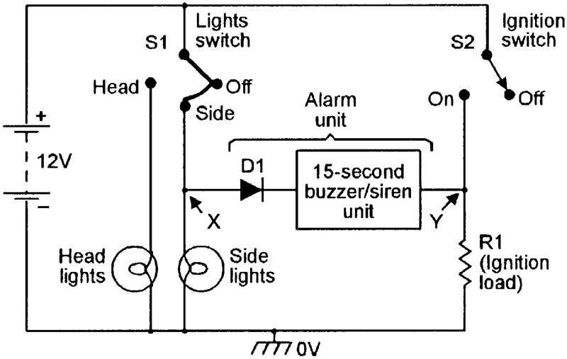
FIGURE 13. Basic Type-1 ‘lights-are-on’ alarm circuit.
Figure 14 shows a simple but practical version of a Type-1 ‘lights-are-on’ alarm unit. Here, Q1-Q2 are wired as a modified complementary astable multivibrator that has its power supplied via D1 and uses a 64R low-power speaker as the collector load of Q2, which is a 2N3704 type and has a peak collector current rating of 800mA.
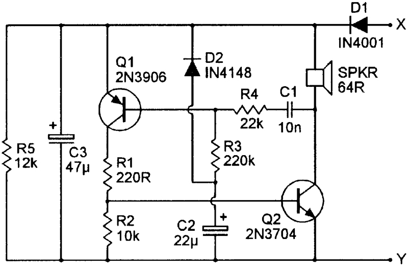
FIGURE 14. Practical Type-1 ‘lights-are-on’ alarm unit.
The astable’s action is such that it generates a loud and fairly high alarm tone when power is initially applied, but the volume and frequency then decay steadily down to zero over a period of about 15 seconds. The decay time is controlled by R3-C2, and the initial frequency is controlled by R3-R4 and C1. To use the unit, simply connect its ‘X’ and ‘Y’ points in the way shown in Figure 13.
Figure 15 illustrates the basic operating principles of the Type-2 lights-are-on alarm. It is similar to the Type-1 system, except that the alarm unit is wired between ‘lights’ switch S1 and dome-light-activating door-switch S2, so that the alarm only sounds if the lights are on when the driver’s door is open.
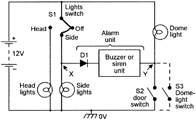
FIGURE 15. Basic Type-2 ‘lights-are-on’ alarm circuit.
The above Type-2 system is used on most modern vehicles, in which the dome light uses separate circuits for its ‘courtesy’ and ‘reading’ lights. A snag with most older vehicles is that they use a single light-bulb to perform both of these functions, with the ‘reading’ switch wired in parallel with S2, as shown by S3 in Figure 15 and, as a consequence, the alarm can be activated by either of these switches.
The easiest way around this snag is to use an auto-turn-off alarm unit that, like the Type-1 unit, only sounds for a dozen or so seconds when activated. The alarm unit can thus take the simple ‘monotone’ form shown in Figure 14, or can take the more attractive ‘warble-tone’ form shown in the Figure 16 circuit.
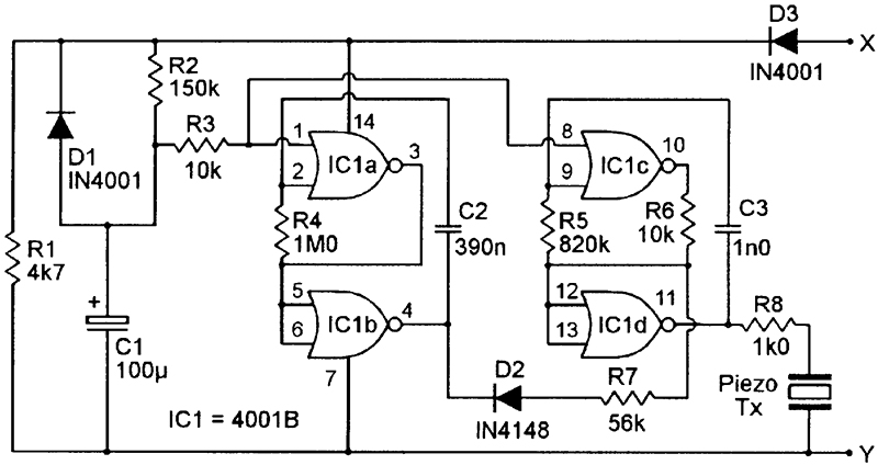
FIGURE 16. Practical warble-tone Type-2 ‘lights-are-on’ alarm unit.
The Figure 16 circuit is based on warble-tone circuits shown in Part 3 of this series. In brief, however, IC1a-IC1b and R4-C2 are wired as a gated l.f. (low-frequency) astable and IC1c-IC1d and R5-C3 form a gated h.f. (high-frequency) astable. Both astables are gated via the R2-C1 time-constant network, and are on when C1’s output is below half-supply volts and off when C1’s output is above half-supply volts.
When the astables are gated on, the l.f. astable frequency-modulates the h.f. astable (via D2-R7-R6), which has its output fed to piezo output transducer Tx via R8.
When power is connected to the Figure 16 circuit, C1 is initially fully discharged, so both astables are gated on and generate a warble-tone sound in the piezo Tx, but C1 then charges up via R2 and after a delay of about 15 seconds (determined by R2-C1) gates both astables off, silencing the piezo Tx.
When the unit’s power connections are removed, C1 rapidly (in a second or so) discharges via D1-R1, and the unit is then ready to repeat its operating sequence when power is connected again.
A HEADLIGHT TIME-DELAY SWITCH
Headlight time-delay switches are simple add-on units that, when activated by a push switch, turn a car’s headlights on for just a few minutes, during which the owner can leave and lock the vehicle, walk along a drive or pathway that is well lit by the headlights, and then enter the security of a safe building before the lights automatically turn off again. Figure 17 shows a practical transistor version of such a circuit.
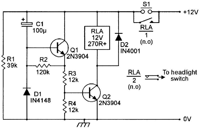
FIGURE 17. A headlight time-delay switch circuit.
In Figure 17, Q1 is an emitter follower that uses R3-R4 as its emitter load, but has ‘bootstrapped’ resistor R2 wired between its base and emitter, so that R2’s impedance — as seen from Q1’s base — is many times greater than its DC resistance value. C1 and Q1’s input impedance (which equals the parallel values of R2’s impedance and Q1’s base impedance) form a C-R time-constant network.
The action of Q1 and this network is such that, when power is first connected to the circuit by briefly closing push-button switch S1, C1 is fully discharged and thus pulls Q1’s base and emitter up to almost the full positive supply voltage, thus driving relay-activating common-emitter amplifier Q2 on via R3; as relay RLA turns on, contacts RLA/1 close and lock the supply on, and contacts RLA/2 close and turn the vehicle’s headlights on.
As soon as power is connected to the circuit, C1 starts to charge up via the very high parallel impedances of R2 and Q2’s base, and Q2’s emitter voltage (and the current fed into Q2’s base via R3) starts to decay exponentially until, after a delay of about two minutes, these values fall so low that RLA turns off, thus breaking the supply connection as RLA/1 opens and turning off the headlights as RLA/2 opens. C1 discharges rapidly via R1-D1 when the circuit’s power connection is broken.
A REAR-SCREEN HEATER TIMER
Automobile rear-screen heaters draw typical operating currents of about 15 amps and thus place a heavy strain on the vehicle’s electrical generating system. If the heater is inadvertently left on for long periods, this strain can greatly reduce the generator’s reliability and working life.
Consequently, most modern automobiles are fitted with push-button operated rear-screen heater controllers that turn the heater off automatically after an operating period of about 16 minutes. Reliability-enhancing units of this basic type can easily be added to older vehicles and, to conclude this series, Figure 18 shows a practical add-on circuit of this type.
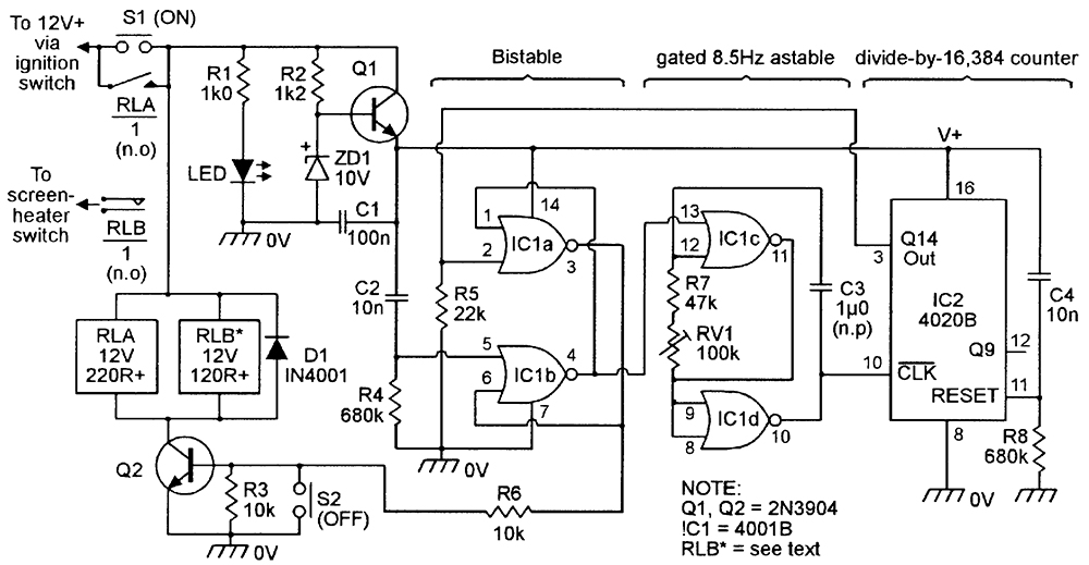
FIGURE 18. A rear-screen heater timer circuit.
The Figure 18 circuit incorporates a simple voltage regulator built around transistor Q1, a stable 16-minute timer built around IC1 and IC2, and relays RLA (which controls the circuit’s semi-latching function) and RLB (which controls the rear-screen heater’s power feed), and derives its power feed via the vehicle’s ignition switch. The complete circuit operates as follows.
The Figure 18 circuit is turned on by briefly closing push button switch S1. As S1 closes, the LED illuminates, a stable 9.4V supply is applied to the IC1-IC2 timer circuit via Q1, and ‘reset’ pulses are fed to the IC1a-IC1b bistable (via C2-R4) and the IC2 counter (via C4-R8).
As the bistable resets, its pin 3 output flips high and turns on RLA and RLB via Q2; as the relays turn on, the RLA/1 contacts close, shunting S1 and locking-on the circuits supply connection, and RLB/1 contacts close and connect power to the rear-screen heater.
Simultaneously, as the IC1a-IC1b bistable resets, its pin 4 output flips low and turns on the IC1c-IC1d gated astable, which starts feeding clock pulses into pin 10 of the IC2 counter at an 8.5Hz rate.
Sixteen minutes later, in the arrival of the astable’s 8192nd clock pulse, the pin 3 output of IC2 flips high and changes the state of the IC1a-IC1b bistable, which simultaneously gates off the astable and removes Q2’s base drive, thus turning off both relays; as RLA turns off, it removes the timer’s supply connection, and as RLB turns off, it removes power from the rear-screen heater.
Thus, when the vehicle’s ignition is turned on, the Figure 18 circuit connects power to the rear-screen heater as soon as S1 is closed, but removes it again automatically after 16 minutes. If desired, the timing period can be ended prematurely by briefly closing S2, thus turning off both relays.
The circuit’s timing period can, if you wish, be set to exactly 16 minutes by temporarily connecting an LED and 2K7 series resistor between pins 12 and 8 (0V) of IC2 and trimming RV1 so that the LED operates with precise 30-second on and off periods.
When building this circuit, note that RLA’s contacts have to pass maximum currents of less than 200mA, and RLA can thus be almost any general-purpose relay, but that RLB’s contacts have to pass the full operating current of the rear-screen heater (typically 15A), and RLB must thus be a dedicated heavy-duty ‘automobile’ relay. NV