
INTRODUCTION
In our opening episode of this new series, we started off by looking at electronic security system basic principles, and went on to explain that all such systems contain a number of major elements, including a sensing unit, one or more data links, and some kind of alarm response unit. We then went on to look at various types of electromechanical and electrical sensor devices.
This episode continues this theme by looking at various types of electronic sensor devices, various types of data links, and various types of alarm response units.
Next time, we'll look at practical contact-activated security systems and alarm circuits.
ELECTRONIC SENSOR DEVICES
An ‘electronic’ sensor may take the form of a single semiconductor component such as a photodiode or phototransistor, or may be a combination of electrical and/or electronic components that together perform a particular sensing function; examples of the latter type are electronic key-pad locks and light-beam alarms. The most important of such devices are described in this section.
PHOTODIODES
When p-n silicon junctions are reverse-biased, their leakage currents and impedances are inherently photo-sensitive; they act as very high impedances under dark conditions and as low impedances under bright ones.
Normal diodes have their junctions shrouded in opaque material to inhibit this effect, but photodiodes are made to exploit it and use a translucent casing material; some photodiodes are made to respond to visible light, and some to infrared (IR) light. Figure 1(a) shows the standard symbol of a photodiode.
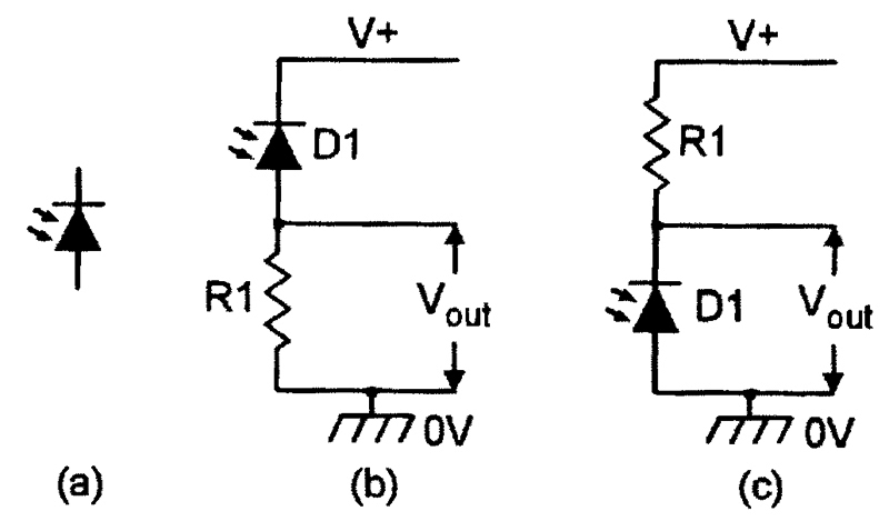
FIGURE 1. Photodiode symbol (a) and alternative ways ((b) and (c)) of using a photodiode.
In use, the photodiode is simply reverse-biased and the output voltage is taken from across a series resistor, which may be connected between the diode and ground as shown in Figure 1(b), or between the diode and the positive supply line, as in Figure 1(c).
PHOTOTRANSISTORS
Ordinary silicon transistors are made from an npn or pnp sandwich, and thus inherently contain a pair of photo-sensitive junctions. Some types are available in phototransistor form, and use the standard symbol shown in Figure 2(a). Figures 2(b) to 2(d) show three basic ways of using a phototransistor. In each case, the base-collector junction is effectively reverse-biased and thus acts as a photodiode. In Figure 2(b), the base is grounded, and the transistor acts as a simple photodiode.
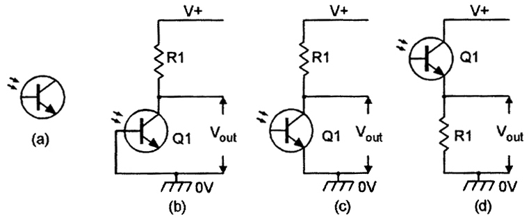
FIGURE 2. Phototransistor symbol (a) and alternative ways ((b) to (d)) of using a phototransistor.
In Figures 2(c) and 2(d), the base terminal is open-circuit and the photo-generated currents effectively feed directly into the base and, by normal transistor action, generate a greatly amplified collector-to-emitter current that produces an output voltage across series resistor R1.
The sensitivity of a phototransistor is typically 100 times greater than that of a photodiode, but its useful maximum operating frequency (a few hundred KHz) is proportionally lower than that of a photodiode (10s of MHz).
Some phototransistors are made in very-high-gain Darlington form.
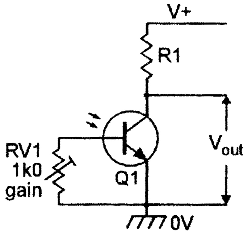
FIGURE 3. Variable-sensitivity phototransistor circuit.
A phototransistor’s sensitivity (and operating speed) can be made variable by wiring a variable resistor between its base and emitter, as shown in Figure 3. With RV1 open circuit, phototransistor operation is obtained; with RV1 short circuit, photodiode operation occurs.
OPTOCOUPLERS
An optocoupler is a device housing an LED (usually an IR type) and a matching phototransistor; the two devices are optocoupled, but are electrically isolated from each other and — in a normal type of optocoupler — are mounted in a light-excluding housing.
Figure 4 shows a basic optocoupler ‘usage’ circuit. The LED is used as the input side of the circuit, and the phototransistor as the output. Normally, SW1 is open and the LED and Q1 are thus off. When S1 is closed, a current flows through the LED via R1, and Q1 is turned on optically and generates an output voltage across R2.
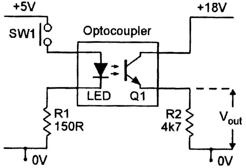
FIGURE 4. Basic optocoupler circuit.
The output circuit is thus controlled by the input one, but the two circuits are fully isolated electrically (‘isolation’ is the major feature of this type of optocoupler, which can be used to couple either digital or analog signals).
The Figure 4 device is a standard type of optocoupler. There are, however, two special types of optocouplers that are of particular value in security electronics applications, and these are shown in Figures 5 and 6.
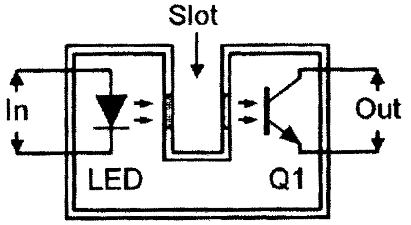
FIGURE 5. Slotted optocoupler device.
The Figure 5 ‘slotted’ device has a slot molded into the package between the LED light source and the Q1 light sensor. Light can normally pass from the LED to Q1 via a pair of windows in the slot walls, but can be blocked by placing an opaque object in the slot. The slotted optocoupler can thus be used in a variety of ‘presence detecting’ applications, such as limit switching and dark-liquid level detection.
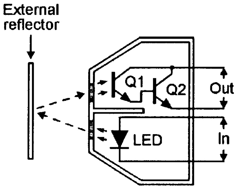
FIGURE 6. Reflective optocoupler.
The Figure 6 ‘reflective’ optocoupler has the LED and the Q1-Q2 Darlington light sensor optically screened from each other within the package, but arranged so that they both point outwards — via windows — towards an external point.
The construction is such that an optocoupled link can be set up by a reflective object (such as metallic paint or tape) placed a short distance outside the package, in line with the LED and Q1.
The reflective optocoupler can thus be used in applications such as tape-position detection, engine- or motor-shaft RPM measurement, or marked-object theft (illegal movement) detection, etc.
LIGHT-BEAM UNITS
Most modern ‘light-beam’ units work on the basic principle illustrated in Figure 7, in which a focused invisible beam of pulsed infrared light is generated by a transmitter unit, and is detected at a remote point by a matching lense and receiver/detector unit.

FIGURE 7. Basic infrared light-beam alarm system.
Normally, the unit is configured so that the receiver generates an alarm output if the IR beam is interrupted.
Such units have useful operating ranges of up to 30 meters and are often used in industry in automatic batch counting and safety-switch operating applications, and in commercial and domestic applications as intruder-detecting security alarms.
Simple single-beam alarms of the basic Figure 7 type have fairly low values of reliability, since they can easily be triggered by insects settling on one or other of the unit’s lenses, but dual-beam types of alarm — in which both the transmitter and the receiver use two lenses placed a few inches apart — have high values of reliability.
PYROELECTRIC IR DETECTORS
Some special crystals and ceramics generate electric charges when subjected to thermal variations or uneven heating; this is known as a pyroelectric effect. Pyroelectric infrared detectors incorporate one or two elements of this type, plus a simple filtering lense and a field-effect transistor (FET), configured in the basic way shown in Figure 8(a).
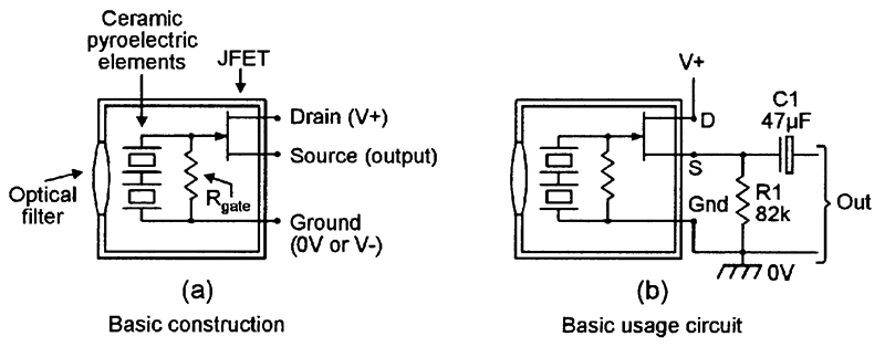
FIGURE 8. Basic construction (a) and usage circuit (b) of a pyroelectric infrared detector.
The basic action of the device is such that — if a human body moves within the visual field of its pyro-electric elements — part of the radiated infrared energy of that body falls on the surface of the elements and is converted into a minute variation in surface temperate and a corresponding variation in the element’s output voltage.
When the unit is wired as shown in the Figure 8(b) basic usage circuit, this movement-inspired voltage variation is made externally available via the buffering JFET and capacitor C1 and can, when suitably amplified and filtered, be used to activate an alarm when a human body movement is detected.
Note that pyroelectric IR detector circuits of the basic type described above have, because of the small size of the detector’s light-gathering lense, maximum useful detection ranges of just over one meter, but that this range can be extended to more than 10 meters with the aid of a relatively large external light-gathering/focusing lense of the type used in modern passive infrared (PIR) movement detector systems (see last month’s Figure 4 and its associated text).
PIEZOELECTRIC TRANSDUCERS
A piezoelectric transducer is an electro-constrictive device that converts a varying electrical signal into a sympathetic set of fine mechanical variations, or vice versa.
Devices of this type include piezo sounders, ‘crystal’ earphones and microphones, ordinary quartz crystals, and ultrasonic transducers.
Most devices of the latter type are sharply tuned low-power units designed to peak at about 40KHz, and are supplied in matching pairs, with one optimized for use as a signal transmitter and the other as a signal receiver.
They are useful in many remote control and distance-measurement applications, and in ‘doppler effect’ intruder alarm systems of the basic type shown in Figure 9.
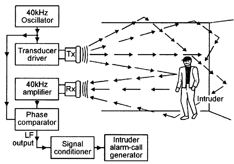
FIGURE 9. Block diagram of an ultrasonic (40KHz) doppler-effect intruder alarm system.
The Figure 9 intruder alarm system consists of three main elements.
The first is a transmitter (Tx) that floods the room with 40KHz ultrasonic signals, which bounce back and forth around the room.
The second is a receiver (Rx) that picks up and amplifies the reflected signals and passes them to a phase comparator, where they are compared with the original 40KHz signal.
If nothing is moving in the room, the Tx and Rx signal frequencies will be the same, but if an object (an intruder) is moving in the room, the Rx signal is doppler-shifted by an amount proportional to the rate of object movement (by about 66Hz at 10 inches/sec).
The lF output of the comparator is passed on to the third system element, the alarm activator, which is a signal conditioner that rejects spurious and out-of-limits signals, etc., and activates the alarm-call generator only if an intruder is reckoned to be genuinely present.
In practice, many systems of this basic type have poor reliability when set to high-sensitivity levels, since they can easily be false-triggered by draughts, central-heating air currents, and curtain movements, etc.
Low-sensitivity versions of the system are often used to protect small areas, such as the interiors of automobiles, however, and usually have high values of reliability.
ELECTRET MICROPHONES
Electret microphones are modern highly-efficient ‘capacitor’ microphones, and use the basic form of construction shown in Figure 10.

FIGURE 10. Basic elements of a modern electret microphone.
Here, a lightweight metallized diaphragm forms one plate of a capacitor, and the other plate is fixed and is metallized on to the back of a slab of insulating material known as electret; the capacitance value thus varies in sympathy with the applied acoustic (sound) signal.
The electret material holds a fixed electrostatic charge that is built in during manufacture and can be held for an estimated 100-plus years; this charge is applied between the two plates. The voltage across the capacitor equals this charge divided by the capacitance value and — since this varies in sympathy with the applied acoustic signal — varies in sympathy with the acoustic signal.
This signal is fed to the outside world via a built-in IGFET transistor, which needs to be powered externally from a battery (1.5V to about 9V) via a 1K0 resistor, as shown.
Electret microphones are robust and inexpensive and give a good performance up to about 10KHz; they are useful in many audio sound pick-up applications, particularly in sound-activated alarms and eavesdropping units.
KEYPAD SWITCHES
These are modern and greatly superior replacements for conventional electromechanical key switches, and are opened by typing a secret multi-digit code number into a simple keypad, rather than by the use of an easily lost or stolen mechanical key.
Typically, units of this type take the basic form shown in Figure 11, in which the keypad houses 12 push-button switches, notated with the numerals 0 to 9 and the letters C (change code) and D (disable/enable), plus two state-indicating LEDs.
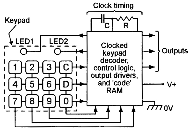
FIGURE 11. Basic elements of a key-pad security switch.
The switches are (in this example) arranged in four vertical and three horizontal columns, which are wired to a clocked decoder and control logic network that converts each digit keystroke into a four-bit binary code, and compares it with the four-bit code that is stored in the matching line of the system’s RAM. If the entire code number (which is usually four to eight digits long) is typed in without error, the switch opens and performs a useful function (opens a door or gives access to an engine’s start-up system, etc.), but if the correct code is not entered within three attempts, the lock automatically goes into a time-controlled shut-down or alarm mode.
In the above system, the secret code number can be changed at any time by simply typing in the existing code, pressing the ‘C’ switch once (to gain direct access to the RAM), typing in the new code number, and then pressing the ‘C’ switch again (to return to normal operation). The entire keyswitch can be disabled (for a time-controlled period) or re-enabled at any time by operating the ‘D’ switch, which gives a toggling disable/enable type of action; the keypad switch’s operating mode is displayed at all times via the two state-indicating LEDs.
DIGITAL TIME SWITCHES
Figure 12 shows a symbolic representation of a digital time-operated SPST electric switch, in which the switch arm is controlled via accurately-timed digital circuitry, and can be programmed to turn on and off at any desired times of the day or week.
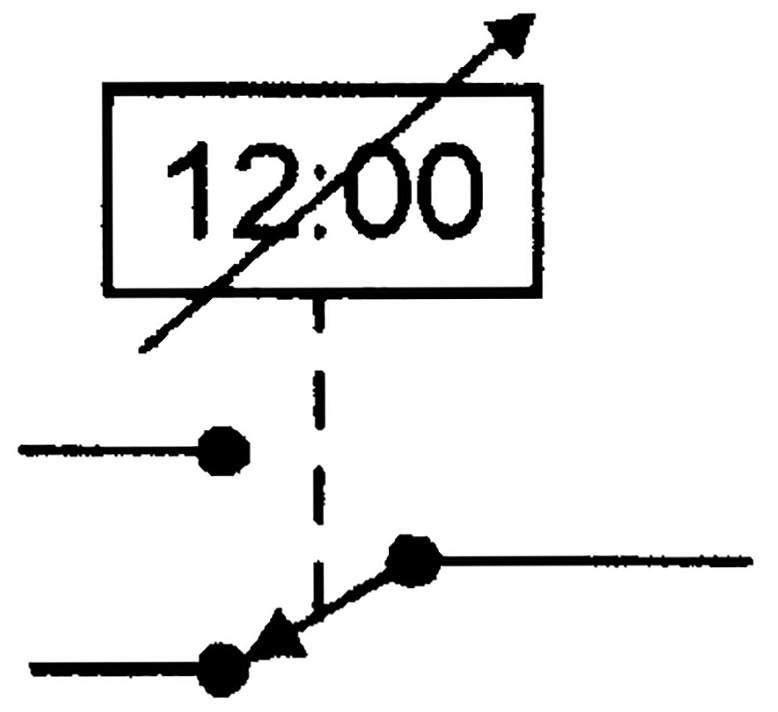
FIGURE 12. Symbolic representation of a digital time-operated SPST electric switch
Digital time switches offer far greater precision than normal analog types, and are used in many light-switching and solenoid-operating security applications.
MISCELLANEOUS ELECTRONIC SENSORS
A variety of special-purpose electronic sensors of value in security applications, but not so-far mentioned in this section, are also available from some specialist dealers. Amongst the most useful of these are radioactive ‘smoke detector’ elements that respond to various ionized particles, humidity sensors, strain gauges, Hall-Effect devices that respond to magnetic field strength (flux density), and ‘gas’ sensors that react to gases such as propane, butane, methane, isobutane, petrolium gas, natural gas, and ‘town’ gas. A few of these devices are described in some detail in later episodes of this series.
DATA LINKS
Data links are (apart from the actual signal processing unit) one of the three major elements of any electronic security system, the other two elements being the sensing unit(s) and the response unit.
All practical security systems use at least two data links (see last month’s Figure 1), which may have individual lengths ranging from less than one millimeter to many thousands of kilometers, depending on the specific application.
Most data links fit into one or another of three basic types, being either hard-wired types, opto-coupled types, or wireless types, as described in the rest of this DATA LINKS section.
HARD-WIRED DATA LINKS
Most hard-wired data links take the form of a length of multi-cored cable, used to link a sensor or response unit to the alarm system’s main control unit. Figures 13 to 15 show examples of such cables used to link a sensor switch to the input of a simple burglar alarm unit.
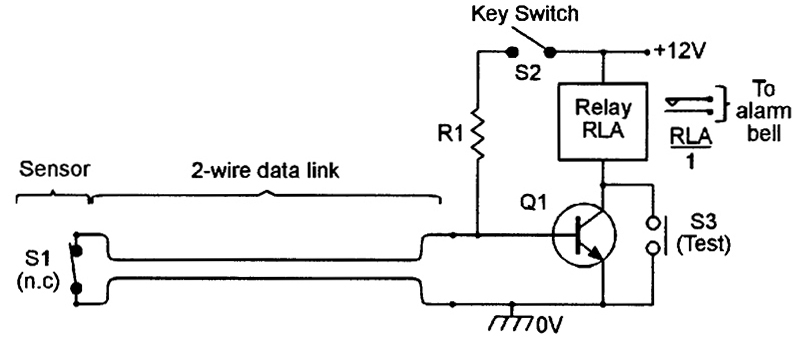
FIGURE 13. Two-wire data link used with a normally-closed sensor switch offers good security.
In Figure 13, the sensor switch is a normally-closed one of the type used to protect doors or windows and is connected to the unit via a two-wire (or two-core) data link; this circuit’s basic action is such that — when key switch S2 is closed — Q1 and the alarm both turn on if sensor switch S1 is opened or the data link is accidentally or deliberately cut. This circuit thus has an inherently good anti-tamper performance.
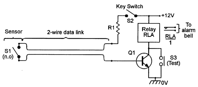
FIGURE 14. Two-wire data link used with a normally-open sensor switch offers very poor security.
In the Figure 14 circuit, the sensor switch is a normally-open type such as a pressure-mat switch, and is connected to the unit via a two-wire data link; this circuit’s basic action is such that — when key switch S2 is closed — Q1 and the alarm normally both turn on if sensor switch S1 is closed, but will fail to operate if the data link is accidentally or deliberately cut; this circuit thus has a poor anti-tamper performance.
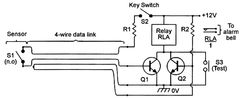
FIGURE 15. Four-wire data link used with a normally-open sensor switch offers excellent security.
Finally, Figure 15 shows a high-security version of the above circuit. In this case, the sensor switch is again a normally-open type such as a pressure-mat switch, but is connected to the unit via a data link that uses four wires, two of which serve an anti-tamper function; this circuit’s basic action is such that the alarm normally turns on via R1-Q1 if sensor switch S1 and key switch S2 are both closed, but operates instantly (even if key switch S2 is open) if the four-wire data link is accidentally or deliberately severed. This circuit thus has an excellent anti-tamper performance and is often used in department stores and other places in which the public has easy access to parts of the alarm system.
OPTO-COUPLED DATA LINKS
Opto-coupled data links are often used in applications where it is not possible or convenient to use a hard-wired data link, and come in three basic types, being either infrared ‘light-beam’ types, fiber optic ‘light guide’ types, or laser beam types.
Light-beam types are used mainly in short-range (less than six meters) remote control applications, but can — if used with a good lense system — be effective at ranges up to about 20 meters. Units of the latter type are sometimes used (in domestic applications) as a data link between a shed or other remote building’s intrusion sensor and a main alarm unit.
Fiber optic light guide data links are used mainly in applications where the link is fairly long (greater than 10 meters) and needs a wide signal bandwidth.
Laser beam data links are used mainly in medium-range applications in which it is not possible to use a hard-wired data link. They are sometimes used (illegally) in remote eavesdropping applications, in which the beam is bounced off of the window of a room in which a secret conversation is taking place, the return beam being modulated by the window’s acoustic pick-up signals.
WIRELESS DATA LINKS
Wireless data links — usually operating at 418MHz or 458MHz — are widely used in modern domestic burglar alarm systems (see last month’s Figure 5) to link the system’s various sensors to the main control unit, thus greatly easing installation problems and enabling the system to be remote-controlled via a small key-fob signal transmitter.
Most systems of this type have typical control ranges of up to 30 meters, but some sophisticated systems can be interfaced with both the domestic heating control unit and with the normal telephone system, enabling alarm and heating systems to be remotely monitored or controlled over a range of thousands of miles.
The owner of such a system can — while on holiday or working abroad — use a fixed or mobile ‘phone to check the home’s security at any time, or can use it to remotely turn on the building’s central heating system prior to eventually returning home.
ALARM RESPONSE UNITS
Alarm response units are the final major elements in any electronic security system, and usually take the form of a simple relay, some type of electromagnet, a solenoid- or motor-operated mechanism, or (in burglar alarm and other high-level security systems) a sound-generator and/or a light strobe unit. Brief details of units of these types are given in the rest of this ALARM RESPONSE UNITS section.
RELAY RESPONSE UNITS
Relays are electrically-operated switches that can be used to activate virtually any external electrical devices (such as lamps, sirens, motors, etc.).
Relays come in two basic types, one being the ‘reed’ type that was shown in last month’s Figure 12(a), and the other being the conventional electromagnetic type that takes the basic form shown in this month’s Figure 16.
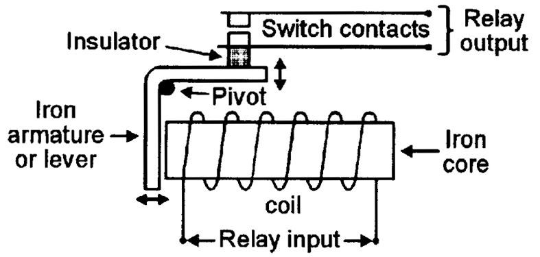
FIGURE 16. Basic design of a standard elecromagnetic relay.
Here, a multi-turn coil is wound on an iron core to form an electromagnet that can move an iron lever or armature which, in turn, can close or open one or more sets of switch contacts. The operating coil (which requires only a modest operating current) is electrically fully isolated from the switch contacts (which can control fairly high currents), and can be shown as separate elements in circuit diagrams, as shown in Figure 17, which represents a relay with a 12V, 120R coil, and a single set of normally-open (n.o.) switch contacts.
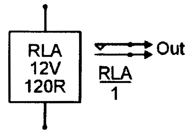
FIGURE 17. Representation of a 12V, 120R relay with one set of n.o. contacts.
Relays with a single set of n.o. contacts are usually used in the basic non-latching mode shown in Figure 18(a), in which the relay closes when S1 is closed and opens when S1 is opened. Relays with two (or more) sets of n.o. contacts can also be used in the self-latching mode shown in Figure 18(b), in which n.o. contacts RLA/2 are wired in parallel with S1 so that they close and lock (latch) the relay on as soon as S1 is closed. Once the relay has locked on, it can be turned off again by briefly breaking the supply connections to the relay coil.
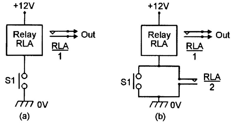
FIGURE 18. Relay switch used in (a) non-latching or (b) self-latching modes.
Relay coils are highly inductive and may generate back-EMFs of hundreds of volts if their coil currents are suddenly interrupted. These back-EMFs can easily damage switch contacts or solid-state devices connected to the coil, and it is thus often necessary to ‘damp’ them via protective diodes, as shown in Figures 19.
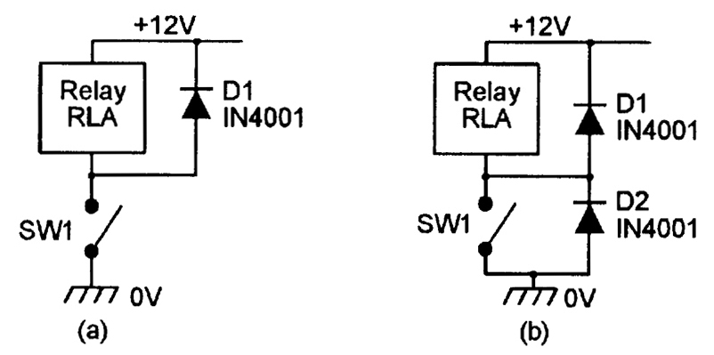
FIGURE 19. Relay coil using (a) single-diode or (b) two-diode coil damper.
In Figure 19(a), the coil damping is provided via D1, which prevents switch-off back-EMFs from driving the RLA-SW1 junction more than 600mA above the positive supply line. This form of protection is adequate for normal switching applications.
In Figure 19(b), the damping is provided via two diodes that stop the RLA-SW1 junction swinging more than 600mV above the positive supply rail or below the zero-volts rail. This form of protection is recommended for all applications in which SW1 is replaced by a transistor or other solid-state switching device.
ELECTROMAGNET UNITS
Electromagnet units are widely used in industrial and commercial applications to control the hold or release actions of security doors and safety guards and gates, etc. Figure 20 illustrates basic electromagnet operating principles.
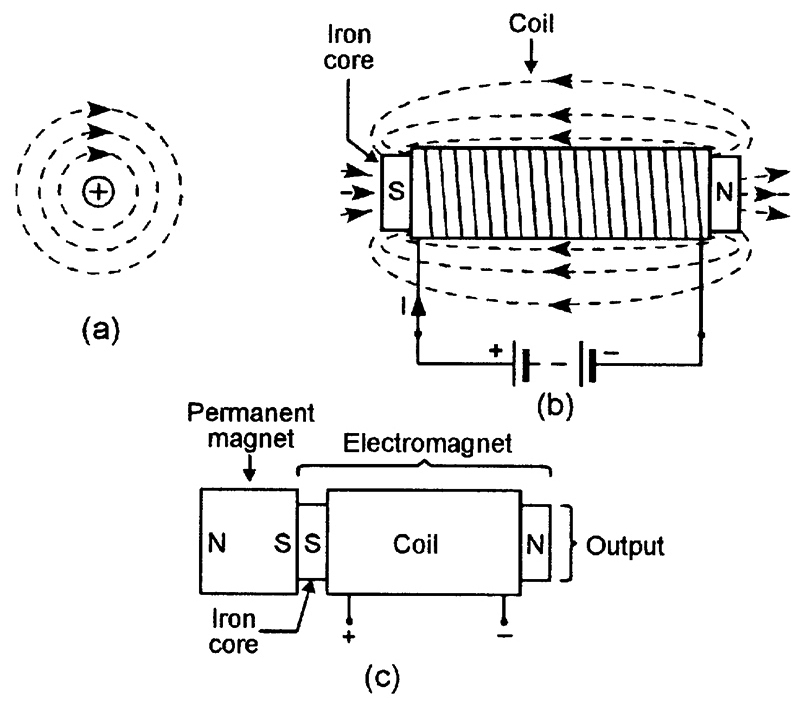
FIGURE 20. Diagrams showing the magnetic fields generated by (a) a current-carrying wire and (b) an electromagnet, and the basic construction of (c) an energize-to-release type of holding magnet.
When a current is passed through a wire, a magnetic field is generated about the axis of the wire, as shown in the cross-sectional view in Figure 20(a). When such a wire is wound as a coil on an iron-cored former, the fields of the individual turns interact in the way shown in Figure 20(b), causing the core to act like a normal bar magnet (with north and south poles) when the coil is energized, but to act like a piece of non-magnetic iron when the coil is not energized. This basic type of electromagnet is thus used in energize-to-hold applications.
Figure 20(c) shows a useful variant of the normal electromagnet. Here, a permanent magnet is fixed to one end of the electromagnet’s iron core, in the polarity shown in the diagram, and the other end of the core forms the output of the unit.
When the electromagnet is not energized, its iron core acts as a simple extension of the permanent magnet, with its output acting as the southern pole of the magnet, but when the electromagnet is energized, its magnetic field opposes that of the permanent magnet, and (if the two opposing fields are of equal strength) the unit’s output is thus demagnetized. This type of unit thus acts as an energize-to-release type of holding magnet.
SOLENOID-OPERATED UNITS
Solenoids are electromagnetic devices that are designed to move an iron ram or an armature and thereby activate a device such as a power switch, a safety latch, or a control valve or tap, etc. They consist — in essence — of a multi-turn coil that is wound about the axis of a fixed or moving iron core.
Fixed-core types act as simple electromagnets that move an external iron armature when the coil is energized; the best known example of this type of unit is the standard electromagnetic relay shown in Figure 16.
In moving-core types of solenoid, the coil is wound on a plastic or waxed-paper tube in which the iron core (which usually takes the form of a ram) is free to move; the basic action of this type of unit is such that center-of-mass of the iron core (ram) is forced into a central position within the coil when the coil is energized, but may be forced into a different position (via a spring, etc.) when the coil is not energized.
Moving-core solenoids come in several basic variants, and the three most widely used of these are shown in Figure 21.
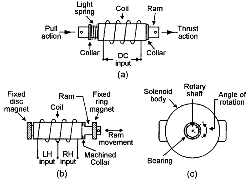
FIGURE 21. Simplified diagrams of (a) a conventional moving-core linear solenoid, (b) a magnetically latching split-coil moving-core linear solenoid, and (c) a rotary solenoid.
The most widely used type gives a simple linear movement of the ram, as shown in Figure 21(a). Here, the ram is normally biased to the left-of-center of the coil by two collars and a spring, but is forced to the right (to the coil’s central position) when the coil is energized, thus giving a thrust action at the right-hand end of the ram and a pull action at the left-hand end. Many practical solenoids of this basic type are designed to give only a thrust action or only a pull action.
A useful variant of the moving-core linear solenoid is the magnetically latching split-coil type shown in Figure 21(b). Here, when a pulse of energizing current is fed to the right-hand (RH) side of the split coil, the ram is forced to the right until a machined collar makes contact with a fixed ring magnet, which latches the ram in that position when the coil is de-energized.
Once the ram has latched into this position, it can only be unlatched by feeding a pulse of energizing current to the left-hand (LH) side of the coil, thus forcing the ram to the left until its left face makes contact with a fixed disc magnet, which latches the ram into this alternative position, and so on.
Magnetically-latching solenoids are useful where low mean power consumption is required. Note that simple split-coil solenoids are widely used as points-controllers in model railway systems, but do not incorporate magnetic latching.
Finally, the third type of moving-core solenoid is the rotary movement type shown in Figure 21(c), in which the solenoid’s linear action is converted into rotary form via a simple crank or link mechanism. These units typically give maximum shaft rotation angles in the range of 45° to 95°.
BELLS AND BUZZERS
Electric bells and buzzers are widely used sound-generating alarm response units. Figure 22 shows their typical basic construction and electrical equivalent circuit.
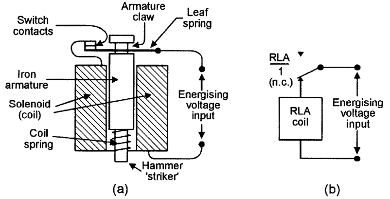
FIGURE 22. Typical basic construction (a) and equivalent circuit (b) of an electric bell or buzzer.
They consist of an iron armature that can move freely within a solenoid that can be energized via a pair of normally-closed switch contacts and a leaf spring.
Normally, the armature is forced out of the solenoid by a light coil spring. When a suitable energizing voltage is connected to the circuit the solenoid pulls the armature downwards until its hammer striker hits a sounding board (in a buzzer) or metal dome (in a bell). At this point, a claw at the other end of the armature pulls open the switch contact via the leaf spring, and the armature shoots outwards again under the pressure of the coil spring until the switch contacts close again and the process then repeats add infinitum.
Electric bells and buzzers are thus self-interrupting inductive devices. Electric bells have their acoustic output energy concentrated into a narrow ‘tone’ band and are thus reasonably efficient, but electric buzzers generate a broad ‘splurge’ of sound and are very inefficient.
MOTOR-OPERATED UNITS
Electric motors are widely used in industry and commerce to give automatic operation of safety and security doors, and to automatically operate customer-access doors and gates under approved safety/security conditions.
SOUND-GENERATOR/LIGHT-STROBE UNITS
All emergency-warning security and safety systems should (ideally) by fitted with an efficient attention-grabbing sound-generator system, to warn all and sundry of the existance of the emergency state, and with some form of light-strobe unit, to visually indicate the precise source of the emergency signals.
In buildings, the sound-generator may take the form of an electromechanical alarm bell or a piezoelectric or horn-speaker based electronic siren, and the visual warning may come from a special light-strobe. In automobiles, the sound-generator may take the form of a siren or a unit that pulses the vehicle’s horn, and the visual warning should be obtained by flashing the vehicles lights.
In all cases, the alarm-condition indicator unit must be fitted with an automatic timing mechanism that shuts it down after a pre-set period (typically less than 15 minutes) of operation.
In burglar alarm systems, the sound-generator and light-strobe units should be fitted together in a special alarm box and mounted high up on an external wall that (ideally) faces onto a well-used street or passageway. The box should have a built-in back-up battery that is charged via the system’s control panel cables, and the unit should automatically activate the alarm if this cable is cut. The alarm box should be fitted with some form of microswitch that automatically activates the alarm if any attempt is made to open its front cover or pull it from the wall. Units of this type are readily available from electronic alarm system suppliers. NV