
Contact-operated security circuits are units that are activated by the opening or closing of a set of electrical contacts. These contacts may take the form of a simple push-button switch, a pressure-pad switch, or a magnetically-activated reed switch, etc.
The security circuit’s output may take the form of some type of alarm-sound generator, or may take the form of a relay that can activate any external electrical device, and may be designed to give non-latching, self-latching, or one-shot output operation.
Contact-operated security systems have many practical applications in the home, in commercial buildings, and in industry. They can be used to attract attention when someone operates a push switch, or to give a warning when someone opens a door or treads on a pressure pad or tries to steal an item that is wired into a security loop, or to give some type of alarm or safety action when a piece of machinery moves beyond a preset limit and activates a microswitch, etc.
A wide range of practical contact-operated security circuits are described in this article.
BELL AND RELAY-OUTPUT CIRCUITS
CLOSE-TO-OPERATE CIRCUITS
The simplest type of contact-operated security circuit consists of an alarm bell (or a buzzer or electronic ‘siren-sound’ generator, etc.), wired in series with a normally-open (n.o.) close-to-operate switch; the combination being wired across a suitable battery supply, as shown in the basic ‘door-bell’ alarm circuit of Figure 1.
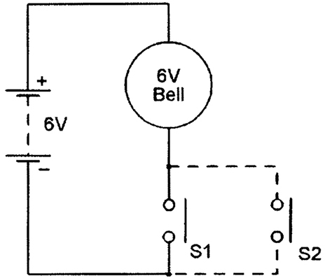
FIGURE 1. Simple door-bell type close-to-operate alarm circuit.
Note that any desired number of n.o. switches can be wired in parallel, so that the alarm operates when any of these switches are closed. This type of circuit gives an inherently non-latching type of operation, and has the great advantage of drawing zero standby current from its supply battery.
A disadvantage of the basic Figure 1 circuit is that it passes the full ‘alarm’ current through the n.o. operating switches and their wiring, so the switches must be fairly robust types, and the wiring must be kept fairly short if excessive wiring volt-drops are to be avoided. This latter point is of particular importance in security applications in which the circuit is used with several widely separated n.o. switches.
The solution to this problem is to activate the bell, via a ‘slave’ device (which is fitted close to the bell but requires a fairly low input current), and to activate this slave device (and thus the bell) via the security switches. Figures 2 to 6 show a variety of such circuits, in which the slave device takes the form of a relay, a power transistor, or an SCR.
Figure 2 shows a relay-aided version of the close-to-operate alarm circuit. Here, the parallel-connected n.o. switches are wired in series with the coil of a 6V relay (which typically draws an operating current of less than 100mA), and the relay contacts (which can typically switch currents of several amps) are wired in series with the alarm bell, and both combinations are wired across the same 6V supply.
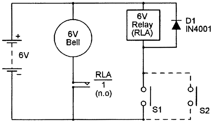
FIGURE 2. Relay-aided non-latching close-to-operate alarm.
Thus, when the switches are open, the relay is off and its contacts are open, so the bell is off, but when any one or more of the switches are closed, the relay is driven on and its contacts close and activate the alarm bell. Note in the latter case that the switches and their wiring pass a current equal to that of the relay coil; the switches can thus be fairly delicate ones, such as sensitive reed types, and the wiring can be reasonably long. Silicon diode D1 is wired across the relay’s coil to protect the switches against damage from the coil’s switch-off back EMF.
The Figure 2 circuit gives a non-latching form of operation, in which the alarm operates only while one or more of the operating switches are closed.
In most high-security applications, the circuit should be a self-latching type in which the relay and alarm automatically lock on as soon as any one of the n.o. switches is closed, and can only be de-activated via a security key.
Figure 3 shows the above circuit modified to give this type of operation. Here, the relay has two sets of n.o. contacts, and one of these is wired in parallel with the n.o. switches so that the relay self-latches as soon as it is operated, and the entire circuit can be enabled or disabled/de-activated via key switch S1, which is wired in series with the battery supply line.
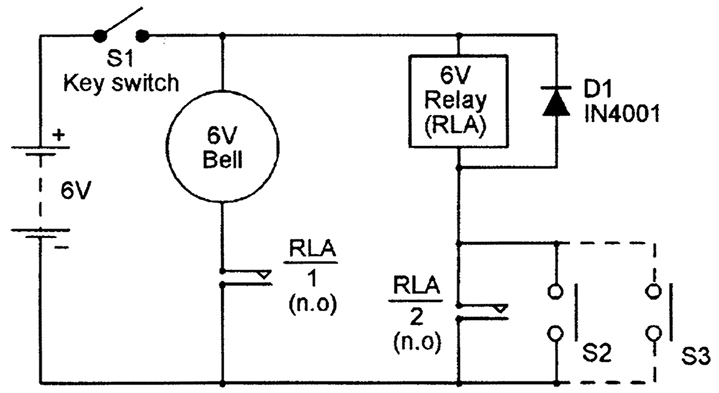
FIGURE 3. Relay-aided self-latching close-to-operate security alarm.
Circuits of this basic type are usually used in low-cost ‘zone protection’ applications, in which the ‘zone’ is a large room or shop floor, the S1 key switch is located outside of the zone, and the n.o. trigger switches are hidden pressure-mat switches or door- or window-operated microswitches fitted within the protected zone.
An alternative solution to the Figure 1 switch-and-wiring ‘current’ problem — but which can only be used in non-latching applications — is shown in Figure 4, in which npn power transistor Q1 is used as the slave device. Resistor R1 ensured that — when any of the activating switches are closed — Q1’s drive curent is limited to less than 60mA, which (assuming that Q1 has a nominal current gain of at least x25) enables the transistor to switch at least 1.5A through the alarm bell.
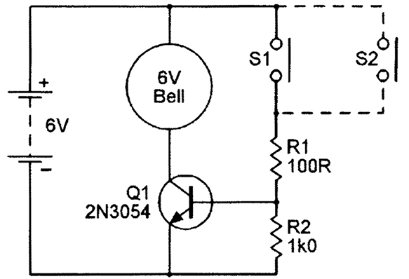
FIGURE 4. Transistor-aided non-latching close-to-operate alarm.
Another solution to the ‘current’ problem is to use an SCR (silicon controlled rectifier) as the slave device, as shown in Figures 5 and 6. These circuits rely on the fact that ordinary electromagnetic alarm bells are self-interrupting solenoid devices that incorporate a self-activating on/off switch in series with the solenoid’s supply line.
This switch is normally closed, allowing current to reach the solenoid and throw out a striker that hits the bell dome and simultaneously opens the switch, thus breaking the current feed and causing the striker to fall back again until the switch closes again, at which point the whole process starts to repeat, and so on; the bell’s operating current is thus drawn in pulsed form.
In the Figure 5 circuit, the alarm bell is wired in series with an SCR that has its gate current derived from the positive supply line via current-limiting resistor R1 and via the parallel-connected n.o. security switches, which (when R1 has a value of 1k0) pass operating currents of only a few milliamps. When all the switches are open, the SCR and alarm bell are off, but when any one of the switches is closed it feeds gate current to the SCR via R1, so the SCR turns on and activates the bell.
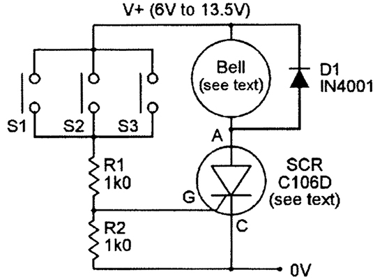
FIGURE 5. SCR-aided non-latching close-to-operate alarm.
Note in this design that, since the bell is a self-interrupting device, the circuit effectively gives a non-latching type of operation in which the SCR and bell only operate while one or more of the switches are closed.
Figure 6 shows how the above circuit can be modified to give self-latching operation. SCRs are inherently self-latching devices that, once they have been initially turned on, remain on until their anode current falls below a ‘minimum holding’ value, at which point the SCR unlatches and turns off.
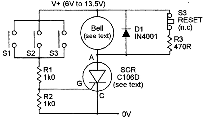
FIGURE 6. SCR-aided self-latching close-to-operate alarm.
In the Figure 5 circuit, the SCR thus automatically unlatches each time the alarm bell self-interrupts, but in the modified Figure 6 design, the bell is shunted via R3, which is wired in series with n.c. switch S4, which ensures that the SCR’s anode current does not fall below the C106’s minimum holding current value when the bell self-interrupts, thus providing the circuit with a self-latching action.
Note that the C106 SCR used in the Figure 5 and 6 circuits has an anode current rating of only 2A, so the alarm bell must be selected with this point in mind. Alternatively, SCRs with higher current ratings can be used in place of the C106, but this modification will probably necessitate changes in the R1 and R3 values of the circuits. Also note in these SCR circuits that — to compensate for the SCR’s typical 1V anode-to-cathode volt drop — the supply voltage must be at least 1V greater than the nominal operating voltage of the alarm bell.
OPEN-TO-OPERATE CIRCUITS
A major weakness of the Figure 1 to 6 circuits is that they do not give a ‘fail-safe’ form of operation, and give no indication of a faulty condition if a break occurs in the contact-switch wiring. This snag is overcome in circuits that are designed to be activated via normally-closed (n.c.) switches, and a basic circuit of this type is shown in Figure 7.
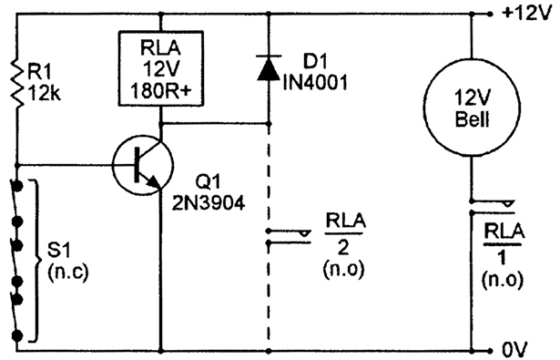
FIGURE 7. Simple open-to-operate alarm draws a 1mA standby current.
In Figure 7, the coil of a 12V relay is wired in series with the collector of transistor Q1, and bias resistor R1 is wired between the positive supply line and Q1 base. The alarm bell is wired across the supply lines via n.o. relay contacts RLA/1, and n.c. operating switch S1 (which may consist of any desired number of n.c. switches wired in series) is wired between the base and emitter of the transistor.
Thus, when S1 is closed, it shorts the base and emitter of Q1 together, so Q1 is cut off and the relay and the bell are inoperative.
Under this condition, the circuit draws a quiescent current of 1mA via R1. When S1 opens or a break occurs in its wiring, Q1’s base-to-emitter short is removed and the transistor is driven to saturation via R1, thus turning the relay on and activating the alarm bell via relay contacts RLA/1.
This basic circuit gives a non-latching type of alarm operation, but can be made to give self-latching operation by wiring a spare set of n.o. relay contacts (RLA/2) between the collector and emitter of Q1, as shown dotted in the diagram.
Thus, the Figure 7 circuit gives fail-safe operation, but draws a quiescent or standby current of 1mA. This standby current can be reduced to a mere 25µA by modifying the circuit in the way shown in Figure 8.
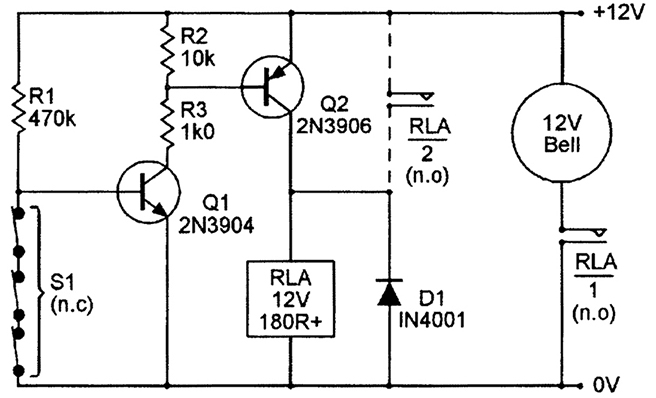
FIGURE 8. Improved open-to-operate alarm draws a 25µA standby current.
Here, the value of R1 is increased to 470K, and Q1 is used to activate the relay via pnp transistor Q2, and the circuit’s action is such that Q1-Q2 and the relay and bell are all off when S1 is closed, but turn on when S1 is open.
The basic circuit gives a non-latching form of operation, but can be made self-latching by wiring a spare set of n.o. relay contacts (RLA/2) between the collector and emitter of Q2, as shown dotted in the diagram.
If desired, the standby current of the Figure 8 circuit can be reduced to a mere 1µA or so by using an inverter-connected CMOS gate in place of Q1, as shown in Figure 9. The gate used here is taken from a 4001B quad two-input NOR gate IC, and the three unused gates are disabled by shorting their inputs to the 0V line, as shown in the diagram.
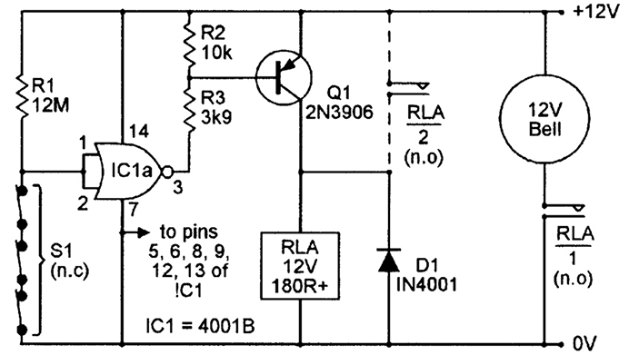
FIGURE 9. CMOS-aided open-to-operate alarm draws a 1µA standby current.
The used gate has a near-infinite input impedance, and the standby current of the circuit is determined mainly by the R1 value and by the leakage current of Q1. The basic circuit gives a non-latching form of operation, but can be made self-latching by wiring a spare set of n.o. relay contacts (RLA/2) between the collector and emitter of Q1, as shown dotted in the diagram.
Figure 10 shows an alternative way of making the basic Figure 8 circuit give self-latching operation, without resorting to the use of a spare set of n.o. relay contacts. In this case, the relay-driving transistor (Q1) is driven by a pair of 4001B CMOS NOR gates that are configured as a bistable multivibrator and has an output that goes low and self-latches if S1 is briefly opened or its leads are broken.
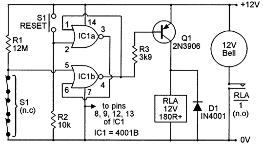
FIGURE 10. Self-latching CMOS-aided alarm draws a 1µA standby current.
As the bistable output goes low, it turns Q1 on, thus activating the relay and alarm bell. Once the bistable has latched the bell into the ‘on’ state, it can be reset into the standby or ‘off’ mode by closing S1 and momentarily operating RESET switch S2, at which point the bistable’s output latches back into the high state and turns off Q1 and the relay and bell. The circuit draws a quiescent current of about 1µA.
‘LOOP’ ALARM CIRCUITS
One type of contact-operated alarm circuit that is widely used in large shops and stores (and also in domestic garages and garden sheds) is the so-called ‘loop’ alarm, in which a long length of wire is run out from the alarm unit, is looped through a whole string of ‘to be protected’ items in such a way that none of them can be removed without cutting or removing the wire, and is then looped back to the alarm unit again, to complete a closed electrical circuit.
The alarm sounds instantly if an attempt is made to steal any of the protected items by cutting the wire loop, i.e., by effectively opening its ‘contacts.’ Figure 11 shows the circuit of a simple battery-powered unit of this type.

FIGURE 11. Simple self-latching loop alarm circuit.
The simple Figure 11 loop alarm circuit is a modified version of the self-latching CMOS-aided Figure 9 circuit, with its series-connected S1 security switches replaced by a number of series-connected wire ‘loops’ that — when key-operated switch S1 is closed — activate the self-latching alarm if any part of the loop wiring becomes open circuit.
In the diagram, only two loops are shown, but in practice any desired number of loops can be used. The entire circuit (except the loops) is housed inside a metal security case, and the loops are connected to screw terminals on the main circuit board via grommet holes in the side of the case; unwanted loops can be replaced by short circuits connected between the appropriate screw terminals. The entire circuit can be turned on and off via key switch S1.
Figure 12 shows an improved version of the Figure 11 self-latching loop alarm circuit. The first points to note about this version of the circuit are that a LED is connected across the relay coil via R4 and thus illuminates and gives a visual indication whenever the relay is turned on, and that the circuit’s +12V power feed is controlled via four-way key switch S1 and diodes D2 and D3. When S1 is in position ‘1,’ the entire circuit is turned off. When S1 is in position ‘2,’ the main part of the circuit (including the LED indicator) is active, but the alarm bell and self-latching facility are disabled. This TEST (non-latch) position is meant to be used when testing the loop wiring.
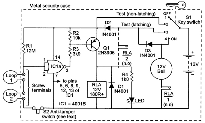
FIGURE 12. Improved version of the self-latching loop alarm.
When S1 is in the position ‘3’ TEST (latching) position, all of the circuit except the bell is enabled. When S1 is in the position ‘4’ ON position, the entire circuit (including the alarm bell) is enabled, and the circuit gives normal ‘security’ operation.
The final point to note about the Figure 12 circuit is that n.c anti-tamper switch S2 is wired in series with the loop network and (when S1 is set to the ON position) activates the self-latching alarm if it (S2) takes up an ‘open’ state.
S2 is actually an ordinary n.o. tactile ‘keypad’ switch with a short coil-spring bonded vertically to its touch-pad, and is fixed to the main circuit board in such a way that the switch is held in the closed n.c. position (via the spring) when the circuit’s security case is closed, but opens (thus sounding the alarm) if the case is opened while the alarm system is still turned on.
Anti-tamper switches of this basic type are quite easy to make from readily-available components. Figure 13 illustrates the basic method of construction.
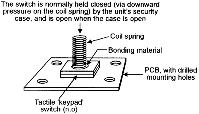
FIGURE 13. Basic way of constructing an anti-tamper switch (see text).
Before leaving this BELL AND RELAY-OUTPUT CIRCUITS section of this article, note that the various relay-output circuits shown in Figures 2, 3, and 7 to 11 can, if desired, be used to activate any type of electrical or electronic alarm or system via their n.o. relay contacts when the relay is triggered in response to an input contact-switching action, and are thus not restricted to use with alarm bells only.
SIREN-SOUND SECURITY CIRCUITS
Contact-operated security circuits can easily be designed to produce electronically-generated ‘siren’ alarm sounds in piezoelectric ‘sounders’ or in electromagnetic loudspeakers. Such systems can be made to produce a variety of sounds, at a variety of power levels, and may be designed around various types of semiconductor devices.
All siren-sound generators take the basic form shown in Figure 14, and consist of a siren waveform generator, an output driver, and an electro-acoustic transducer.
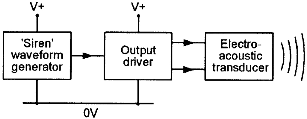
FIGURE 14. Basic elements of a siren-sound generator.
One of the cheapest and most useful semiconductor devices for use in this type of application is the CMOS 4001B quad two-input NOR gate IC, which draws near-zero standby current, has an ultra-high input impedance, can operate over a wide range of supply-rail voltages, and can be used in a variety of waveform-generating applications.
The rest of this article shows various ways of using one or two 4001B ICs and a few other components to make a variety of contact-operated siren-sound security circuits.
Figures 15 to 17 show three different ways of using 4001B ICs to make practical siren waveform generator circuits.
Figure 15 shows the basic circuit of a simple gated 800Hz (monotone) siren waveform generator. Here, two of the gates of a 4001B IC are connected as a gated 800Hz astable multivibrator, and the IC’s two remaining gates are disabled by wiring their inputs to ground.
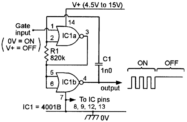
FIGURE 15. Basic 800Hz monotone ‘siren’ waveform generator circuit.
The action of this astable is such that it is inoperative, with its pin 4 output terminal locked high (at V+) when its pin 1 input terminal is high (at V+), but acts as a squarewave generator when its input pin is low (at 0V). The generator can thus be gated on and off via the pin 1 input terminal, and produces its output signal on pin 4. The astable’s operating frequency is controlled by the R1 and C1 values.
Figure 16 shows a single 4001B IC used to make a gated pulsed-tone waveform generator. Here, the two left-hand gates of the IC are wired as a gated low-frequency (about 6Hz) astable squarewave generator, and the two right-hand gates are wired as a gated 800Hz astable that is gated via the 6Hz astable.
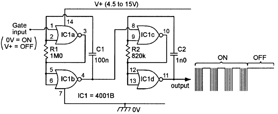
FIGURE 16. Basic pulsed-tone ‘siren’ waveform generator circuit.
The action of this circuit is such that it is inoperative, with its pin 11 output terminal locked high (at the positive supply rail voltage) when its pin 1 input terminal is high, but becomes active and produces a pulsed-tone output on pin 11 when its input pin is low (at 0V).
This generator can thus be gated on and off via the pin 1 input terminal and, when gated on, produces a 800Hz tone that is gated on and off at a 6Hz rate. The operating frequency of the 6Hz astable is controlled by R1-C1, and that of the 800Hz astable is controlled by R2-C2.
Figure 17 shows how the Figure 16 circuit can be modified so that it produces a warble-tone alarm signal. These two circuits are basically similar, but in the latter case the 6Hz astable is used to modulate the frequency of the right-hand astable (rather than to simply pulse it on and off), thus causing the generated tone to switch alternately between 600Hz and 450Hz at a 6Hz rate.
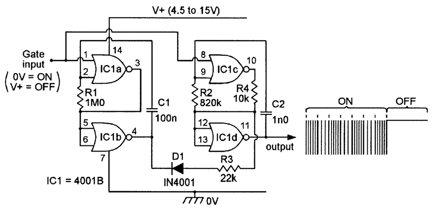
FIGURE 17. Basic warble-tone ‘siren’ waveform generator circuit.
Note that the pin 1 and pin 8 gate terminals of the two astables are tied together, and both astables are thus activated by the pin 1 ‘gate’ input signal; the circuit is inoperative, with its pin 11 output terminal locked high (at V+) when the pin 1 input terminal is high, but becomes active and produces a warble-tone output on pin 11 when the input pin is low (at 0V).
The operating frequency of this circuit’s 6Hz astable is controlled by R1-C1, the center frequency of the right-hand astable is controlled by R2-C2, and the ‘warble-tone’ swing of the right-hand astable is controlled via D1-R3.
Note that each of the Figure 15 to 17 gated waveform generator circuits are inactive (with their output terminal locked high) when their pin 1 input terminal is high (at V+), but can be gated on by pulling pin 1 low (to 0V).
Each of these circuits can thus be gated on and off by using any of the three input connections shown in Figure 18. Thus, they can be gated on by closing an n.o. switch by using the input connections shown in (a), or by opening an n.c. switch by using the input connections shown in (b), or can be gated on or off by making or breaking the supply line connection by using the input connections shown in (c). In cases (a) and (b), the circuit draws a typical standby current of only 1µA or so when in the ‘off’ state.
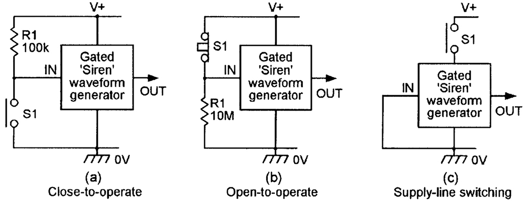
FIGURE 18. Alternative ways of gating the Figure 15 to 17 ‘siren’ waveform generator circuits.
If the Figure 15 to 17 gated waveform generator circuits are to be used in alarm-sound applications where fairly low acoustic output powers are required, these can be obtained by feeding the circuit’s output to a low-cost piezo sounder in any of the three basic ways shown in Figure 19.
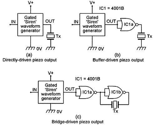
FIGURE 19. Alternative ways of driving a piezoelectric ‘sounder’ from the outputs of the Figure 15 to 17 ‘siren’ waveform generator circuits.
Thus, in (a), the sounder is driven directly from the generator’s output, and in (b), it is driven via a 4001B gate that is used as a simple inverting buffer; in both cases the RMS ‘alarm’ voltage applied across the piezo load equals 50% of the V+ value.
In (c), the sounder is driven in the ‘bridge’ mode via two series-connected 4001B inverters that apply anti-phase signals to the two sides of the piezo load, causing the piezo load to ‘see’ a squarewave drive voltage with a peak-to-peak value equal to double the V+ value, and an RMS ‘alarm’ signal voltage that equals the V+ value. The (c) circuit thus gives four times more acoustic output power than either of the (a) or (b) circuits.
If the Figure 15 to 17 gated waveform generator circuits (which each have an output that is locked high when the generator is gated off) are to be used in alarm-sound applications where fairly high acoustic output powers are required, these can be obtained by feeding the astable’s output to inexpensive ‘low-fi’ or horn-type loudspeakers (these have an electro-acoustic power conversion efficiency that is typically some 20 to 40 times greater than a normal hi-fi speaker) via one or other of the simple direct-coupled ‘driver’ circuits shown in Figures 20 to 22.
Thus, the simple Figure 20 driver circuit is designed to pump a maximum of only a few hundred milliwatts of audio power into a cheap 64R speaker. When the siren waveform generator is gated off, its output is high and Q1 is thus cut off, but when the generator is gated on, its output drives Q1 on and off and causes it to feed power to the 64R speaker. The output power depends on the supply rail voltage, and has a value of about 520mW at 12V, or 120mW at 6V, when feeding a 64R speaker load.
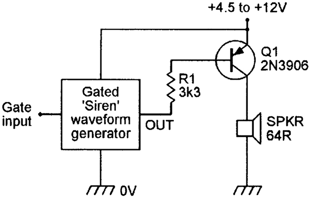
FIGURE 20. Simple output driver circuit that can feed up to 520mW into a 64R speaker load.
Note that, since Q1 is used as a simple power switch in this application, very little power is lost across the 2N3906 transistor, but its current rating (200mA maximum) may be exceeded if the circuit is used with a supply value greater than 12V.
The Figure 21 driver circuit can pump a maximum of 6.6 watts of audio power into an 8R0 speaker load, or 3.3 watts into a 16R load. Here, both transistors are cut off when the waveform generator is gated off, but are switched on and off in sympathy with the siren waveform when the generator is gated on.
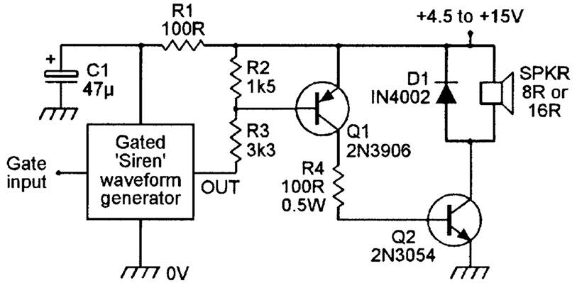
FIGURE 21. Medium power (up to 6.6 watts into 8R0) output driver.
Note in this circuit that the positive power supply rail is fed directly to the output driver, but is fed to the waveform generator via decoupling network R1-C1, that voltage divider R2-R3 ensures that the output stages are not driven on until the generator’s output voltage falls at least 1.9V below the supply rail value, and that diode D1 is used to damp the speaker’s back-EMF when driver Q2 switches off.
Finally, the Figure 22 driver circuit can pump a maximum of 13.2 watts into a 4R0 speaker load when powered from a 15V supply. Here, all three transistors are cut off when the waveform generator is cut off, but are switched on and off in sympathy with the siren waveform when the generator is gated on.
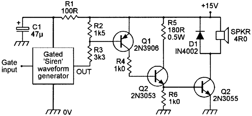
FIGURE 22. High power (up to 13.2 watts into 4R0) output driver.
Thus, Figures 15 to 17 show three alternative ‘siren’ waveform generator circuits that can — when used in practical contact operated security circuits — each be gated in any of three basic ways and be used in conjunction with any of six basic types of acoustic output driver circuit, thus offering a total of 54 different circuit combinations.
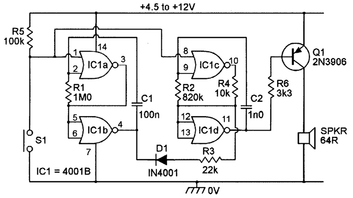
FIGURE 23. Low-power (up to 520mW) warble-tone alarm-call generator, activated by closing a n.o. switch.
Figure 23, for example, shows how the Figure 17, 18(a) and 20 circuits can be combined to make a warble-tone alarm-call generator that can be activated by closing an n.o. switch and which can pump 520mW into a 64R speaker load when operated from a 12V supply. NV