INTRODUCTION
Our last episode explained anti-burglary principles and described the basic operation of modern ‘hard-wired’ and ‘wireless’ burglar alarm systems. This episode starts off by briefly describing three basic categories of wireless burglar alarms and by looking at some basic types of intrusion sensors, and then goes on to describe a variety of practical hard-wired build-it-yourself anti-burglary circuits.
WIRELESS ALARM SYSTEM CATEGORIES
Domestic wireless burglar alarm systems vary greatly in price and performance, but can be roughly divided into the categories of ‘low-cost,’ ‘mid-range,’ and ‘top-of-the-range’ types. Figures 1 to 3 illustrate the basic features of typical examples of each of these system types.
The cheapest and most popular types of wireless burglar alarm system are those that give levels of protection that are quite adequate for use in small flats or apartments, but give only very basic protection when used in two or three bedroom houses. Figure 1 illustrates — in block diagram form — the basic features of a typical low-cost system of this type.
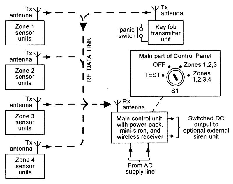
FIGURE 1. Block diagram showing the basic features of a typical ‘low-cost’ wireless burglar alarm system.
This system offers a total of four defense zones, but these are not individually selectable; in the unit shown, the user has the simple option of making either all four zones active (when the premises are empty), or of making all but one zone (Zone 4, the sleeping and bathroom areas) active (when the occupants are resting). The system gives no protection against burglars who enter the house while the occupants are watching TV, etc.
Systems of this type rely on the control unit’s built-in siren to scare off any intruders; often, they are not supplied with an external siren, but have provisions for driving an optional external siren that is powered by the control unit. Such sirens can be disabled by simply cutting their feed cables.
Figure 2 illustrates the basic features of a typical ‘mid-range’ wireless burglar alarm system that is designed for use in most houses and in small commercial premises. This system offers a total of six defense zones, all of which are individually selectable, and offers good protection against all types of burglar, including those who enter the house while the occupants are watching TV, etc.

FIGURE 2. Block diagram showing the basic features of a typical ‘mid-range’ wireless burglar alarm system.
Systems of this type are usually supplied complete with an internally-powered external siren/strobe unit that is cable-wired to the main control unit and is fully protected against tampering and cable-cutting, etc.
Finally, Figure 3 illustrates the basic features of a typical ‘top-of-the-range’ wireless burglar alarm system that is designed for use in large houses or medium-sized commercial premises. This system offers a total of 12 defense zones, all of which are individually selectable, and offers excellent overall protection.
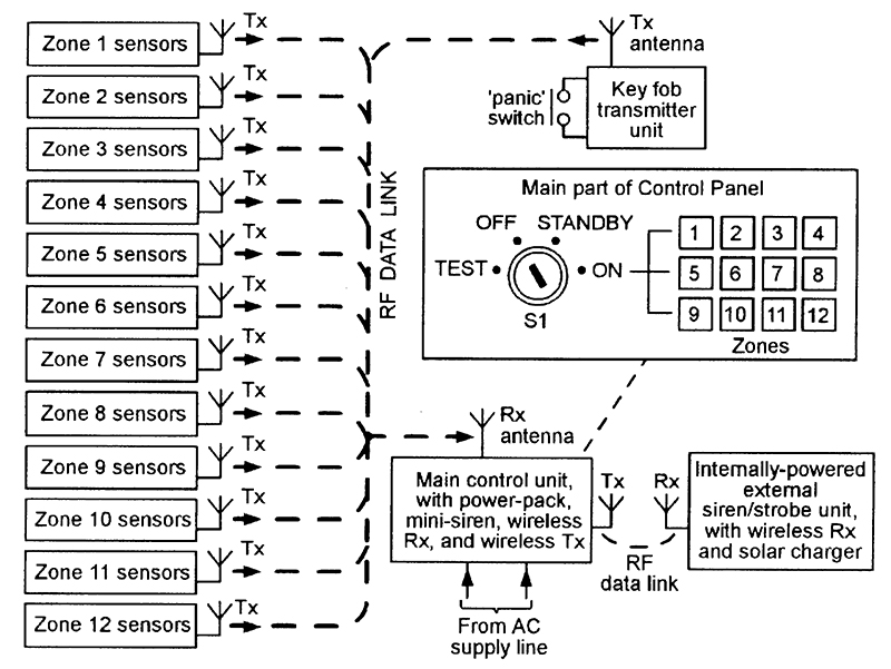
FIGURE 3. Block diagram showing the basic features of a typical ‘top-of-the-range’ wireless burglar alarm system.
The system shown is completely wireless, with no cable link between the main control unit and the external siren/strobe unit, which is wireless-activated (by the control unit), is fully protected against tampering, and is powered by an internal battery that is trickle charged by an integral solar panel.
INTRUSION SENSOR TYPES
The two types of intrusion sensor most widely used in modern domestic burglar alarm systems are PIR movement detectors for ‘area’ protection, and reed-and-magnet switches for ‘spot’ protection on doors and windows, etc.
Other types of sensor commonly used in domestic systems are pressure mat switches for spot ‘floor’ protection, vibration sensors to give ‘object’ protection, and window foil and glass break detectors to detect window breakage.
All of these sensors are similarly used in burglar alarm systems designed to protect commercial premises, which sometimes also use IR light beams or brittle wires — built into walls, floors, or ceilings — to detect break-ins via the building’s shell.
Note that modern PIR movement detectors are relatively inexpensive and have a high immunity to false alarms, and have consequently replaced once-popular but unreliable capacitive proximity detectors and microwave and ultrasonic movement detectors in most modern commercial ‘area’ protection systems.
Older readers may also note that once-popular ‘dual-purpose loop’ burglar alarm systems — in which all contact sensors are wired to a continuously-monitored loop that is fitted with an end-of-line resistor — are no longer used in the modern domestic security systems.
PRACTICAL BURGLAR ALARM CIRCUITS
INTRODUCTION
Modern microcontroller-based domestic burglar alarm systems are, like TVs and many other electronic ‘consumer’ products, so reasonably priced that few people would seriously consider DIY-building — rather than buying — such products. This is particularly true of wireless burglar alarm systems, which must use wireless Tx sections that have passed stringent tests laid down by a government testing/licensing authority.
It is, however, possible to cost-effectively DIY-build a variety of fairly simple and inexpensive ‘conventional’ burglar alarm and accessory circuits, and a number of these are described in the remaining sections of this article.
A ‘FALSE KEY’ BOOBY TRAP CIRCUIT
Some people hide a spare front door key under a flower pot or porch mat or on a porch ledge when they leave the house, and burglars often make a quick search for such a key when they enter the porch area of a house. ‘False key’ booby trap units take advantage of this fact by activating a semi-latching siren if an object such as a flower pot is briefly moved, or if someone grabs a key that is tied to a short length of string, etc. Figure 4 shows the practical circuit of such a unit.
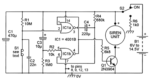
FIGURE 4. ‘False key’ booby trap alarm circuit.
In Figure 4, two gates of the 4001B CMOS IC are wired as a simple monostable multivibrator that gives a low pin 4 output when a positive voltage is fed to pin 5, but — if pin 5 is low — produces a positive pin 4 output pulse if a positive-going transition is applied to pin 2 by opening sensor switch S1.
This output pulse has a duration of about two minutes with the R4-C4 values shown, and is used to activate an inexpensive commercial siren unit via R5 and transistor Q1.
Note that the monostable can only be triggered by a positive-going transition of its pin 2 voltage; its action is not influenced by ‘standing’ high or low voltages applied to pin 2 via R1-S1. Thus, the action of this booby trap circuit — which may typically be housed in an inverted flower pot — is as follows:
When power is switched to the circuit via S2, C3-R3 apply a decaying positive voltage to pin 5 that disables the monostable for at least 12 seconds, thus giving the user time to safely ‘prime’ the circuit (position it so that S1 is held in the closed position) without activating the siren.
At the end of this period, the monostable becomes enabled. If sensor switch S1 subsequently opens for a period in excess of 200mS (determined by R1-C2), the monostable fires and activates the siren for a continuous period of about two minutes (which is long enough to scare off most burglars).
At the end of this two minute period, the siren turns off, irrespective of the state of S1, and can only be retriggered by closing and then opening S1 again.
Note that R6 discharges the circuit’s timing capacitors when control switch S2 is turned off, that most of the unit’s circuitry must be weatherproofed and protected with varnish, and that the unit can be powered by any 6V to 14.5V battery supply and the unit consumes a quiescent current of only a few µA (mainly via R1 and via C1’s leakage currents).
The circuit’s S1 switch can take various forms: in a flower pot unit it may be an n.o. keypad switch that is normally held closed by the weight of the pot, but opens when the pot is lifted; in another case, it may be an n.c. type that opens when someone tugs on a piece of string, and so on.
SHED/GARAGE BURGLAR ALARM CIRCUITS
Domestic workshops and garages that are fitted with AC power lines are best defended by simple AC-powered ‘house/flat’ types of burglar alarms that can activate powerful siren/light-strobe units for several minutes. A versatile alarm unit of this type is shown later in this article.
Most garden sheds and many domestic garages (and also caravans and small boats, etc.) are, however, devoid of AC power lines, and are best defended by battery-powered burglar alarms that, when activated, sound a siren for only a few minutes. This section looks at some practical circuits of this type.
Figures 5 to 8 show alternative versions of battery-powered shed/garage burglar alarms, which should ideally be powered by rechargeable batteries that are kept fully energized by solar-powered charger units. The Figure 5-6 unit is meant to be turned on and off by a key switch that is operated from outside the building; the Figure 7-8 unit is meant to be turned on and off from within the building, and incorporates exit/entry time delays that let the key holder leave and enter the building without sounding its alarms.
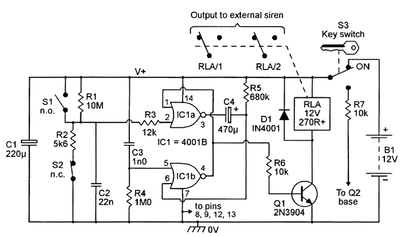
FIGURE 5. Shed/garage burglar alarm, with external on/off switch.
Each unit consumes a typical ON (‘standby’) current of 1-2µA, can use any desired number of n.o. (S1) and/or n.c. (S2) sensor switches, and has a pair of c.o. relay output contacts that latch on for about five minutes under the ‘alarm’ condition and can be used to activate any type of external siren, which may be self-powered or may be powered from the burglar alarm’s battery via the relay contacts.
Note in the Figure 5 and 7 diagrams that S1 can consist of any desired number of n.o. switches (including ‘tilt’ switches of the type used on up-and-over types of garage doors) wired in parallel, and S2 can consist of any desired number of n.c. switches (such as reed-and-magnet switches on shed doors and opening windows, anti-tamper switches built into alarm and siren boxes, wire ‘loops’ formed inside easily-cut cables, and cable loops used to protect tools, etc.) all wired in series. If S1 is not needed, simply omit it. If S2 is not needed, replace it with a short.
The Figure 5 burglar alarm circuit is turned on and off via key-operated switch S3, which is mounted in a position where it can be operated from outside of the building’s main entrance. Thus, S3 is used to enable the alarm after leaving the building, and to disable it before entering the building.
The circuit is basically similar to that of Figure 4, which uses two gates of a 4001B IC as a triggered monostable pulse generator. In this case, however, the monostable output has a period of about five minutes and activates relay RLA via transistor Q1, and can be triggered by closing n.o. switch S1 or by opening n.c. switch S2.
Figure 6 shows an optional audible-output ‘system-state’ indicator that can be added to the Figure 5 alarm circuit and emits a brief ‘bleep’ when the alarm circuit is first switched on, confirming that it is receiving power, and emits a longer ‘decaying’ bleep as the alarm circuit is switched off, confirming that its power has been removed (if you do not use this add-on circuit, change the R7 value to 1K0 and wire its low end to the 0V line).
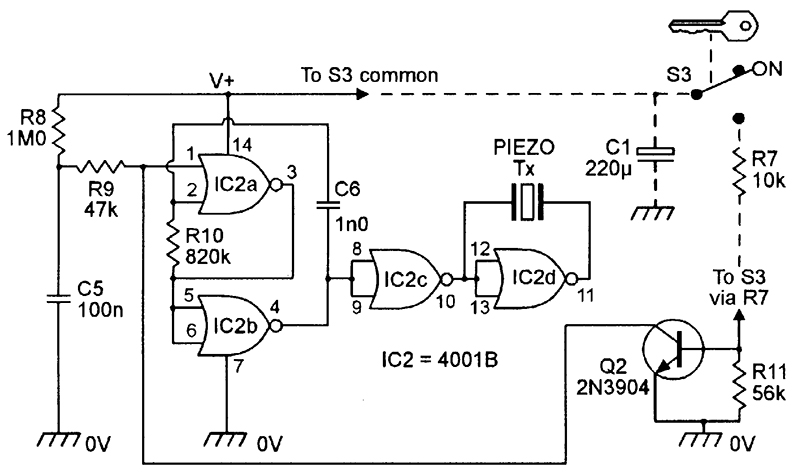
FIGURE 6. Optional state-indicating sounder, for use with the Figure 5 circuit.
In Figure 6, IC2 is wired as a gated astable that — when gated on by a ‘low’ voltage on pin 1 — generates an audible tone signal in a low-cost piezo sounder. The action is such that the astable is briefly driven on via R8-C5 as S3 is switched to the ON position, thus generating a brief ‘bleep’ in the sounder. When S3 is switched to the OFF position, C1’s stored charge drives the astable on via R7-Q1 and supplies the astable with limited operating power, thus producing a decaying ‘bleep’ in the sounder.
The Figure 7 burglar alarm circuit is turned on and off via key-operated switch S3, which is mounted inside the shed/garage; when S3 is first turned ON, an ‘exit delay’ comes into operation, giving the key holder about 18 seconds to leave the building, after which all S1/S2 sensor switches become fully active.
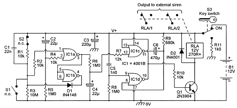
FIGURE 7. Shed/garage burglar alarm, with internal on/off switch.
When the building is re-entered after this period, the sensor switches trigger an ‘entry delay’ timer that — if S3 is not switched OFF within 18 seconds — triggers a five-minute monostable that drives an external siren via the contacts of relay RLA. The basic circuit is similar to that of Figure 5, except that exit/entry time-delay logic is interposed between the outputs of S1/S2 and the input trigger point of the five-minute monostable (IC1c-IC1d). The circuit operates as follows:
In Figure 7, IC1a is used as a NOR gate that gives a low (logic-0) pin 3 output if either input is high, and gives a high output only if both inputs are low. The pin 1 input of IC1a is normally high, but goes low if S1 closes or S2 opens. The pin 2 input of IC1a is normally low, but is held high by the C2-R5 ‘exit delay’ network for about 18 seconds when power is first applied to the circuit via S3. Thus, IC1a’s output is locked low during the ‘exit delay’ period, but can subsequently switch high if S1 closes or S2 opens.
If this latter action occurs, the output of inverter IC1b pulls IC1a’s pin 1 input low via D1, thus locking its output into the high state, irrespective of subsequent S1/S2 actions. This ‘high’ output is fed to the pin 12 ‘trigger’ input pin of the IC1c-IC1d relay-driving five-minute monostable via the R6-C4 ‘entry delay’ timing network, which triggers the monostable about 18 seconds after pin 3 goes high.
Figure 8 shows an optional audible-output ‘system-state’ indicator that can be added to the Figure 7 alarm circuit and emits a brief ‘bleep’ when the alarm circuit is first switched on prior to leaving the building, and emits a series of 50mS ‘bleeps’ at roughly one second intervals when anyone re-enters the building, reminding them to turn S3 OFF before the siren-activating finish of the ‘entry delay’ period.
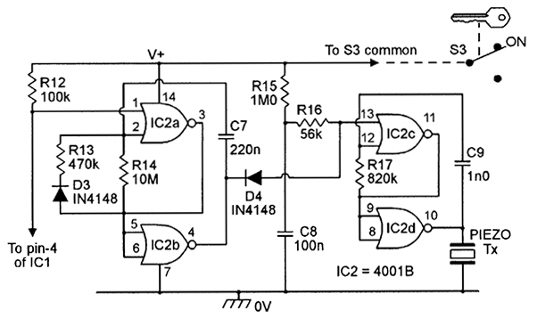
FIGURE 8. State-indicating sounder, for use with the Figure 7 circuit.
In Figure 8, IC2c-IC2d are wired as a gated astable that — when gated on by a ‘low’ voltage on pin 13 — generates an audible tone signal in a low-cost piezo sounder, and IC2a-IC2b are wired as a gated asymmetrical astable that gates the IC2c-IC2d astable via D4 and activates automatically when anyone re-enters the building.
The action is such that the IC2c-IC2d astable is briefly driven on via R15-C8 as S3 is switched to the ON position, thus generating a brief ‘bleep’ in the sounder, and is activated via the IC2a-IC2b astable whenever the main unit’s ‘entry delay’ circuitry becomes active, thus generating a series of 50mS ‘bleeps’ that are repeated at one second intervals until the main alarm unit is turned off via S3.
HOUSE/FLAT BURGLAR ALARM CIRCUITS
Shed/garage burglar alarms of the Figure 5 to 8 types are simple battery-powered single-zone units. Modern burglar alarms suitable for use in houses, flats, and apartments are moderately complex AC-powered multi-zone units with built-in ‘panic’ and ‘tamper’ facilities.
They usually have an internal trickle-charged battery that provides power in the event of an AC power-line failure, and have auxiliary 12V DC outputs suitable for powering external PIR movement detectors, etc.
Figures 9 to 13 show the block diagram and practical circuit details of a sophisticated modular ‘universal’ burglar alarm unit of the latter type that can quite easily be built to suit the precise needs of the individual user.
Figure 9 shows the basic block diagram of the ‘universal’ burglar alarm unit, which can be fitted with one exit/entry zone plus any desired number of ‘normal’ defense zones, all of which are individually switch-selectable.
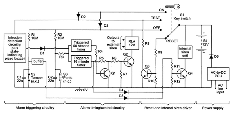
FIGURE 9. Block diagram of the ‘universal’ burglar alarm system.
Each zone is provided with its own audio/visual ‘state’ indicator (not shown in this diagram) and activates internal and external alarm sirens when an intrusion is detected. The unit can also be fitted with any desired number of n.c. ‘panic’ switches (S3) wired in series, and with any number of n.c. tamper switches or loops (S2) wired in series.
The unit comprises the four major sections shown in the diagram, and offers the following modes of operation, which are selectable via four-way key-switch S1:
ON. When S1 is in the ON position, all four major sections of the unit are energized, and the ‘alarm timing/control’ circuitry’s 50 second and 16 minute timers are immediately triggered if an intrusion is detected by the ‘alarm triggering’ circuitry, or if PANIC switch S3 is opened for more than 200mS.
Under this condition, the internal siren is immediately driven on via D4 and Q4, but the external siren (which is activated via Q2 and RLA) is held off for 50 seconds via R4-Q1, thus minimizing the chances of accidentally sounding the external alarm. Both alarms switch off when S1 is moved to the RESET position, or turn off automatically at the end of the 16 minute timing period. The intrusion detector’s piezo buzzer also sounds if an intrusion is detected and operates for the duration of the intrusion condition. The internal siren is driven on (via D5) if TAMPER switch S2 opens, and sounds for the duration of the o.c. condition.
TEST. When S1 is in the TEST position, the ‘alarm timing/control’ circuitry and the TAMPER and PANIC switches are disabled, but the intrusion detection circuitry is fully active; if an intrusion state is detected under this condition, only the internal piezo buzzer is activated. This mode is useful when testing or checking sensor switches, PIR units, or sensor wiring, etc.
OFF. When S1 is in the OFF position, the intrusion detection circuitry is disabled, but the TAMPER and PANIC circuitry is fully active. If TAMPER switch S2 opens, the internal siren is driven on (via D5-Q4) for the duration of the o.c. condition. If PANIC switch S3 opens, the internal siren is driven on immediately (via D4-Q4) and the external siren activates 50 seconds later. Both sirens turn off when S1 is moved to RESET, or turn off automatically at the end of the 16 minute timing period.
RESET. When S1 is in the RESET position, the entire circuit (except the power supply circuitry) is effectively disabled, and Q3 rapidly resets the intrusion detector circuit’s ‘exit delay’ timer.
Figure 10 shows the basic circuitry of the ‘universal’ alarm unit’s intrusion sensing/signal processing circuitry, specifically applied to a unit with one entry/exit zone (Zone ‘A’) and three ‘normal’ zones (Zones ‘B’ to ‘D’).
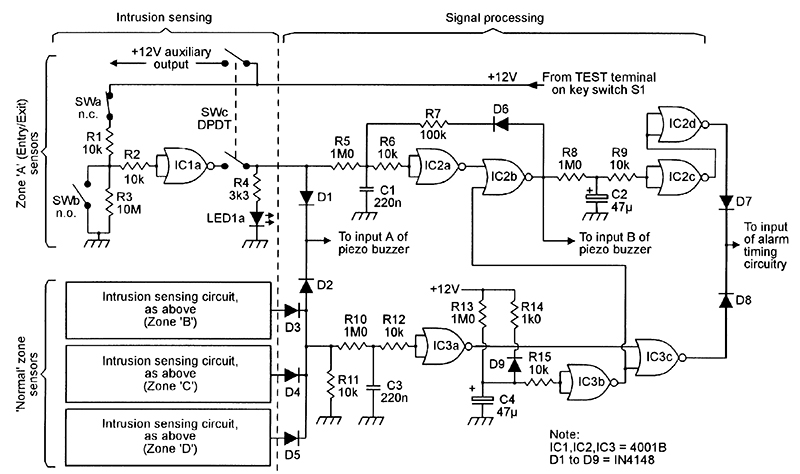
FIGURE 10. Basic circuit diagram of the intrusion sensing/signal processing circuitry.
Additional ‘normal’ zones can be added by simply duplicating the Zone ‘D’ and D5 circuitry for each extra zone. All zones use the same intrusion sensing circuit design as shown for Zone ‘A.’ Each zone can use any desired number of series-connected n.c. (SWa) and/or parallel-connected n.o. (SWb) sensor switches, and is selected by a DPDT switch (SWc) that — when closed — connects the output of inverting buffer IC1a to a state-indicating LED (LED1a) and also connects the +12V supply to any auxiliary units (PIRs, etc.) that are associated with the zone.
When a zone is selected by SWc and key switch S1, its action is such that the output of IC1a goes high and illuminates the LED and activates a piezo buzzer (via D1 or D2) if any of the zone’s intrusion-detecting sensor switches are activated. This ‘high’ signal is also passed through the unit’s signal processing circuitry, as described in the next two paragraphs.
In Figure 10, the output signals from the sensing circuits of all selected ‘normal’ defense zones are ORed via D3-D4-D5 and are then fed to input A (monotone sound) of the piezo buzzer via D2, and also through transient suppressor R10-C3 (which only passes signals that switch high for at least 200mS).
The output of R10-C3 is then inverted by IC3a and passed to one input of NOR-gate IC3c, which has its other input derived from 30 second switch-on delay generator R13-C4-IC3b, which disables IC3c for 30 seconds when power is first connected to the circuit via S1.
The net result is that the circuit gives an instant audio-visual indication if the output of any selected zone switches high but, under this condition, IC3b’s output only generates a siren-activating signal (via D8) if the circuitry has been energized via S1 for at least 30 seconds.
In Figure 10, the output signals from the entry/exit zone are (when SWc is closed) fed to input A of the piezo buzzer via D1, and also passed — via transient suppressor R5-C1 — to the input of a gated self-latching, non-inverting buffer formed by 1C2a-IC2b, which is gated by the R13-C4-IC3b 30 second switch-on delay generator, which provides the zone with its ‘exit’ delay.
If the zone’s output switches high during the 30 second exit delay period (as, for example, when someone exits the zone), the circuit gives an instant audio-visual indication of the fact but produces no other effects.
If the zone’s output switches high after the end of the 30 second exit delay period (as, for example, when someone re-enters the zone), the circuit again gives an instant audio-visual indication of the fact but, in this case, the output of IC2b switches high and is latched into that state via D6-R7.
This action drives input B (timing-beat sound) of the piezo buzzer high and also initiates a 30 second entry delay timing period (controlled via R8-C2 and non-inverting buffer IC2c-IC2d). If the complete circuit is not switched off (via S1) by the end of this 30 second ‘entry’ period, IC2d’s output switches high and activates the unit’s sirens via D7.
Note in Figure 10 that D9-R14 are used to rapidly discharge C4 via the positive supply rail and Figure 9’s transistor Q3 when S1 is moved to the RESET position. Also note, when building the Figure 10 circuit, that pin 14 of all 4001B ICs must be wired to the +ve supply rail, pin 7 to the 0V rail, and that all unused gate input pins must be tied to the 0V rail. All LEDs must be high-brightness types.
Figure 11 shows the circuit of the unit’s state-indicating piezo buzzer unit, which is powered from the supply rails of the intrusion sensing/signal processing circuitry and consists of two gated astables that are activated by high (logic 1) gate voltages.
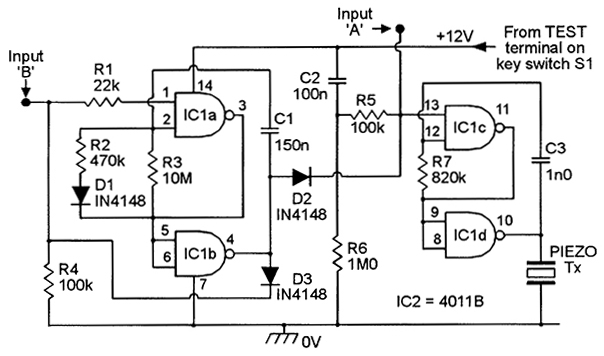
FIGURE 11. Circuit of the ‘universal’ burglar alarm’s state-indicating piezo buzzer unit.
IC1c-IC1d are wired as a simple ‘tone’ astable that — when gated on via pin 13 — generates a 680Hz tone in the piezo sounder, and IC1a-IC1b are wired as a gated semi-latching asymmetrical astable that — when gated on via the alarm’s ‘entry delay’ timer (see Figure 10) — produces one-per-second 50mS output pulses that gate the tone astable via D2.
The action is such that the tone astable is briefly driven on via C2-R6 when power is first switched to the circuit, thus generating a brief ‘switch-on’ bleep in the sounder, and is activated via the input ‘A’ terminal whenever a sensor switch is activated in any of the alarm’s active zone areas, and is also activated via the IC1a-IC1b astable and D2 whenever the alarm’s ‘entry delay’ circuitry becomes active, thus generating a series of 50mS ‘bleeps’ at roughly one second intervals when anyone re-enters the building, reminding them to turn keyswitch S1 OFF before the siren-activating finish of the ‘entry delay’ period.
Figure 12 shows the circuit of the alarm’s siren control unit, which is based on the block diagram of Figure 9 but uses its own component numbering system and is energized when S1 is in the ON and OFF positions.
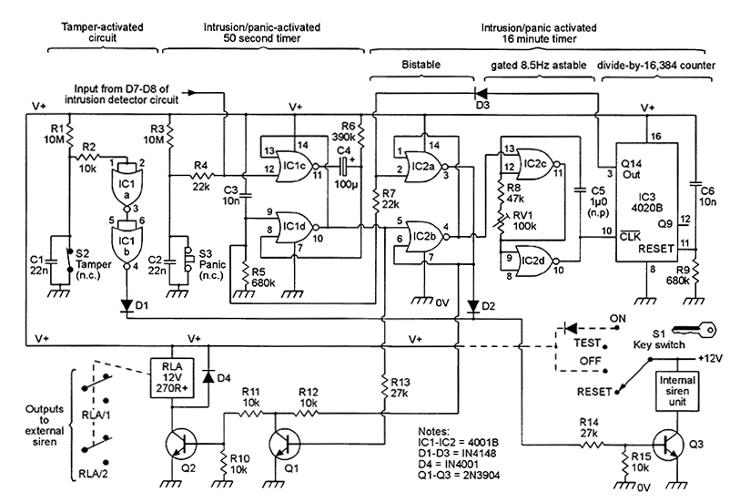
FIGURE 12. Circuit of the alarm’s siren control unit.
Here, IC1a-IC1b are wired as a non-inverting buffer that drives the internal siren on (via D1-Q3) if Tamper switch S2 opens, and the remaining ICs act as triggered 50 second and 16 minute timers that activate the internal and external sirens if Panic switch S3 is opened or if a ‘high’ input is received from the output of the alarm’s intrusion detector circuitry. These timing circuits operate as follows:
In Figure 12, IC1c-IC1d are wired as a simple monostable timer that controls the external siren’s ‘hold-off’ period; it is automatically reset at S1-switch-on via C3-R5 and is triggered by a positive-going transition on pin 12 (derived from the intrusion detector, or by opening S3).
When triggered, the monostable’s pin 10 output switches high and activates the IC2-IC3 16 minute timer and turns Q1 on, but switches low again at the end of its 50 second (nominal) timing period, which is controlled by R6-C4.
In practice, this timing period also depends on the ‘threshold’ voltage value of the individual IC, and may vary substantially from the 50 second value. If it does, make the timing roughly correct by changing the R6 value.
The output of the 50 second timer triggers the 16 minute timer, which is a semi-precision design built around a bistable latch (IC2a-IC2b), a gated 8.5Hz astable (IC2c-IC2d), and a 14-stage (divide-by-16,384) ripple counter (IC3). The action is such that, at switch-on, the bistable is automatically reset (with its pin 3 output low and pin 4 high) via C3-R5-R7, thus gating the astable off, and the counter is reset via C6-R9.
As soon as the 50 second timer (IC1c-IC1d) is triggered, its pin 10 output flips the IC2a-IC2b bistable, driving the internal siren on via D2-Q3 and feeding a drive current towards the base of relay-driving transistor Q2 via R12-R11, and also gating on the astable, which immediately starts feeding clock pulses into the IC3 counter at a 8.5Hz rate.
Note that, in the early stages of this 16 minute timing sequence, Q1 is driven on by the monostable timer, thus preventing the bistable’s drive current from reaching the base of Q2, but that Q1 turns off after 50 seconds, thus enabling Q2 to turn on and activate the external siren via relay contacts RLA/1-RLA/2.
Meanwhile, the astable keeps feeding clock pulses into the counter until, after 16 minutes, on the arrival of the 8192nd pulse, the pin 3 output flips high and resets the bistable via D3, thus terminating the timing process and turning both the internal and external sirens off.
The circuit’s timing period can easily be set to precisely 16 minutes by connecting a LED and 4k7 series resistor between pins 12 and 8 of IC3 and — with the timer triggered — carefully trimming RV1 so that the LED operates with precise 30 second on and off periods.
Figure 13 shows the circuit of the alarm’s ‘reset’ and internal siren driver circuitry, together with its connections to S1; this diagram is based on those of Figures 9 and 12, but uses its own component numbering system. Here, Q1 is driven on whenever S1 is in the RESET position, and rapidly resets the alarm’s intrusion detector ‘exit delay’ timer by discharging its timing capacitor (C4 in Figure 10).
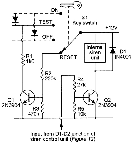
FIGURE 13. The alarm’s ‘reset’ and internal siren driver circuitry.
Q2 is driven on (via the output of the alarm timing/control unit) and activates the internal siren unit (a low-cost multi-tone medium power commercial unit) whenever an intrusion is detected or a tamper or panic switch is operated; the specified Q2 transistor has a maximum current rating of 200mA, which is adequate for driving most medium-power 12V sirens.
Regarding the ‘universal’ burglar alarm’s power supply, note that the basic unit consumes a typical standby current of only a few microamps and can, if desired, simply be powered by a rechargeable 12V battery. In practice, however, modern burglar alarms are usually used in conjunction with PIR detector units, each of which typically consume a quiescent current of 20mA.
Thus, a system that uses three PIRs consumes a quiescent operating current of about 60mA, which can — if desired — be supplied by a 12V rechargeable 1.2AH battery that is fed — via a protective diode — via the output current of a line-powered 60mA trickle charger.
In a unit of this type, the charger supplies the full operating current when the alarm is in its ON but untriggered mode; the battery supplies all excess power if the alarm is triggered, and receives a safe 60mA (1/20th of its 1.2AH capacity) trickle charge when the alarm is not in the ON state.
Finally, note that the ‘universal’ burglar alarm is very simple to operate, and is normally used in the ON mode when required to respond to an intrusion, and in the OFF mode (in which its Panic and Tamper switches are still active) when it is not required to detect an intrusion.
The TEST mode is only used when setting up or testing the system. The RESET mode is only used to reset the alarm timing/control circuitry once an alarm siren has activated, or to rapidly reset the intrusion detector’s exit delay timer when an unexpected repeat of the full ‘exit delay’ time is needed. NV