INTRODUCTION
Most of the previous episodes of this series have each looked at a specific class or type of electronic security circuit.
This time, we'll look at a miscellaneous collection of security circuits that can be used in the home or in commerce or industry, but which do not fit into any of the specific classes of circuits described in earlier articles.
These circuits include ones that are activated by the presence of a liquid, steam, or gas, by sound, by the failure of AC power supplies, by the close or near proximity of a person or object, by a human touch, or by the breaking of an ultrasonic beam.
Liquid- and Steam-Activated Circuits
BASIC PRINCIPLES AND CIRCUITS
Liquid- and steam-activated circuits have several practical applications in the home and in industry.
Liquid-activated circuits can be made to sound an alarm or activate a safety mechanism when the water in a bath or cistern or the liquid in a tank or vat reaches or exceeds (or falls below) a preset level, or when flooding occurs in a cellar or basement, or when an impact wave is generated as a person or object falls into a swimming pool or tank, etc.
Steam-activated circuits can be made to sound an alarm or activate a safety mechanism when high-pressure steam escapes from a valve or fractured pipe, or when steam emerges from the spout of a kettle or container as the liquid reaches its boiling point.
Impure water (including tap water, sea water, and most rain water, and steam) and many other liquids have a fairly low electrical resistance, but normal air has an ultra-high electrical resistance.
Consequently, one of the simplest electronic ways of detecting the presence or absence of conductive liquids (or vapors) is to use a pair of metal probes as sensors and to connect their outputs to a resistance-activated ‘switch’ circuit in the basic way shown in Figure 1.
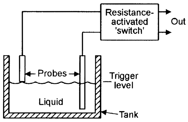
FIGURE 1. Basic ‘electronic’ way of detecting conductive liquids via a pair of metal probes.
Here, when the liquid is in contact with both probes simultaneously, the probe-to-probe resistance is relatively low and, under this condition, the output voltage of the resistance-activated switch is also low, but when the liquid is not in contact with both probes at the same time, their probe-to-probe resistance is very high and, under this condition, the output voltage of the switch is high. The circuit’s output can thus be used to activate an alarm or other device when the liquid (or vapor) is present or absent, or is above or below a preset level.
In practice, the resistance appearing across the probes under the ‘contact’ condition depends on the type of medium that is being detected. In the case of rain or tap water, it may typically be in the range of 1K0 to 10K when the probes are 10mm apart, but in the case of steam or many oils, the resistance may be several megohms or greater. On some applications, the metal container or tank that holds the conductive liquid can act as one of the two metal ‘contact’ probes.
Note that the above liquid-detection technique is not suitable for use with highly volatile, corrosive, or highly-resistive liquids. In such cases, the presence/absence of the liquid may best be detected by using an electromechanical method, such as that shown in Figure 2.
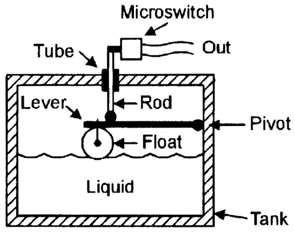
FIGURE 2. Basic ‘electromechanical’ way of detecting the critical level of a liquid.
Here, the liquid is contained in a sealed tank, and its level is sensed by a float that is anchored to a pivoted lever that drives a rod that passes out of the top of the tank via a close-fitting tube. The rod thus rises and falls in relation to the liquid level, and activates an external microswitch when the level goes above or below some preset limit.
Figure 3 shows a practical example of a simple non-latching liquid-activated circuit that operates a relay when a liquid with a resistance of less than about 500K contacts both probes simultaneously, e.g., when the water in a bath or cistern reaches a certain level. The circuit uses a 12V supply, and the relay’s RLA/1 contacts can be used to activate any type of external electrical device.
When the probes are open-circuit, Q1 and Q2 are cut off and the circuit consumes a standby current of less than 1µA, but when a resistance of less than about 500K is applied across the probes, sufficient current flows in Q1’s base to drive Q1-Q2 and the relay on.
Note that the sensitivity of the Figure 3 circuit can be reduced by simply reducing the value of R1; the maximum resistive sensitivity is roughly 18 x R1, and falls below 180K when R1 has a value of 10K, and below 60K at an R1 value of 3k3.
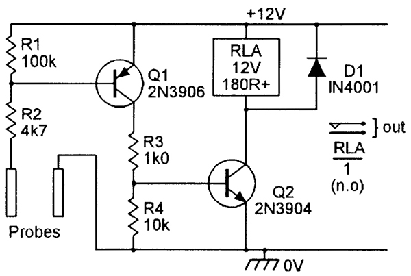
FIGURE 3. Simple relay-output ‘liquid-activated’ circuit operates when less than 500K is applied across the probes.
Conversely, the sensitivity can be greatly increased by raising the R1 value and using a super-alpha-connected pair of transistors in place of Q1, and Figure 4 shows how the above circuit can be modified in this way, so that it can be activated by probe resistances of up to 20M, e.g., by steam or high-resistance liquids.
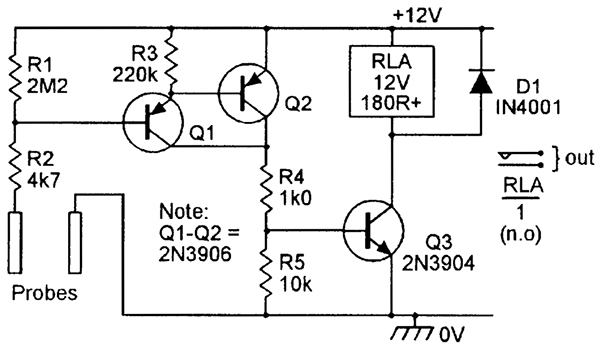
FIGURE 4. Sensitive relay-output ‘liquid-activated’ circuit operates when less than 20M is applied across the probes.
LM1830 IC CIRCUITS
When in use, liquid-level detector circuits of the simple types shown in Figures 3 and 4 pass a small DC current through the liquid under test. In theory, this DC current can result in an electroplating action in which metal slowly migrates from one probe to the other, eventually degrading the ‘source’ probe.
This problem does not occur if an AC test current is used, and a dedicated ‘fluid-level detector’ IC that uses this technique is widely available, at modest cost. The device is manufactured by National Semiconductor and is known as the LM1830. Figure 5 shows the outline and simplified internal circuit of the IC.

FIGURE 5. Pin notations and simplified block diagram of the LM1830 ‘fluid-level detector’ IC.
The LM1830 can be used to detect and indicate the presence or absence of water or any other liquid that presents a resistance of less than 100K between its pin 10 (detector input) and pin 11 (GND) ‘probe’ points.
The IC houses an oscillator (which gives AC drive to the water-detecting metal probe), a 13K reference resistor, a balance detector, and (available on pin 12) an open-collector npn common-emitter output stage that can sink up to 20mA maximum.
The oscillator frequency is set via an external capacitor (1n0 gives 7KHz operation) wired between pins 1 and 7, and the IC can operate from supplies in the 9V to 25V range and consumes a typical standby current of 5.5mA.
Figure 6 shows the LM1830 IC’s basic application circuits as a low-liquid-level alarm with an LED output; note that the (a) circuit uses two separate probes, one of which is grounded, but that in the (b) circuit — in which the liquid is stored in a metal tank — the metal storage tank is grounded and acts as one of the circuit’s two ‘probes.’ The IC’s internal oscillator is set at 7KHz via C1, and the non-grounded metal probe is taken to the pin 10 ‘detector’ input and is AC driven via C2 and the internal 13K reference resistor.
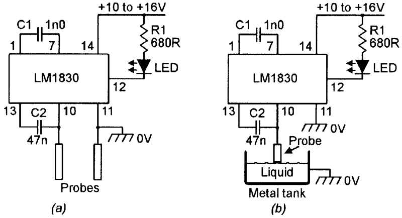
FIGURE 6. Basic LM1830 low-fluid-level warning circuit with LED output, using (a) separate probes and (b) a single probe.
When the liquid level is ‘high’ (i.e., in contact with the probe), the probe-to-ground resistance is below the 13K reference value and, under this condition, the output LED is off. When the liquid level is low, the probe-to-ground resistance is high (greater than the 13K reference value) and, under this condition, the output LED is driven by a 7KHz squarewave signal and thus illuminates. The basic Figure 6 circuit can be usefully modified in a variety of ways, as shown in Figures 7 to 10. Figure 7 shows it modified to give an audible 700Hz tone output (set by C1) into an inexpensive piezo sounder.
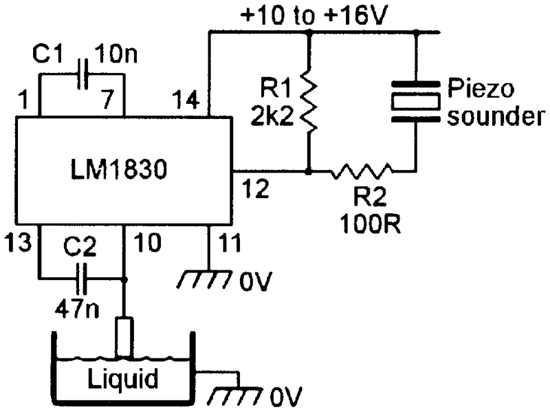
FIGURE 7. Low-fluid-level warning circuit with 700Hz tone output.
The LM1830 IC has a mean output current limit of 20mA maximum, and Figure 8 shows how the available output power can be boosted via an external emitter-follower stage, and also shows how the IC can be used with an external (rather than the internal) reference resistor of up to 100K maximum (1K0 minimum), to enable it to test liquids with resistance values of up to 100K.
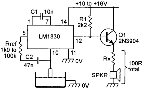
FIGURE 8. Low-fluid-level warning circuit with external reference resistor and boosted audio output.
Figure 9 shows the circuit modified to give relay output drive via pnp emitter-follower Q1, by using C3 to convert the output-stage driving signal to DC. This circuit also shows supply-line transient protection given to the IC via R1; this modification is recommended for use in automobile circuits, where — under very exceptional circumstances — supply transients may reach peak values of 40-50V.
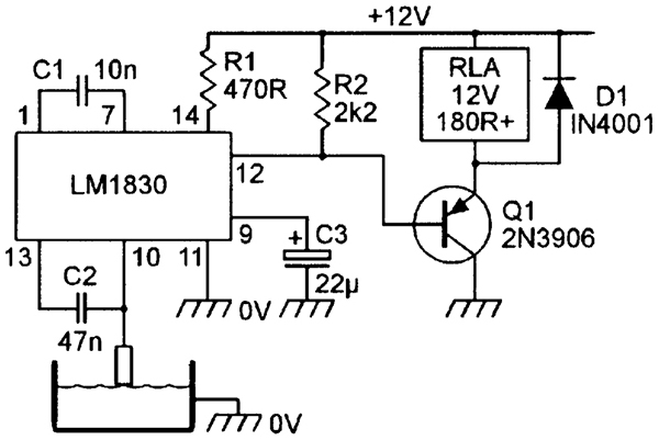
FIGURE 9. Low-level warning circuit with relay output and supply-transient protection.
Finally, Figure 10 shows the relay-driving circuit modified to give an over-level warning action (in which the relay is off when the liquid level is low) by using npn common-emitter amplifier Q1 as the relay driver.
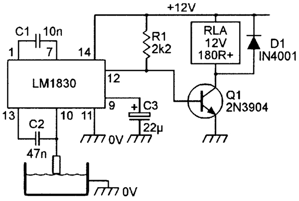
FIGURE 10. Over-level warning circuit with relay output.
A GAS-ACTIVATED ALARM CIRCUIT
Leaking highly-flammable gases such as isobutane, methane (natural or ‘town’ gas), hydrogen, and ethanol, etc., all present potentially explosive and life-threatening hazards, but can easily be detected — even in gas-to-air concentrations of less than 0.5% — by a simple and easy-to-use device that is readily available from major component suppliers and is known as a hot-wire gas sensor. The heart of this sensor is a coil of fine platinum wire that is coated with high temperature oxides and a special catalyzer.
A hot-wire gas sensor actually consists of a pair of thermally matched hot-wire elements, one of which is gas-sensitive and is known as the ‘detector,’ and the other of which is not gas-sensitive and is known as the ‘compensator.’ In some cases, the matched detector and compensator are supplied as individual units, which are each enclosed within an individual fire- and explosion-proof wire mesh, and in others they are combined in a single unit and share a common fire/explosion-proof mesh. In either case, they are meant to be used in the basic circuit shown in Figure 11.
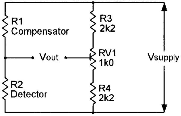
FIGURE 11. Basic gas detector circuit using ‘hot-wire’ gas sensors.
In Figure 11, the compensator (R1) and detector (R2) are wired in series to form a gas-sensitive potential-divider on one side of a Wheatstone bridge, R3-RV1-R4 form an adjustable potential divider on the other side of the bridge, and RV1 is adjusted so that Vout is normally zero.
The compensator and detector have a low hot-wire resistance and, when wired as shown and powered from a suitable voltage source (typically 2.2V or 3V AC or DC), pass a current (typically 150mA to 400mA) that raises the hot-wire temperature to about 350°C in gas-free air.
The resistances of the detector and compensator both vary with ambient temperature and humidity levels, etc., but are matched so that they vary equally in both devices, so that (when wired as shown in Figure 11) they maintain a constant division ratio in the absence of gas.
When gas is present, the detector’s special catalyzer effectively but safely burns the gas that strays within the safety mesh and which surrounds the hot-wire, thus raising the hot-wire’s temperature and resistance, thereby reducing the voltage appearing on the detector/compensator junction and upsetting the balance of the bridge.
This action typically makes the circuit’s Vout value fall by about 25mV at gas concentrations of 4000ppm (= 0.4%) with methane, or 2000ppm (= 0.2%) with isobutane.
Figure 12 shows the circuit of a practical gas alarm that is powered via an external 12V DC supply and which drives a ready-built solid-state commercial alarm/siren unit under the ‘alarm’ condition. Here, the basic gas detector (which is similar to that of the Figure 11 circuit) is built around R2-RV2-R3-R4-R5 and is powered via a stable low-voltage DC supply derived from the 12V line via voltage regulator IC1, and has its output fed to the alarm/siren unit via voltage comparator IC2 and transistor switch Q1.
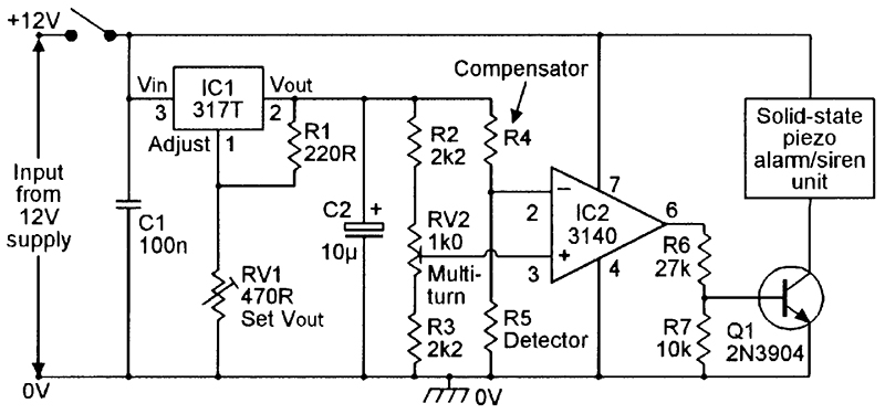
FIGURE 12. Practical gas-detector alarm circuit, powered from an external 12V DC supply.
The circuit’s action is such that the voltage on pin 2 of IC2 is normally about 25mV above that of pin 3 (settable via RV2) under ‘clean air’ conditions and, under this condition, IC2’s output is low and Q1 and the alarm/siren are off, but the pin 2 voltage falls below that of pin 3 when significant gas concentrations are detected and, under this condition, IC2’s output switches high and drives Q1 and the alarm/siren on.
Before starting to build the Figure 12 circuit, first locate a suitable hot-wire gas sensor and find out its voltage and current ratings. With that current rating in mind, select a suitable 12V DC power supply. Now — without wiring the gas sensor in place — build the IC1 voltage regulator section of the circuit, taking care to fit IC1 to a heatsink that will dissipate 1W per 100mA of working load current, and then power it up and trim RV1 so that (when powering a dummy load) it produces the precise specified working voltage of the gas sensor (usually 2.2V or 3V).
Now build the rest of the circuit, fit the gas sensor in place, power the circuit up, and trim RV2 so that the alarm/siren is off. Let the unit warm up for a minute or two, then — using a high-impedance digital multimeter — trim RV2 so that pin 2 of IC2 is 25mV above that of pin 3.
The unit is now set and ready for use, and should activate the alarm if the sensor is temporarily placed in a box and exposed to a modest concentration of gas (such as a brief squirt of butane gas) for half a minute or so. Note that most flammable gases are heavier than air, and that in normal domestic situations, the gas sensor should thus be mounted a few inches above floor level, in a position where it is unlikely to be damaged by passing feet or by the movement of furniture, etc.
A SOUND-ACTIVATED SWITCH CIRCUIT
Prior to the advent of modern highly-reliable PIR movement detectors, sound-activated alarms were widely used in commercial security systems. Most of these alarms were, however, easily false-triggered by the natural sounds that occur inside buildings (such as the cracks or groans that occur as a building cools at night or warms up in the morning) or that originate outside the buildings but are audible within them (such as loud traffic or aircraft noise or thunder).
In some systems, the latter problem was overcome by using internal and external sound detectors and — by using sound-level comparison techniques — only activating the alarm if the internal sounds were louder than the external ones.
Today, sound-activated alarms are rarely used in security systems, but sound-activated switches are widely used. They are used mainly as relay-driving ‘precautionary warning’ devices that switch on a security light and/or a pre-recorded ‘verbal warning’ message or activate a sound- or video-recorder system whenever a suspicious sound is heard in a protected area.
In most of these sound-activated switches, the sounds are picked up via a cushion-mounted electret microphone insert (which thus responds mainly to air-conducted — rather than structure-conducted — sounds) and the resulting signals are then amplified, converted to DC via a rectifier and filter, and then fed to a non-latching relay-driver via a special signal-conditioning circuit.
Figure 13 shows a practical relay-driving sound-activated switch circuit that is powered from a 12V DC supply.
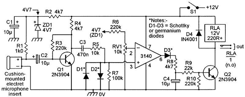
FIGURE 13. Practical relay-driving sound-activated switch circuit.
Here, the cushion-mounted electret microphone insert is powered from a stable 4V7 supply derived from the +12V line via zener diode ZD1, and has its output amplified by common-emitter amplifier Q1 and then passed on to the pin 3 input of the 3140 op-amp via C3-R5. The 3140 op-amp can respond to input signals all the way down to zero volts, and in this circuit is used in the open-loop voltage comparator mode and acts as a super-efficient high-gain signal rectifier that has its ‘threshold’ level (and thus the circuit’s sensitivity) fully variable from zero to +200mV via RV1; note that diodes D1-D2 act as clamps that limit the pin 3 peak-to-peak signal amplitudes to safe values, and must be germanium or Schottky (rather than silicon) signal diodes.
In Figure 13, D3-R8-C4-R9, and R10 act as the unit’s special relay-driving signal-conditioning circuitry. Here, D3 and C4 peak-detect the pin 6 output voltage of the 3140 op-amp, and C4’s resulting charge provides base drive to relay-driving common-emitter amplifier Q2.
Note that C4’s ‘charge’ time (which protects the circuit against activation by brief noise transients) is controlled by R8, and its ‘discharge’ time (which ensures that — once they have been triggered on — Q2 and RLA only turn off again when all noise trigger signals has been absent for a few seconds) is controlled by R9, and that these components provide the circuit with good immunity to false-triggering and relay-chatter problems.
To set up the Figure 13 circuit, connect an analog DC voltmeter between pins 6 and 4 of the 3140 op-amp, then trim RV1 so that the meter reading is zero at low sound input levels, but rises high enough to activate Q1 and RLA at the desired ‘trigger’ sound-amplitude level.
POWER-FAILURE ALARM CIRCUITS
Electrical power-failure alarms can be made to activate when AC power is removed from a deep-freeze unit, or when a burglar deliberately cuts the AC power lines, or when a machine overloads and blows its fuses. Figure 14 shows a very simple relay-output power failure alarm that can activate any type of external alarm device via the relay’s contacts.
Here, the power-line input is applied to a step-down transformer that gives an output of 12V at 100mA. This output is half-wave rectified by D1 and smoothed by C1, and the resulting DC directly powers the coil of relay RLA, which has a coil resistance of 220R or greater. RLA has one or more sets of n.c. change-over contacts that can be used to activate an external alarm device.
Thus, when AC power is applied to the Figure 14 circuit, the relay is driven on and contacts RLA/1 are open, and the alarm is thus off; the circuit typically consumes about 820mW from the AC power lines under this condition. When AC power is removed from the circuit, the relay turns off and its RLA/1 contacts close, thus activating the external alarm.
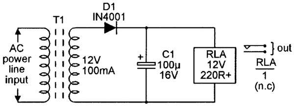
FIGURE 14. Simple relay-output AC power-failure alarm.
Figure 15 shows a power-failure alarm that produces an output in a ready-built piezo siren unit. Here, when AC power is applied to the circuit, the AC input is stepped down to 12V by T1 and is rectified and smoothed by D1 and C1, and roughly 12V DC is developed on the D1-D2 and D2-D3 junctions, and LED1 is illuminated via R1.
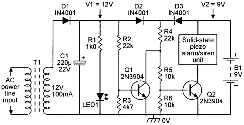
FIGURE 15. Power-failure alarm with a piezo siren output.
Under this condition, Q1 is driven to saturation via R2, and Q1’s collector pulls the R4-R5 junction down to near-zero volts; consequently, zero base drive is applied to Q2, so the piezo alarm is off and no current is drawn from the 9V battery.
When AC power is removed from the circuit’s input, R1-LED1 rapidly discharge C1, and the D1-D2 junction quickly falls to zero volts and Q1 turns off. Under this condition, current reaches Q2’s base from the 9V battery via D3-R4-R5, and Q2 and the siren thus turn on.
Note that the Figure 15 circuit can, if desired, be used with higher battery and T1-secondary voltages, provided that the resulting V1 voltage is at least 2V greater than V2 (the battery voltage).
A PROXIMITY-ACTIVATED ‘ALARM’ CIRCUIT
A proximity-activated alarm is a circuit that activates when a person or large object touches or comes close to a sensing antenna. The antenna may simply consist of a length or loop of wire, or may be a metal object (such as a sheet of foil or wire mesh hidden under a carpet, a safe, or a storage cabinet) that is connected to one end of a wire antenna.
Most proximity-activated alarm circuits work on the capacitive loading principle, in which the gain of an L-C oscillator is adjusted to a critical point at which oscillation is barely sustained and, in which, the antenna forms part of the oscillator’s tank circuit and, in which, the circuit’s 0V supply line is grounded.
Consequently, any increase in the antenna-to-ground capacitance, such as is caused by touching or nearing the antenna, causes enough damping of the tank circuit to bring the oscillator gain below the critical level, and the oscillator ceases to operate. This cessation of oscillation is then used to make the alarm generator activate.
Figure 16 shows a practical relay-output proximity-activated alarm circuit that uses the above operating principle. Here, transistor Q1 is wired as a Colpitts oscillator, with gain adjustable via RV1, and the antenna is coupled to Q1 base via C5. The output of this oscillator, which operates at about 300KHz, is made available at a low impedance level across R4 via emitter-follower Q2.
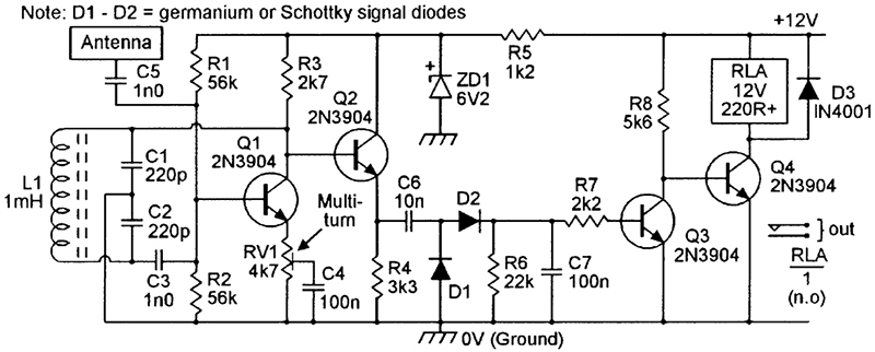
FIGURE 16. Relay-output proximity-activated alarm circuit.
This signal is rectified and smoothed via the C1-D1-D2-R6-C7 network, to produce a positive bias that is applied to the base of Q3 via R7. Q3 is wired as a common-emitter amplifier, with R8 as its collector load, and Q4 is wired as a common-emitter amplifier with the relay coil used as its collector load and with Q4’s base connected directly to the collector of Q3.
Thus, when the Figure 16 circuit is operating normally, the oscillator output produces a positive bias voltage that drives Q3 to saturation and thus removes Q4’s base drive; Q4 and the relay are thus off under this condition. When the circuit’s antenna is touched or externally loaded, however, the oscillator ceases to operate, thus removing Q3’s base drive; Q3 thus turns off; with Q3 off, Q4 is driven to saturation via R8, and the relay is thus driven on under this condition.
Note that the Q1-Q2 section of the circuit is powered via a 6.2V regulated supply formed by R5 and ZD1, thus enhancing the oscillator’s stability. Also note that D1 and D2 must be germanium or Schottky signal diodes, and that the circuit can — if desired — be used to give a directly-driven ‘siren’ output (via a ready-built piezo alarm module) by simply using the siren module in place of RLA and removing D3 from the circuit.
To set up the Figure 16 circuit, simply connect a suitable antenna, trim RV1 so that the relay turns on, then back RV1 off slightly so that the relay just turns off again. Check that the relay turns on again if the antenna is touched or closely approached, and goes off again if the touch is removed; if necessary, trim RV1 for maximum sensitivity.
The final sensitivity of the Figure 16 circuit depends on the setting of RV1 and on the size and type of antenna used. If the antenna is very small, such as a short length of wire, the circuit will act as little more than a touch alarm, but if the antenna is a large sheet of metal foil or wire mesh, the circuit may be sensitive enough to activate when a person approaches within a foot or two of the antenna.
It pays to experiment with different types of antenna, to get the ‘feel’ of the circuit. Remember, however, that the antenna must be well isolated from ground, and that the circuit’s 0V rail must be wired to an effective ground connection.
A TOUCH-ACTIVATED CIRCUIT
Touch-activated circuits are intended to perform some kind of switching action when a person touches a fixed (rather than flexible or mobile) contact point, such as one or more metal studs. The best circuits of this type work on either the capacitive loading principle described in the preceding section of this article or, if they are designed for use only in the general vicinity of AC power lines, are activated by the power-line radiated AC ‘hum’ that is picked up by an electrical contact when touched by a human finger. Figure 17 shows a practical circuit of the latter type.
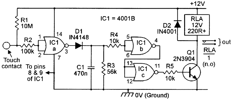
FIGURE 17. ‘Hum-detecting’ touch-activated relay switch.
The Figure 17 ‘hum-detecting’ circuit activates relay RLA when a finger touches a single metal stud or contact point, and is designed around a CMOS 4001B quad two-input NOR gate IC and transistor Q1. Here, gate IC1a is wired as a simple pulse-inverting amplifier and has its high-impedance input terminal taken to the metal touch contact via R2; the contact is biased high via R1, and IC1a’s output is thus normally low.
When a human finger touches the circuit’s contact terminal, its induced AC ‘hum’ signal reaches IC1a’s input, is amplified and inverted, and appears as a large amplitude squarewave at IC1a’s output. This squarewave is rectified and smoothed via D1-C1-R3, is buffered by gates IC1b-IC1c (which act together as a non-inverting buffer), and then drives relay RLA on via R5 and Q1.
Note when using the Figure 17 circuit that its 12V supply must be derived (via an isolating transformer) from the AC power lines, that the 0V supply rail must be grounded, that the relay’s contacts can be used to activate external circuitry or alarms, etc., and that the circuit consumes a quiescent current of only 1µA or so.
The circuit’s touch contact should not be larger than about 10 square centimeters (to avoid unwanted pick-up); if the contact is more than a few inches from IC1a’s input terminal, the connecting leads may have to be screened to avoid unwanted pick-up.
AN ULTRASONIC ‘BEAM’ ALARM UNIT
This unit can be used in the same type of application as an IR light-beam alarm, but works on ultrasonic principles. It consists of an ultrasonic transmitter (Tx), operating at about 40KHz, which is aimed at a matching relay-driving ultrasonic receiver (Rx) unit. When an ultrasonic link exists between the Tx and Rx, the relay is off, but when the link is broken the relay turns on and activates an external alarm or some other electrical or electronic device. This particular unit is a very simple design, with a maximum operating range of only a few yards; it can be used to give security protection to passages and open doorways, etc.
The unit makes use of a modestly priced matched pair of ultrasonic transducers of the type used in many remote-control applications. These devices are normally designed to operate at about 40KHz, and consist of a dedicated Tx transducer and a matching dedicated Rx transducer. Devices of this type are readily available from major electronic component suppliers.
Figure 18 shows the circuit of the unit’s transmitter module, which typically consumes an operating current of 2.5mA from a 9V supply or 3mA from a 12V supply. Here, Q1 and Q2 are configured as an emitter-coupled oscillator, with the Tx transducer used as the emitter coupling element, so that the circuit oscillates at the transducer’s resonant frequency (about 40KHz) and radiates a matching ultrasonic signal.
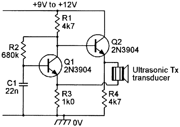
FIGURE 18. Ultrasonic beam transmitter module.
Finally, Figure 19 shows the circuit of the unit’s receiver module. Here, the Rx transducer is pointed towards the transmitter and responds to the transmitted signal in much the same way as a directional microphone. The output of the Rx transducer is fed directly to the base of common emitter amplifier Q1, and appears in amplified form at the Q1 collector.
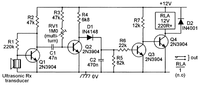
FIGURE 19. Relay-output ultrasonic beam receiver module.
It is then fed, via C1, to the input of an amplifying detector stage that is built around Q2-D1 and C2. Normally, when the beam is unbroken, the output of this detector stage is high, so Q3 is driven to saturation and Q4 and the relay are cut off.
When the beam is interrupted, the output of the detector stage falls to near-zero volts, so Q3 turns off and Q4 and the relay are turned on via R7. An external alarm can be activated by the closing of the RLA/1 contacts. Thus, RLA is normally off, but turns on when the ultrasonic beam is interrupted.
The Figure 19 circuit consumes a typical current of 5mA from a 12V supply. To set up the circuit, turn off the Tx unit, connect a DC voltmeter (with a sensitivity of at least 20KV) across C2, then trim RV1 so that the voltage just falls to near-zero; RLA should turn on under this condition. Now turn on the Tx unit, aim it at the Rx unit, and check that the C2 voltage rises to at least 2V and that RLA turns off.
If desired, RV1 can be further trimmed to obtain absolute maximum operating range. Our next, and last, episode of this series will deal with electronic security circuits designed for use in automobiles. NV