It's almost Halloween — the favorite time of year for electronic hobbyists to show off their skills! If you're like me, anything worth doing is worth overdoing. So, this is the perfect time to complete your decorations with a singing animation of Halloween songs!
Don't look at me that way. There is too such a thing as Halloween songs!
Granted, most people wouldn't go door to door caroling Halloween songs. Personally, I find it less awkward opening the door to people in masks threatening harm if they don't receive processed sugar treats than a group performing an impromptu concert. Do I applaud? Invite them in for figgie pudding? Maybe that's just me.
This Halloween, you can treat your tricksters to both dessert and a show. This project is easy to solder together and uses common tools to assemble. Best of all, the animations for the Halloween songs can be downloaded for free!
Some of you clever readers are probably thinking that this could be repurposed for Christmas. You would be right! In fact, I designed the electronics to be reused for Halloween and Christmas by swapping out the face front for each holiday. It means less work to leave the decorations up without the homeowner’s association complaining that your decorations are out of season. That means more time for Christmas shopping, making cookies, or caroling, if that’s what you’re in to.
There are two parts to this project: lights and electronics. You get to use both your creativity and your logic, so it’s a right brain/left brain kind of deal.
Tools You’ll Need
- Jigsaw with wood blade
- Drill with drill bits and screwdriver
- Sandpaper
- Clamps
- Plastic cutting blade
- Soldering iron
- Tweezers
- 10X Loupe
- Pencil
- Carbon paper for tracing designs (optional)
- String (optional)
- Cans of your favorite food (Yes, really. Optional, but I’ll explain later.)
You’ll also need a 12V LED strip and 12V LED power supply. These can be substituted if the display size changes.
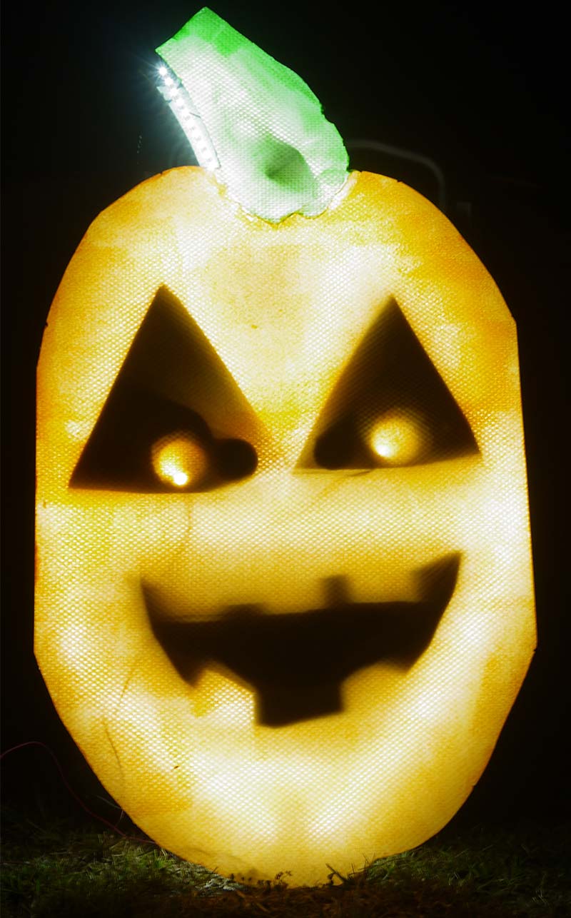
Figure 1. My completed animated display.
Lights
The lights are the creative part of this project. I made a pumpkin face, but you can use your imagination to build whatever scary face suits you: monster, ghost, vampire, or politician.
The face has three animated parts: two eyes and one mouth (unless your imagination takes you in a different direction). Each of these animated parts will have six segments that are lit up with LED strips. “Why does the mouth need six segments if I only need open and closed?” you might be asking. The answer has to do with Preston Blair.
Animating a Mouth
Preston Blair was an animator who worked on some of Walt Disney’s early animated movies. He later worked at MGM and Hanna-Barbera. Blair figured out that of all the sounds an English speaker can make, there are only 10 different mouth shapes that are needed in order to produce them. These mouth shapes mimic natural lip movements and make the singing animation look far more realistic.
When you’re doing a lighting animation, however, you want to get as many of those mouth shapes to appear correctly in the least amount of lights. One approach is to use a separate string of LED lights for each mouth shape, but that’s inefficient.
The clever part of this project is that I figured out how to get all 10 of Blair’s mouth shapes with only six light segments. This is done by adding or subtracting various shapes in order to make the mouth look natural (Figure 2).
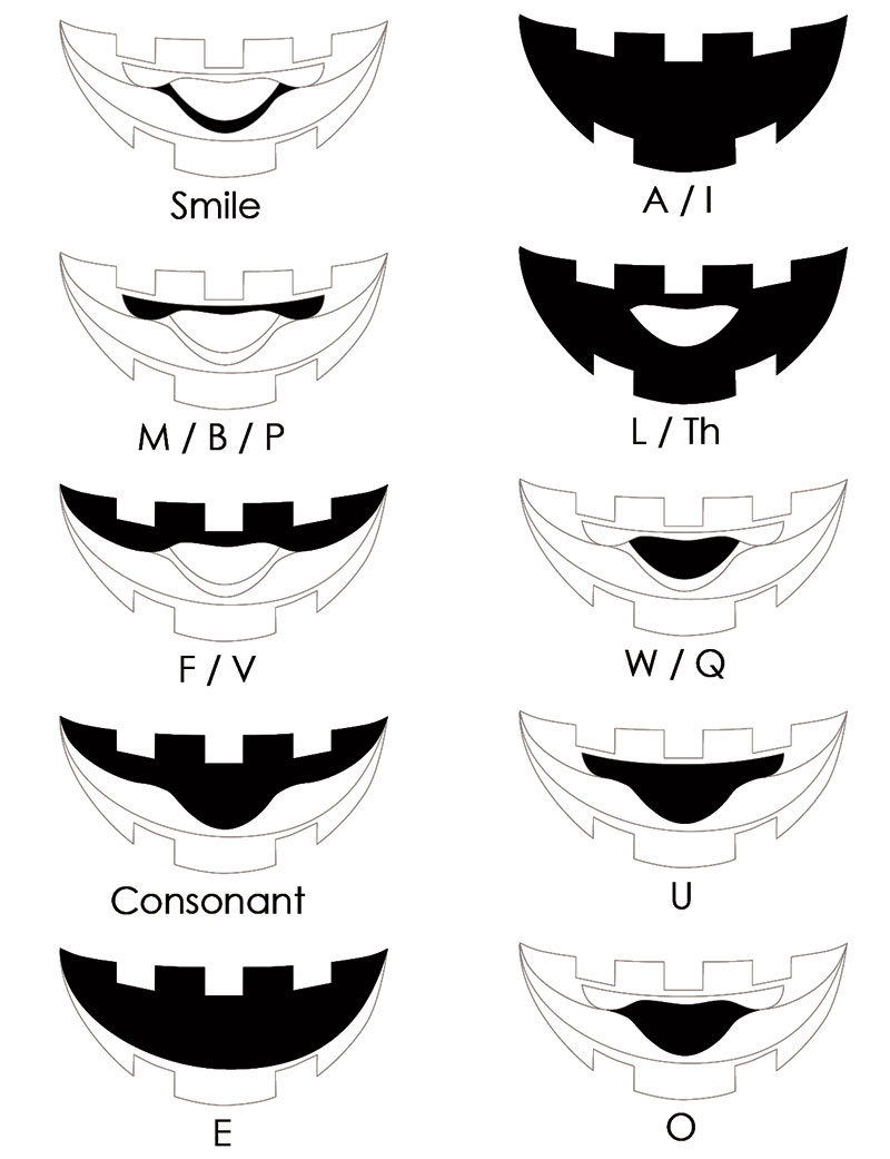
Figure 2. Mouth shapes.
Neat, huh? (Yes, I patented this approach. Feel free to use this design for your own personal projects, but you’ll need to contact me if you want to sell a commercial product based on this.)
Planning for the Animated Display
You could put all of the LED strips on one layer of plywood, and I wouldn’t blame you if you did. My approach is to do a little more work to save a lot more time later. The advantage of doing this is reuse of the electronics and half of the construction.
The reuse approach will divide the animated display into two major elements: the face front, and the light box to hold the LED strips that create the animation. The light box will be reused, and the face front can be swapped out (Figure 3).

Figure 3. Finished animated display parts.
It may be easier to understand this approach if you view the face front and light box from the side (Figure 4).
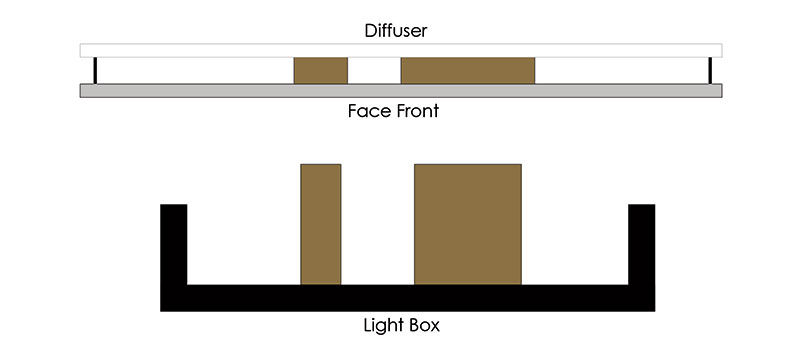
Figure 4. Side view of face front and light box.
The lights extend past the height of the light box and touch the diffuser directly.
I have a small yard, so the size of the animated display I built is about 2’ x 3’. If you have a bigger yard, you’re welcome to scale up the size. The swappable face front has two parts: a light diffuser and MDF backing. The light diffuser is the same acrylic panel that is typically installed in office buildings to diffuse fluorescent lights. They’re readily available at stores like Home Depot in 2’ x 4’ panels (which is why my display is 2’ x 3’).
If you want a larger display, you’ll need to use either more than one diffuser or a frosted piece of plastic. Craft stores sell spray paints that will frost most anything. Files for the eye and mouth segments are available at the article link to use as a reference pattern.
Drawing the Face
Referring to Figure 5, start the face by drawing an ellipse on the MDF backing.
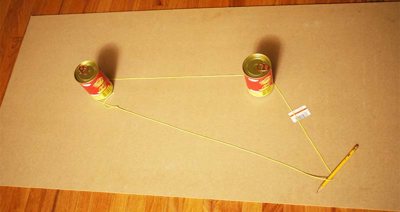
Figure 5. Drawing an elipse.
How do you do this on a large surface area? Math! In order to draw a circle, you’d need a pencil, a piece of string, and an anchor. Put the anchor where you want the center or focus of the circle, tie the string between the anchor and the pencil, then trace the circle by stretching the string as far as it will go. When the pencil goes around a full 360 degrees, you’ll have a perfect circle. So, how do you do this with an ellipse?
If you remember your math (if you don’t, check Wikipedia), an ellipse has two focal points where a circle only has one. You’ll need two anchors to draw an ellipse; food cans work fine. Use the string to tie a loop and place it loosely around both anchors. If you stretch the string with the pencil and go around 360 degrees, you’ll have a perfect ellipse. Move the anchors to change the shape of the ellipse, and increase the length of the string to increase the size.
If you want a more natural face, sketch the opening for the eyes at about the center of your display. Make the opening of the eyes large so you have enough room to incorporate all of the segments for the eye animations. The mouth will be centered between the eyes and edge of your display.
Again, make the mouth large enough to be open with an “ah” shape. You can also download a template that I used to make the face from the article link or pumpkinfx.com. Print it out, then trace the design onto the MDF using carbon tracing paper.
Building the Face Front
Use a drill to make pilot holes in the eyes and mouth on the MDF panel, then use a jigsaw to cut out the shape of your face. Use sandpaper to smooth out any rough spots. Cut out the shape for the diffuser next. The outline of the diffuser should match the MDF panel you just cut, and you can use this panel as a template.
Clamp the diffuser and MDF panel together while you make the cuts. Go slowly in order to prevent chipping on the diffuser. Finish the diffuser by painting on the smooth side with opaque glass paint which is available at a craft store.
You may need more than one coat as painting smooth surfaces is a bit of a challenge.
Building the Light Box
For my light box, I’m using a Sterilite 67 quart underbed box (UPC 073149189585). This works well for a small display because all of the electronics are contained in one box. For a bigger display, you can split the light box into three separate units.
I removed the wheels on my plastic box and painted the outside with black spray paint.
The segments for the animated display need to be distinct from each other. This means that the light from one segment shouldn’t bleed into another segment.
In order to separate the lights, we’ll need to use two of the most magical items used for crafting.
The first is cardboard. It’s cheap, sturdy, lightweight, readily available, easy to cut, forgiving if you make a mistake, and accepts paint extremely well.
The only substance with more magic is duct tape. Its magical properties go far beyond what mere mortal words can describe. There is nothing you can’t accomplish with duct tape. It is the holy relic of the crafting world.
Building the Eye Segments
Place the MDF panel with the eyes and mouth cut on top of the light box. It’s time to create the segments in the eye. Don’t tape the cardboard down until you check its position and add the LED strips. Use three cardboard tubes — like the kind found in paper towels — to mimic movement of the pupil. This is going to allow the eye to look left, right, or straight ahead.
Use a cardboard tube that’s larger in diameter in the middle. This is going to make the face look surprised. Finally, add a cardboard division above to frame the pupils which will make the eyes look angry.
An optional part to make the animated display brighter is to use a sheet of reflective Mylar and tape it down to all of the surfaces you want to illuminate.
Mylar is the stuff that metallic balloons that are caught in power lines are made of. It’s also sold as “space blankets.” You can try to find Mylar locally at an Army surplus store or strangely enough at a hydroponic store. (Why people would ever want to send a plant into space wrapped in Mylar is a topic for another article.)
Aluminum foil could be used as a substitute, but it’s not as reflective. Another alternative is reflective spray paint.
The LED strips that you want to use for your animated display are the 12 volt non-weatherproof cuttable strips (Figure 6).
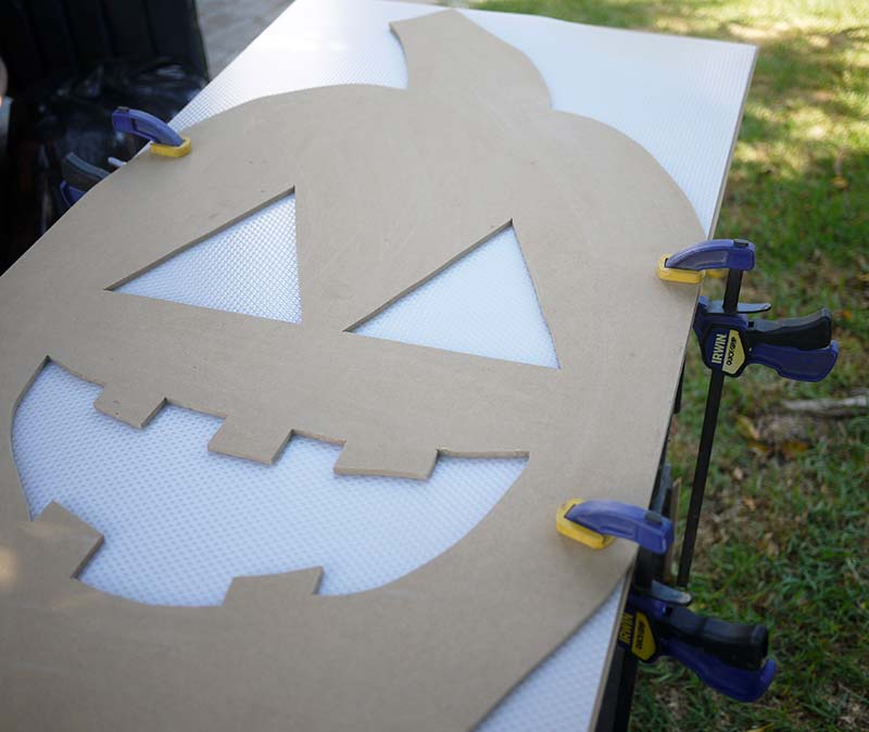
Figure 6. Weatherproof and non-weatherproof LED strips.
There are waterproof LED strips that are cuttable, and at first you’d think that these are the type of strips you’d want to use since this display will be outdoors. However, the weatherproof version of the strips cannot be soldered again once cut as they have a rubber coating on top of the solder points.
The non-weatherproof strips have these solder points exposed, so you can get more segments out of the strip. Cut the strips long enough to line the segments, solder wires long enough to reach the LED controller, then tape down the segments.
Building the Mouth Segments
The mouth segments are a bit more complex than the eye segments, but it’s not difficult once you understand the assembly. From your leftover MDF, cut out two shapes that match the two innermost pieces of the mouth (Figure 7).
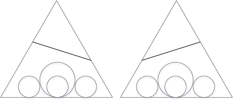
Figure 7. MDF pieces for mouth segments.
Now, line the MDF shapes with cardboard as shown. Tape the cardboard to the MDF cutouts or use a hot glue gun if you don’t mind the occasional burned finger. There should be three segments made from the two pieces of MDF. The smaller shape will be the tongue. This shape will sit on top of the larger one.
The larger shape has two segments. The upper segment is for the lips that are used to make the M/B/P sounds. The lower segment is for the lips in a smile position. Leave the lower piece of cardboard long for the larger shape as it will be used to create the upper part of the middle mouth.
Add one more piece of cardboard for the bottom part of the middle mouth. Add Mylar (if using) and the LED strips like you did with the eyes (Figure 8).

Figure 8. Cardboard mouth segments.
Finishing the Face Front
To finish the face front, cover the front of the MDF panel with Mylar (again, if using) and cut out holes for the eyes and mouth. I’m using spray adhesive to attach the Mylar to the MDF. Use some more LED strips to line the MDF panel so the entire face will be illuminated.
Next, create some standoffs between the MDF panel and the diffuser. The diffuser works better when there’s some distance between it and the lights it’s diffusing. I found that a distance of four inches works well to remove any ‘hot spots’ created by the LED strip.
An optional part is to use some plastic — like a tarp or a plastic bag — to tape up the sides of the face front to reduce exposure to the elements. I live in southern California where it rains very little; we don’t really have ‘weather.’
Finally, attach the face front to the light box with something like eye hooks and bungee cords. Or, if you’re short on time, duct tape will work its magic.
Electronics Setting Up the Raspberry Pi
In the past, it used to take a desktop computer and an expensive controller in order to run holiday light shows. Electronics have gotten much cheaper and more powerful since the first animated light shows, so it’s easier to get started.
Our animated display will be controlled by a Raspberry Pi (RaspPi for short). Even though it’s only $35, it’s a full Linux computer (Figure 9).
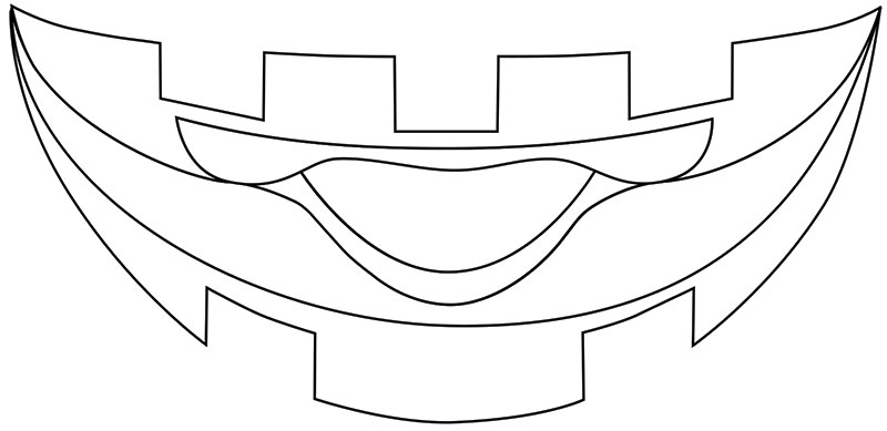
Figure 9. Raspberry Pi.
There are several different versions of the RaspPi. The version I used here is version B, as it has a built-in Ethernet port and more RAM.
The software that will be installed on the RaspPi is a wonderful software package called Falcon Pi Player (FPP), programmed by the talented Chris Pinkham. The software is available from http://falconchristmas.com. In order to install FPP, you’ll need at least a 4 GB SD card (or microSD if you’re using the B+ version) and a USB drive. The SD card will have the operating system and Falcon Pi Player software. The USB drive will be used to store the animations and music.
The RaspPi is fairly particular in how the SD card is formatted for its operating system. The SD card needs to have the format size adjustment off. This is something that Windows 8.1 has some difficulty doing. Fortunately, there’s a utility available by the SD Association called SDFormatter.
The utility was specifically created for formatting external storage like SD cards. It’s available from https://www.sdcard.org/downloads/formatter/.
I haven’t used a Mac to format an SD card for a RaspPi, but based on the research I’ve done it doesn’t seem like there are the same problems that Windows has.
Once you have the SD card formatted, you need to copy the Falcon Pi Player software over to the card. This can be done with a simple drag-and-drop from the .ZIP file you downloaded from Falcon Christmas over to the SD card.
The first time you set up the RaspPi, you need to plug in the SD card, the USB drive, the network cable, and a speaker. There won’t be any animations or songs on the USB drive at this point. The directories will be created when the Falcon Pi Player is first turned on.
Once you have everything connected, you can connect 5V to the USB port to start up the software. If the red PWR LED on the RaspPi is the only LED that’s on, you haven’t pushed in the SD card far enough. It will take about eight minutes for the software to install itself the first time.
Once it’s done, the IP address for the local Falcon Pi Player website will be announced over the speaker. The default IP address is 192.168.0.10. You can connect to the RaspPi via a web browser to check if it’s working. Alan Dahl made a pretty good video tutorial page on how to set up the Falcon Pi Player if you need more help. Those tutorials are available at http://falconchristmas.com/wiki/index.php/Tutorials:_FPP_Setup.
Building the Raspberry Pi Connector
There are two custom printed circuit board (PCB) types for the animated display: the RaspPi connector and the LED controller. Each face will have three LED controllers: one for each eye and one for the mouth. So, there’s a total of four circuit boards.
The RaspPi connector attachs directly to the RaspPi via a 26-pin header (Figure 10).
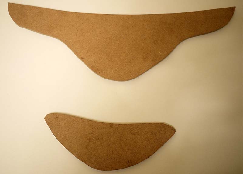
Figure 10. Raspberry Pi connector schematic.
This board takes power from a 12V source. You’ll need a 12V power supply that is used to power the LED strips. I added reverse circuit protection with the Q1.
There’s a clever video on YouTube that explains exactly how this P channel MOSFET protects the circuit without a voltage drain that a diode would take. Watch it at http://youtu.be/IrB-FPcv1Dc.
The RaspPi uses 5V, so the 12V input needs to be converted to a voltage that the RaspPi can use. The parts in the green box on the schematic do this. I tried to use a simple LM7805 voltage regulator, and it got uncomfortably hot. The LM2576 is a much better choice as it doesn’t get hot at all.
The AND gate in the 7408 doesn’t look like it’s doing much. However, the output for the RaspPi is 3.3 volts, and we need to have five volts to guarantee the correct high voltage. The 7408 provides the line level conversion.
Lastly, there’s a standard RJ11 phone jack on the circuit board to connect to the LED controller circuit boards. Since the boards can’t use the telephone to talk to each other, I used the RJ11 connector because it’s still pretty easy to find standard telephone cable even in the age of the smartphone. The four pins used are 12V, ground, a data clock, and a serial interconnect bus (SDO).
When assembled, the RaspPi connector looks like what you see in Figure 11.
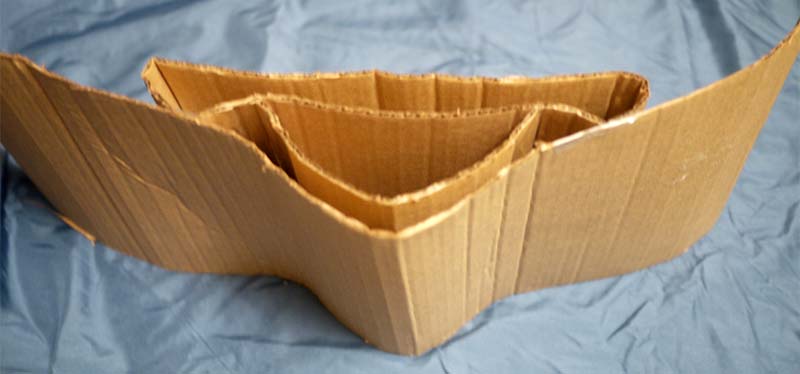
Figure 11. Finished Raspberry Pi connector PCB.
You’ll notice there are leads that are standing from the GPIO header. Don’t cut those off; they’re used to stack any additional boards to connect to the RaspPi.
Building the Controller
The LED controller takes the signals from the RaspPi and turns on the LED strips; see Figure 12.
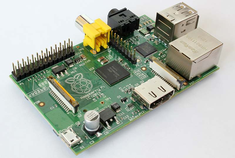
Figure 12. LED controller schematic.
The heart of this controller is the WS2801 from WorldSemi. The WS2801 is very powerful despite its small size. Each IC has its own address based on its position in the series. Not only can each light be turned on individually with a simple two-wire interface, you can also fade lights with 256 degrees of intens
The WS2801 chip is commonly used to change the color of a single RGB LED, but it’s also powerful enough to switch a series of LEDs. The IC can be used anywhere from LED decorative lighting to LCD TV back lighting. This IC sounds too good to be true, right?
Well … There’s one tiny downside. When I say tiny, I mean that the IC is only available as a surface-mount device. WorldSemi used to offer the WS2801 IC in a through-hole DIP package, but stopped a few years back. Why they did this, I have no idea. It seems like the perfect hobbyist LED controller, except for this one tiny problem.
Soldering the IC isn’t actually horrible, to be honest. I’ve soldered a lot smaller ICs. Soldering SMD components isn’t much harder than through-hole components. It’s just a bit different. You’ll need a few other tools in addition to the ones you already have — a smaller tip, a smaller diameter of solder, a bottle of flux, and a magnifying lens (10x Loupe) — in order to check if you soldered everything correctly.
Here’s a good nine minute video on YouTube that shows how to solder SMD components at http://youtu.be/3NN7UGWYmBY.
Think of it this way. You probably already wished that you knew how to solder SMD components but didn’t have a good excuse to do so. Now’s your chance to learn a new skill! A lot of powerful ICs are available in an SMD package only, so this new found skill will give you an even greater list of components to choose from. (Do I sound like a politician yet? Okay, I’ll stop.)
The circuit for the LED controller is fairly straightforward: 12V is converted to 5V with a simple zener diode. The WS2801 doesn’t need as much current as the RaspPi. Power for the LED strip is turned on or off with an NPN transistor. It’s easier to switch off ground than the +12V needed to power the LED strip.
The LED strips are connected to a terminal block that is labeled for each strip. When the PCB is assembled, it looks like what you see in Figure 13.
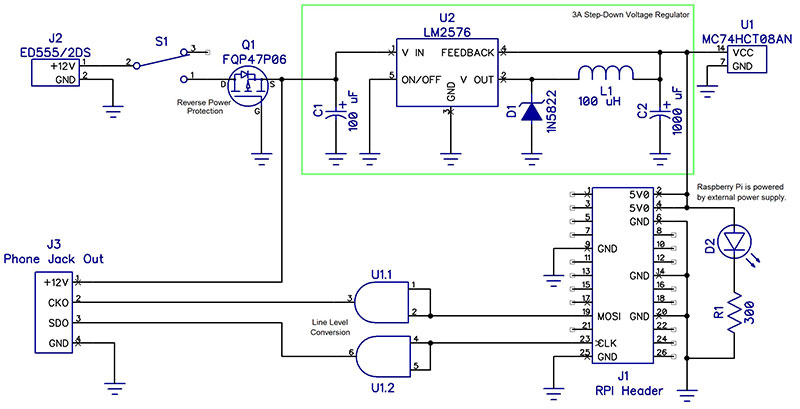
Figure 13. Finished LED controller PCB.
Putting It Together
Wire the LED strips according to Figure 14.
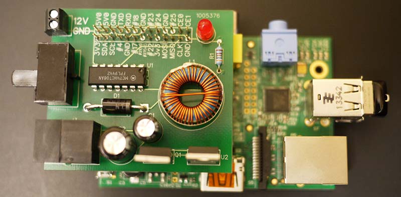
Figure 14. Animated display channel numbers.
Run the telephone wire in the sequence shown in Figure 15.

Figure 15. Wiring diagram.
Remove the USB drive from the RaspPi and insert it into your desktop computer. Download the animation files you’re interested in, then copy those animation files into the sequences directory. You’ll need to provide the music files yourself. If you don’t have the music already in MP3 format, you’ll need to purchase the tracks and download them from Amazon.
Copy the music tracks to the music directory on the USB drive. Return the USB drive back to the RaspPi.
Lastly, you’ll want to connect the 12V power supply to power the LED strips and electronics. You’ll know if everything has power because the power LEDs will be lit on the circuit boards. If not, go back and check your connections.
Happy Haunting! NV
Parts List