Aaaaaaaaaaaaaaaahhhhh!!! I love scaring kids! Ummm, what I meant to say is that I love the spirit of Halloween and giving the trick-or-treaters something fun to look forward to when they come to our house. Okay, the truth is every time I hear them scream, it's a nice little boost to my ego because it means I did a good job in making my Halloween prop!
Underlying Technology: Microcontroller synchronized sound playback, low current to high current buffer system, programmable relay control, microcontroller triggering via passive infrared, driving stepper motors from microcontrollers, microcontroller switching of solenoid valves, and high voltage lighting.
Alternate Uses: Door monitor system at a retirement home that uses PIR to trigger audible voice prompt for an automatic door alert.
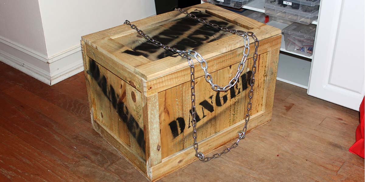
This article is about one prop in particular — the one that the first year I put it out, the kids didn’t need to ring the doorbell because we could hear the screams before they even reached the door! A few kids would not even walk past it to come to the door, so I had to deliver the candy to them! The prop I’m talking about is my Monster in a Box (MIAB from here on out).
The idea behind it is there’s a fire-breathing monster trapped inside a box trying to get out. Now, this is not my original idea. There are several MIAB props out there, although my take on it is a little different than others, and my implementation certainly is. If I can make something more complicated than it has to be, then I’m happy.
Part of my reasoning for making this more complicated is that I'm always dying for a microcontroller project. The question for me is not “How can I make this happen?” It's “How can I use a microcontroller to make this happen?”
Most other MIABs out there involve hacking a drill or some other simple motor to turn a cam wheel with serrations on the edge, then have a cam follower that is attached to the lid which makes the lid go up and down. I saw an opportunity to use a stepper motor and microcontroller right there. I also needed sound and the ability to control a fog machine, strobe light, and a PIR sensor — so a microcontroller was the logical choice.
I’m getting a little ahead of myself. Let’s back up to what I wanted the box to do. First, it had to be triggered by someone walking past it which would activate a whole slew of effects designed to strike fear in the heart of the victim, umm, I mean trick-or-treater.
Those effects would be: the box lid bouncing up and down; a red strobe light and fog machine (the fire breathing part); and a loud screaming animal sound.
A nice side effect of the fog machine is a loud hissing sound which really added to the audio effects of the box. Add some chains to the top to make it look like a dangerous monster is being contained and paint the words “Danger” and “Unknown Species” on the box and we’re a go.
The Brains and Electronics
For the first version of the MIAB, I used a Parallax Propeller prototype board; for the audio, I hacked an old MP3 player. When I retrieved the box for the upcoming Halloween, the MP3 player wasn't working. I either had to hack another MP3 player (which was really quite hard) or find another solution.
Luckily for me, Parallax has their Propeller Activity board which had all the audio stuff I needed right there. The Activity board is the brains of the current MIAB.
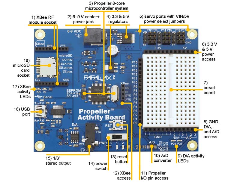
Features labeled.
In order to turn the cam, I decided to use a stepper motor and a Step Stick driver board.
Here, you can see the teeth on the cam.
Initially, I wanted the monster to be in different “phases,” and I was going to slowly turn the wheel back and forth in a slightly curved area of it to simulate a relaxed and “breathing” state where the lid would just slowly raise and lower.
I later scrapped that idea, but still have that ability if I ever want to re-implement it.
For detecting “victims,” I used a PIR sensor. They are very simple and very reliable. Basically, it’s wired directly to pins on the Activity board.
To control the strobe light and fog machine, I needed to use a relay board. The strobe light didn’t even have an on/off button; it was basically just plugged in. So, I spliced the wires and ran them through the relay board. The fog machine was a little more complicated as it had a remote that released the fog once the unit was heated up.
I hacked the remote section and ran that through the relay so the unit would have power to heat up and the relay would simulate pressing the remote button. Your strobe light and fog machine might be different, so it make take some trial and error to figure it out. However, with the Activity board and a relay board, you should be able to control just about anything.
The last bit of electronics which has not been mentioned so far is the audio amplifier. The audio from the Activity board is not nearly loud enough to make the kids jump out of their shoes, so I took apart an old guitar amp and put those parts in the box. (If there were room, I would have put the whole amp in there without taking it apart.) I did not alter the amp in any way, just took it out of its box and put the parts into mine.
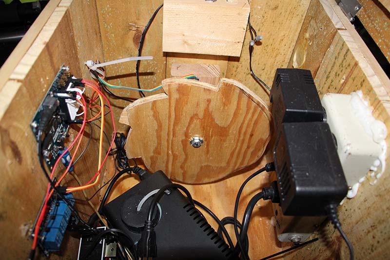
As you can see in the photos, everything was glued and screwed to the sides of the box. I drilled a hole in the back bottom area of the box to run the power cord for the power strip.
Constructing the Box
The first thing I needed was the box — simple enough.
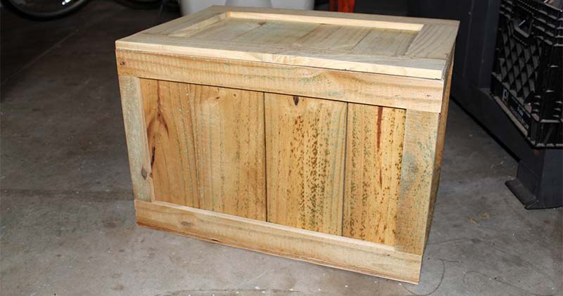
I used some leftover wood from building a fence, but you obviously can choose any kind of wood that you can get your hands on. The specific construction of the box is not important, but I made mine with four panels by laying out the width of the boards that I wanted, and then gluing and tacking the frame boards onto it. I’m not a woodworker, so there are probably better ways to build the box. However, mine is still together after two Halloweens.
Once I had the four panels, I then glued and tacked them together, and then glued and tacked this onto a plywood bottom. I made the top the same way but used hinges to attach it.
My goal was for the box to look like a crate that had shipped from some far away country where monsters still exist. In constructing your box, do some research on crates and pick a style that you like. Just make sure there is enough room for all the stuff that has to go in there to make it work!
The Bouncing Lid Effect
I wanted the lid to bounce up and down frantically, so I borrowed the idea from another MIAB project out there and decided to use a cam follower. Basically, it’s a wheel with peaks and valleys.
Connected to the box lid is a bearing that rides up and down the peaks and valleys when the wheel turns, which makes the lid go up and down. Sharper peaks and valleys will make the wheel turn faster and create a more violent lid motion.
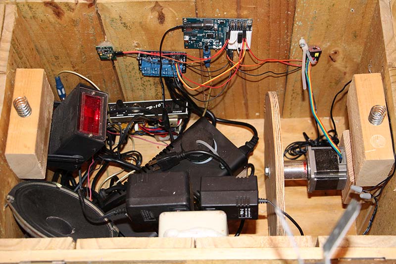
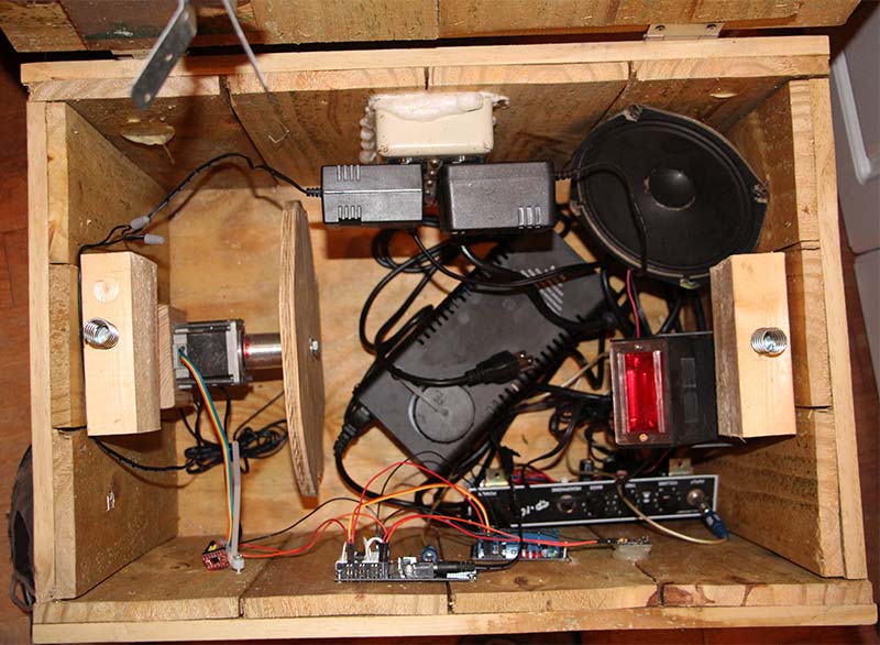
The entire contents of the box.
To construct the cam, I basically took a piece of plywood and used a can to draw a circle. I drew my peaks and valleys coming off the circle, and used my bandsaw to cut it out along the lines. It was not pretty but it worked.
I made a coupling to attach it to the stepper motor shaft, which is basically a piece of aluminum threaded on one end to mount the cam on to and a hole in the other end to mount to the stepper shaft.
Another idea was to glue and tack a block of wood to the cam, drill a hole the perfect size for the shaft, and use a screw to hold it tight. However, I worried this might not last as long, so I opted for the aluminum coupling. If you do not have access to metalworking equipment, this might be a good idea for you.
The Program
The program I wrote to control the whole thing is written in C and is available in the article downloads.
Wiring
As far as wiring is concerned, you can wire things up as you see fit. As long as you change the program to reflect the different pins used, you should be good. Just in case you don’t want to wire things up differently, check out the photos for how mine looks.
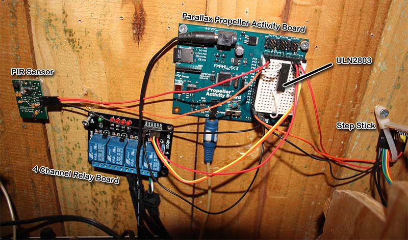
Here’s a look at how things are wired up.
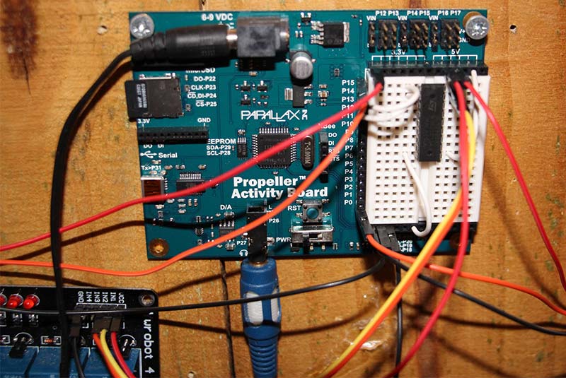
Here's an even closer look at the Propeller Activity board.
Four-Channel Relay Board
- Place the ULN2803 on the breadboard and connect pin 9 to ground and pin 10 to five volts.
- Wire the Propeller pin 13 to the ULN2803 pin 1 (to control the relay channel for the strobe).
- Wire the Propeller pin 14 to the ULN2803 pin 2 (to control the relay channel for the fog machine).
- Wire the GND of the four-channel relay board to GND on the Propeller Activity board.
- Wire the VCC of the four-channel relay board to a 5V supply from the Activity board.
- Wire pin 18 from the ULN2803 to IN 1 on the four-channel relay board (strobe).
- Wire pin 17 from the ULN2803 to IN 2 on the four-channel relay board (fog machine).
- Wire the strobe wires to the first relay block. Pay attention to the Normally Open/Normally Closed configuration. You want the Normally Open jacks (mine were next to each other).
- Wire the fog machine wires to the second relay block.
PIR Sensor
- Wire the PIR sensor GND to a ground on the Activity board.
- Wire the PIR sensor VCC to a 3.3V supply from the Activity board.
- Wire the PIR sensor out to P15 on the Activity board.
Step Stick
- Each stepper motor is different. There are a ton of tutorials out there to figure out how to connect yours to a Step Stick, so wire your stepper motor appropriately.
- I used a wall wart power adapter to provide motor power to the Step Stick. I basically spliced the wires from a wall wart into a female pin header connector. You could solder directly or use jumpers. It is better to give the Step Stick its own power and NOT draw it from the Activity board. While you may get that configuration working, I found it to be a little buggy.
Note: If you are not comfortable or knowledgeable about splicing wires to anything, seek help from someone who does!
- Wire the VCC for the board power for the Step Stick to a 5V supply from the Activity board. Again, you could draw the power for the board from the motor power but I found that buggy, as well.
- Wire pin 0 from the Activity board to the step pin on the Step Stick.
- The Step Stick also requires a few jumpers. You have to at least jumper reset and sleep, or it will not work at all. If you want any form of micro-stepping, then you would have to jumper MS1, 2, and 3 to HIGH.
Audio
- I used a 1/8” to 1/4” cable to connect the audio output from the Activity board to the guitar amplifier.
- I put my animal scream on a mini-SD and plugged it into the SD reader on the Activity board.
So that’s it — an overly complicated Monster in a Box project. It’s probably more of an exercise in using the Activity board to control a myriad of effects than it is on how to most efficiently make a Halloween prop.
If you are reading this article though, I’m guessing you appreciate overly complicated projects just like me. NV
Check out this video of the monster in action, with some upgrades.