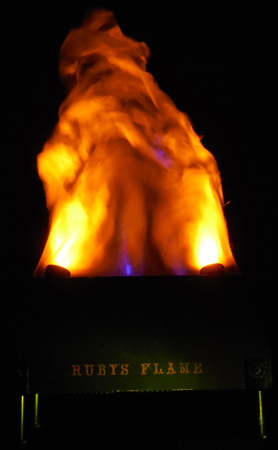
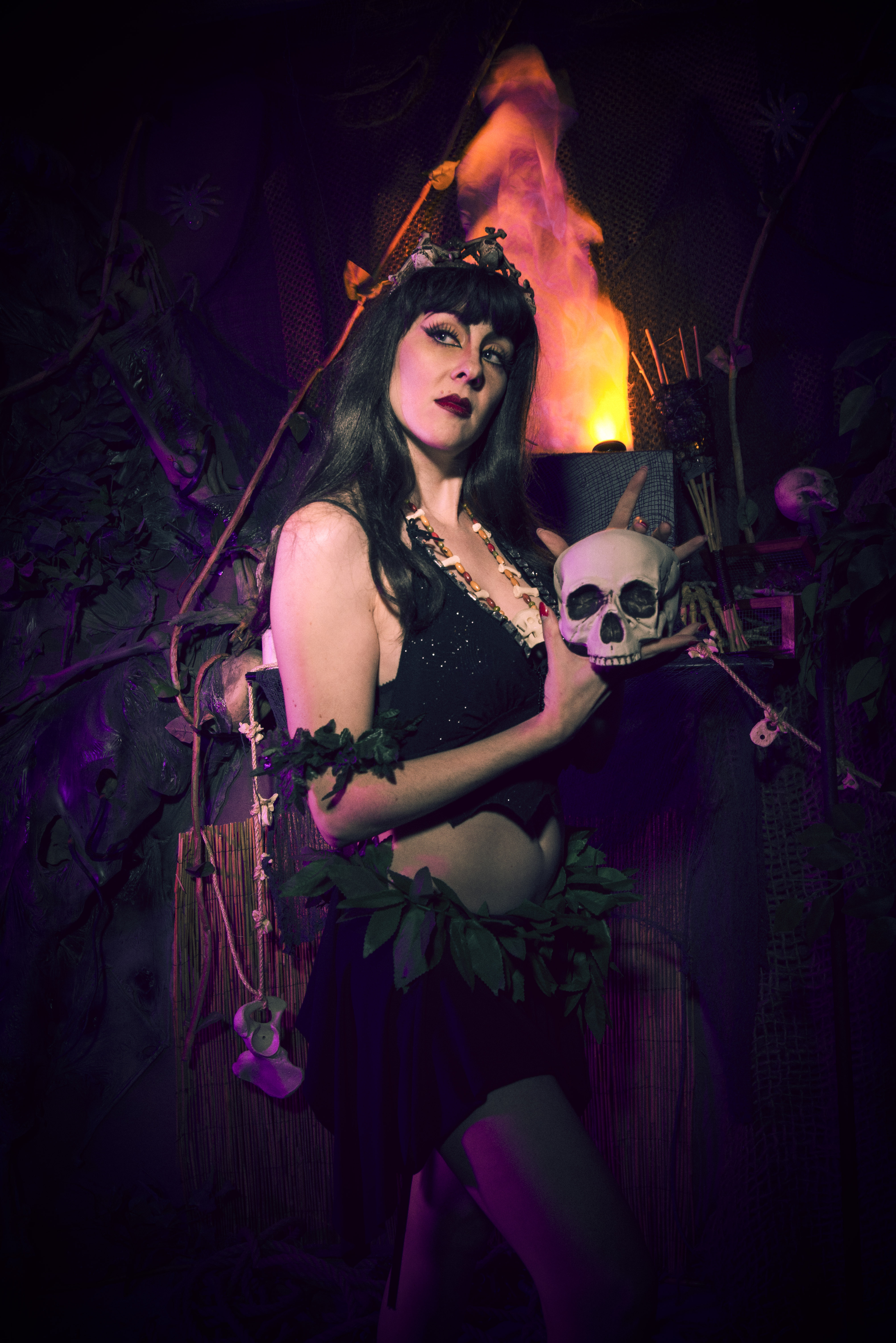
 A friend of ours, Ruby Joule, who is a dancer in the world famous Jigglewatts Burlesque Troupe from Austin, TX, asked if we could help her with a prop she wanted for her stage act. She had been wanting to do something involving fire, but most venues tend to frown upon using real flames. She had seen photos of some of the Halloween props we had built, and asked us if we’d be interested in fabricating something for her. She wanted us to create a four foot tall faux flame prop. It needed to be easy to carry on and off stage by anyone immediately after her performance was completed. This was important as the stage has to be clear for the next act. This also meant it needed to stay cool all the time (no halogens) and be rugged as it would be subject to road life abuse and the occasional clumsy stagehand. We went through a few different designs, but eventually made the stage prop now known as "Ruby’s Flame."
We’ve had a lot of requests from others who have wanted to build this for their home haunts, and recently by a few drama teachers who wanted to use it in some school performances. One of them told us it was the hit of their play. Thanks for the inspiration, Ruby!
Build the MDF Enclosure
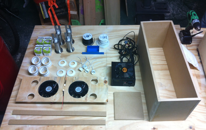
Let’s get started by building the enclosure. Figure 1 shows the parts that will be necessary to complete this. Measurements to build the cabinet itself and the luan top with all the cut information are as follows:
- 2 — Long side panels cut to 23-1/2” L x 9-3/4” H
- 2 — Short panels cut to 7-1/8” W x 9-3/4” H
- 2 — Inside runners for suspending the luan top cut to 22 -1/8” L x 1” W, shelf for PC power supply cut to 6-3/4” W x 7-1/4” L, Luan top cut to 22-1/4” L x 7-1/8 “ W
NOTE: See the section on installing the legs and leg nuts before continuing — it’s a good idea to install the T-nuts that are needed to attach the legs before you assemble the enclosure!
 |
 |
| Figure 1. The parts. |
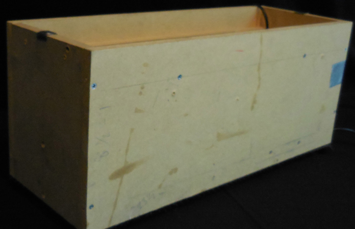
Figure 2. The raw enclosure. |
 |
 |
 |
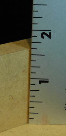
| Figure 3. Side rails measured. |
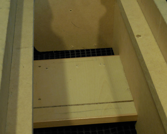
Figure 4. Bottom shelf view. |
Figure 5. Bottom shelf with side rails installed. |
Make the enclosure box by assembling the two long side panels and the two short panels to form a rectangle. The short panels fit inside the long side panels to form this box. Dimensions of the final box will be 23-1/2” L x 8-1/2” W x 9-3/4” H (Figure 2). Use wood glue and secure with wood screws.
Measure 1-1/2” down from the top, inside the enclosure, and attach a runner to each side. This is what will support the luan top panel. Use wood glue and secure with screws (Figure 3).
 |
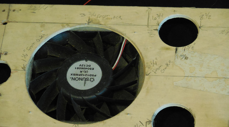 |
Figure 6. Top panel/full view
|
Figure 7. Half of top panel with measurements for the layout. |
Turn the box over so its bottom is facing upright. Measure down 1” and over 3” from the side, then attach the shelf for the power supply so it sits about 1” from the bottom (Figures 4 and 5).
The Top Panel
This is the most important step to the whole project! The panel needs to fit snugly and be measured correctly as it will support the fans, the lighting, and the silk flame itself.
Measure to the center of the luan top and draw a line widthwise to divide the top (dividing line), then draw a second line lengthwise to divide the top again (center line). This will leave you with four sections to measure from. All of your measurements will start there, so make sure that everything is centered (Figure 6).
Each side will need to have one 5” hole and two 1-5/8” holes.
 |
 |
 |
| Figure 8. These marks show where to drill for the LEDs. |
Figure 9. These marks show where to drill for the LEDs. |
Figure 10. These marks show where to drill for the LEDs. |
For the 5” hole, measure from the dividing line along the center line and make a mark at 3-3/4”. This will be the center of the 5” hole for each fan. Repeat this for the other side (Figure 7).
For the two 1-5/8” holes, measure 1- 3/8” from the edge of the top along the dividing line and make a mark. From this mark, you will measure 7-5/8” across the length of the luan top to mark the center of the 1-5/8” hole. The finished hole should be 1/2” from the length side and 2-5/8” from the width side. Repeat this for the remaining three holes. You will also need to drill out two holes for the 10 mm blue LEDs to mount into. We put one LED on each side of the center line and along the dividing line. You will want to drill a hole as in Figures 8, 9, and 10.
Helpful Tip:
Take a scrap piece of luan and drill a hole approximately the same size as the 10 mm LED. You want the hole just big enough so the LED will fit snuggly without gluing it. This way, you will know what size drillbit to use to make the actual hole in the panel. We ended up using a step bit to get the exact size we needed, but I don’t recall what size it was. Using the scrap wood will allow you to figure out what the final hole size needs to be so you can be sure to drill the right size in the actual panel.
Building the Light Harnesses
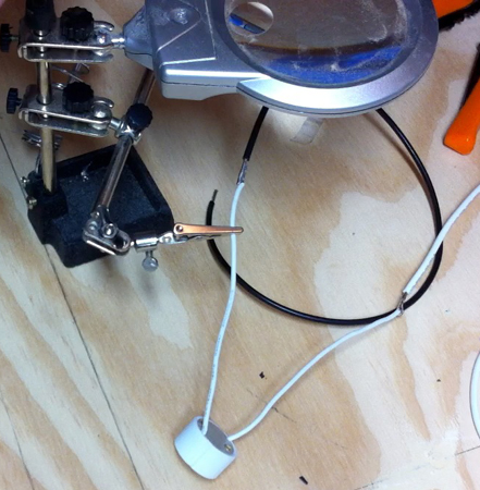
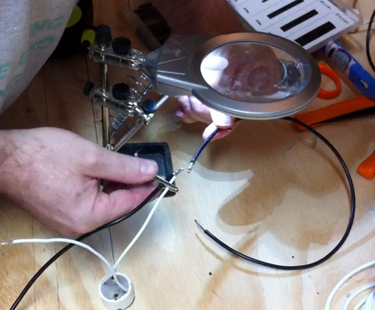
We’ll begin with the light harnesses utilized. Start by taking about one foot of black wire and soldering it to one of the wires from a GU10 socket. It doesn’t matter which wire you use (Figure 11).
 |
 |
 |
| Figure 11. Solder the black wire to the GU10 socket. |
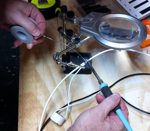
Figure 12. Solder the white wire to the GU10 socket. |
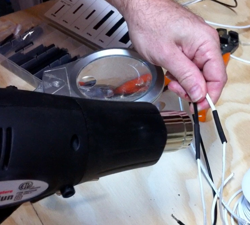
Figure 13. Shrink wrappng the wires. |
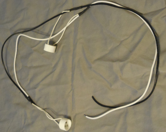
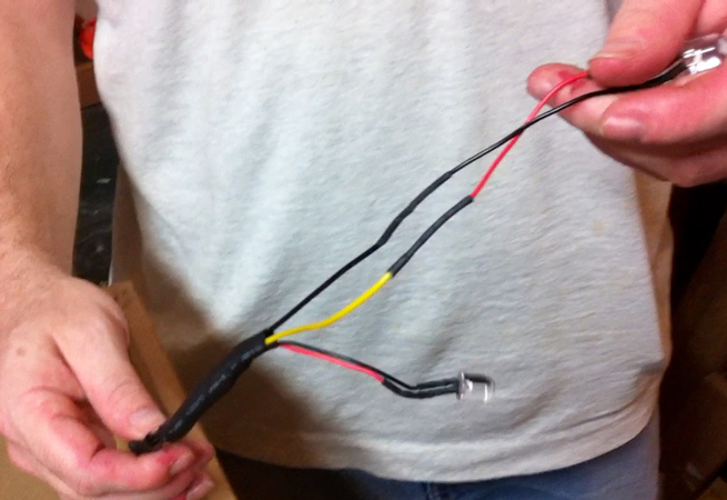
Next, take about one foot of white wire and solder it to the other wire on the same GU10 socket and cover these solder joints with shrink wrap (Figures 12 and 13). You will now need to cut a second piece of black wire approximately one foot long. Solder the two black wires together with one of the wires from a second GU10 socket (Figure 14). Now, do the same thing with a piece of white wire. Cut a second piece approximately one foot long. Take the GU10 socket and solder these wires together with the remaining wire from the second GU10 socket (Figure 15). Shrink wrap both of these solder joints. This will complete the first of two wiring harnesses you will need to make for the GU10 LED lights. Figure 16 shows a shot of the completed wire harness.
 |
 |
 |
| Figure 14. Solder the second black wire to the second GU10 socket. |
Figure 15. Solder the second white wire to the second GU10 socket. |
Figure 16. A completed lighting harness. |
You will need two wiring harnesses, so repeat the steps above and set them aside for now.
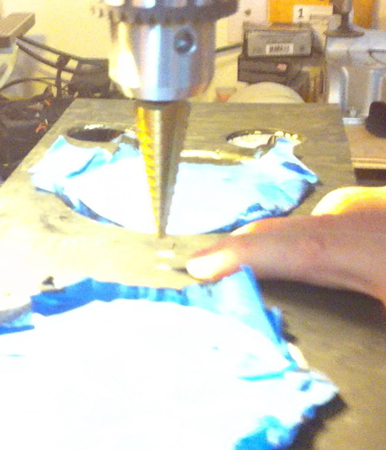
Making the LED SpotLight Holders
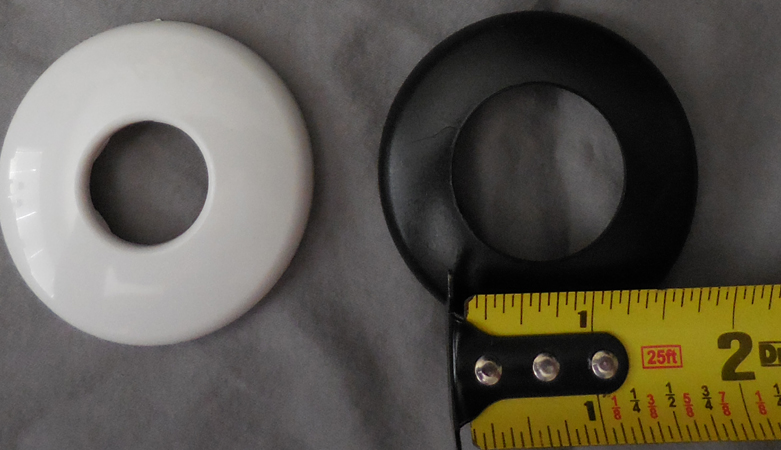
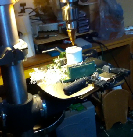
To make the spotlight holders (Figure 17), you will need to use a step drill bit (Figure 18) and enlarge the hole in a shallow flange so the opening is the same size as the lens on the bulb (Figure 19). The easiest way we found to do this is to take a short piece of 1-1/2” PVC and place the flange on top; it will slip over the end of the pipe. Then, drill out the hole with the step bit. The lens on my LED spotlight is about 1-1/4”. If you have a drill press, it will make this easier, but it can be done with a handheld drill if you are careful (Figure 20).
 |
 |
 |
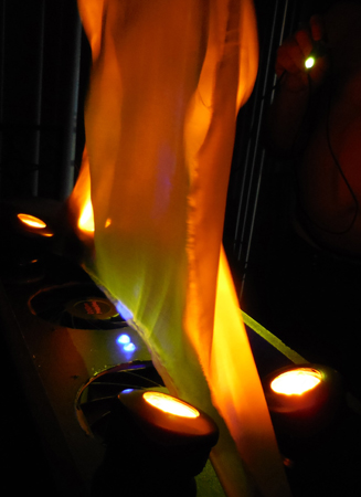
| Figure 17. LED spotlights in action. |
Figure 18. Step drill bit. |
Figure 19. The shallow flanges before and after expanding the size of the hole. |
Repeat this for all four of the necessary flanges, then set them aside for now. We ended up painting all of the parts black so they would disappear when the flame is on. This is a good time to paint parts if you choose to do so (Figure 21).
 |
 |
 |
| Figure 20. Enlarging the hole in the shallow flange with a step bit. |
Figure 21. We painted all the parts and hardware black.
|
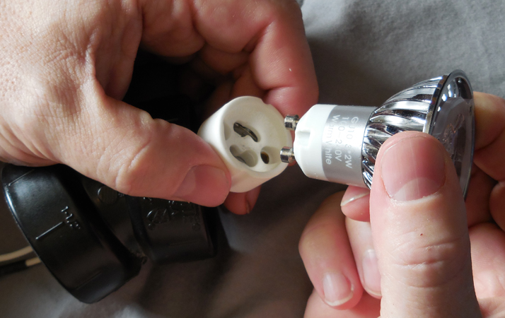
Figure 22. Connecting the GU10 bulb to the GU10 socket.
|
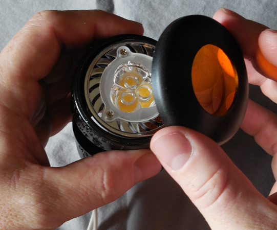
The GU10 LED lightbulbs fit perfectly inside of 1-1/2” PVC/22-1/2 degree angled Els. They are also the perfect angle to shine onto the silk flame. The GU10 socket will come up from below the top panel of the enclosure, through the PVC EL. When the LED is attached, the bulb will sit perfectly inside the angled El (Figure 22). You can then cut a small disc of lighting gel and place it on the bulb to take intense heat away. However, these LEDs barely get warm. Next, take the coupling flange you drilled out earlier and snap it onto the flange to secure the gel and bulb in place (Figure 23).
 |
 |
 |
 |
| Figure 23. Attaching the shallow flange to the PVC light holders. |
Figure 24. Drilling the fan holes with a 5" hole saw. |
Figure 25. We used 1/2" Tek lath screws to attach each fan to the bottom of the top panel. |
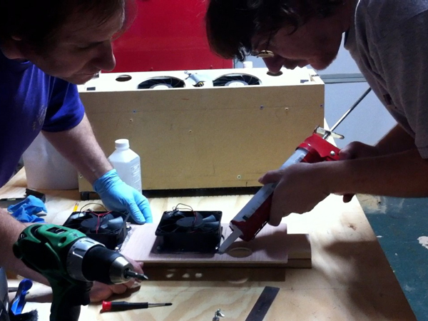
Figure 26. Laying a bead of clear silicone caulking around the base of each fan. |
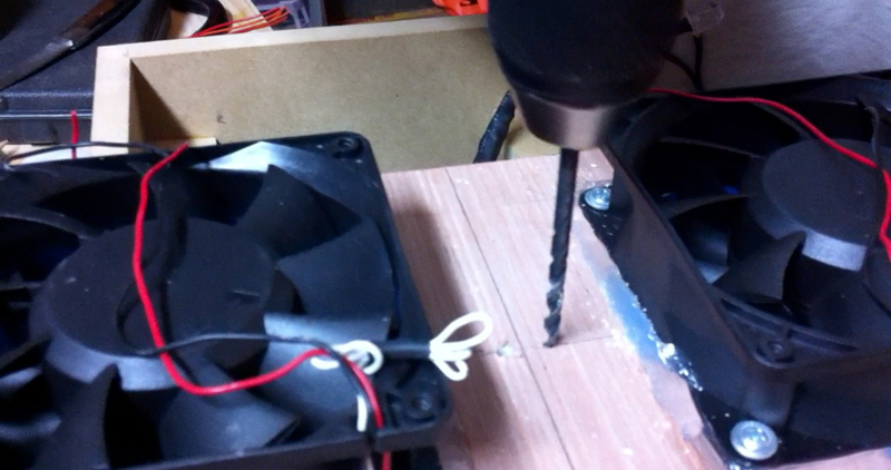
Installing the Fans
The flange itself will lock onto the PVC El, so no glue or fasteners are needed. Besides, you might want to alter the color of the flame at some point. We will eventually position the Els and then glue the base to the top panel of the enclosure, but we’ll do that later once the silk that creates the flames is actually flying. The assembly of the spotlights will be part of the final assembly and wiring.
The particular fans we use are very dangerous when spinning and could probably take off a finger, so always use extreme caution!
The fan’s casing is square and the holes we drilled are round, so we used all-purpose silicone caulking to help plug up around the fans and also to assist holding them securely to the top panel. We’ll use four 1/2” lath screws per fan to secure them, as well.
 |
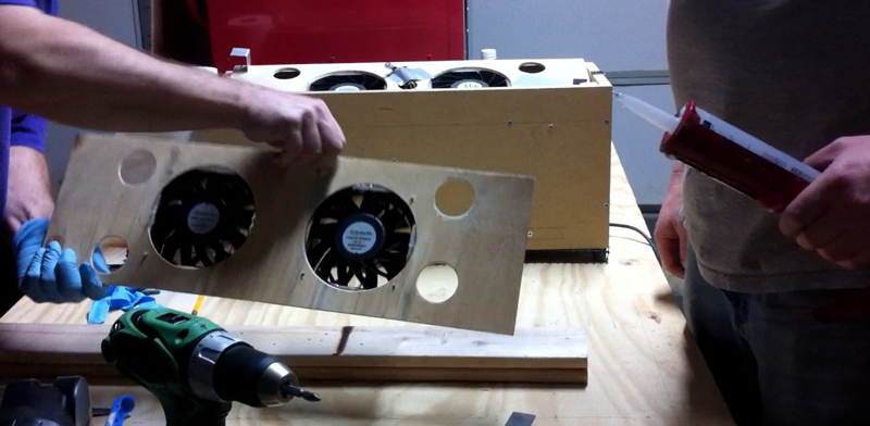 |
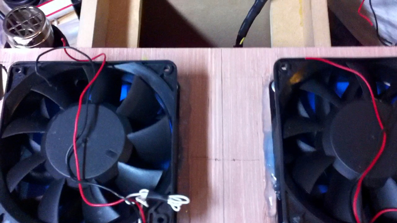
| Figure 27. Both fans mounted to the top panel of our enclosure with screws and clear silicone caulking. |
Figure 28. Flipping over the top panel so we could smooth out the caulking.
|
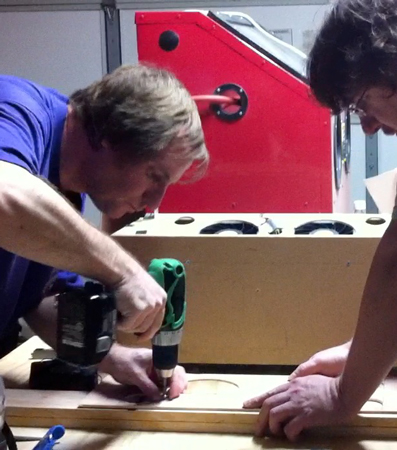
Start by drilling some very small holes into the luan in each corner, lining up with the holes in the corner of the fan (Figure 24). You will need to position the fan so that you can put a screw into each corner to secure it to the top panel (Figure 25). Make sure each corner lines up with the holes in the corner of the fan so you can put a screw into each hole to secure it. You will also want to make sure that the fans are facing the correct direction so when they spin, the air flow will be blowing where it’s supposed to. Usually, the label side is what you want to see when it is mounted to the top and flipped back over to the operating position.
 |
 |
 |
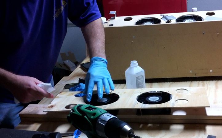
| Figure 29. Smoothing out the caulking using some rubbing alcohol. |
Figure 30. Wiring up the 10mm blue LEDs.
|
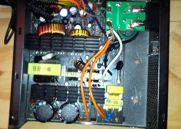
Figure 31. We drilled a small hole in the base of the power supply to attach it to the shelf. |
Make sure to fill in any open spaces around the hole so you don’t lose any air flow (Figures 26 and 27). You can run a thick bead of the silicone caulking around the fan to help seal it. Once this is done, flip the panel over and smooth out the silicone (Figures 28 and 29). Set the piece aside to dry overnight.
Helpful Hint:
Greg showed me a little trick he learned from a tile installer. To smooth out the silicone caulking, put on a nitrate glove and dip a finger into some rubbing alcohol. Then, run your finger over the silicone. The silicone won’t stick to the glove due to the rubbing alcohol.
Continue to Rubys Flame Extended Online Version - Part 2 ...
Downloads
Rubys Flame Extended Article.pdf
Rubys Flame - Extended Version