Continuing from Ruby's Flame Extended Online Version - Part 1...
Hacking A PC Power Supply, Then Connecting Blue LEDs and Fans
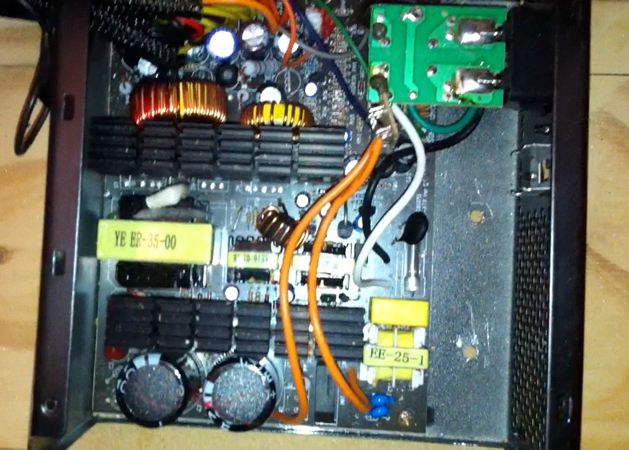
We used a standard ATX computer power supply with two 12V rails since the fans both run on 12V and use a lot of power. We also connected the two 10 mm blue pre-wired LEDs to one of the 12V rails. The LEDs use so little power they can share power with no noticeable loss in performance to the fan or the LED.
For this project, you will only need to use the yellow 12V wires, the one green wire, and the black ground wires. You will also need a 10 watt/10 ohm sandbar resistor. The red wires are 5V and not needed for this build, so they can be cut back and shrink wrapped with the other wires. The two yellow 12V wires will power the blue 10 mm LED lights and the two fans.
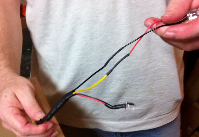
The LEDs we used came pre-wired with a resistor, so we just soldered the red wire from the LED to one of the yellow wires, and the black ground wire from the LED to the other ground wire. Don’t forget to put shrink wrap on the wire BEFORE you solder it. Otherwise, you will have to unsolder it to put the shrink wrap on and then resolder it (Figure 30).
Hooking Up the Power Supply and Splitting the AC Power to the Switch
Let’s look at what we are powering, and what type of power each part uses. The four LED GU10 lights are powered by 110V and the fans and 10 mm blue LEDs get their power from the two 12V rails.
To simplify the operation of Ruby’s Flame, we decided to use the cord from the ATX power supply and run that into a small electrical box we mounted inside our enclosure. This allowed us to splice into the 110V going to the power supply and use it to run the GU10 LED spotlights as well, so we only have one plug to power the whole prop.
It also allowed us to install a switch onto the side, so as Ruby danced by she could flick the switch with her foot or her hand to turn the entire prop on. (Basically, it’s an off and on switch that activates all the lights and both fans at the exact same time to produce the flame effect.)
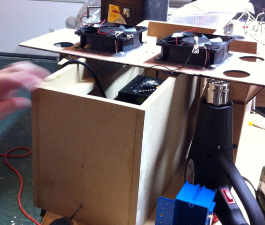
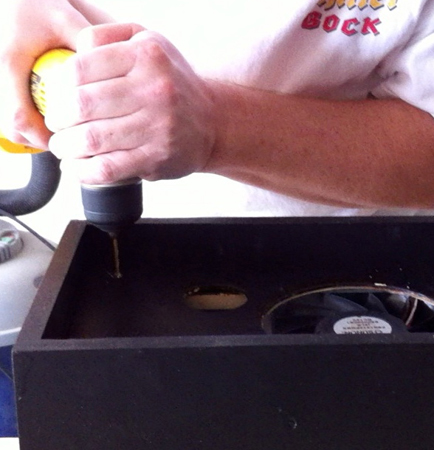
Take your hacked power supply and with the cover removed, drill some small holes in the bottom of the case. Be careful not to drill through anything but the case itself. Now, place the power supply inside of the enclosure (we have a lower shelf installed in ours to attach this to). The power supply needs to be securely mounted to this shelf (Figure 31). We also need to place the electrical box inside the enclosure as far away as possible from the power supply. Set the electrical box aside for now.
 |
 |
 |
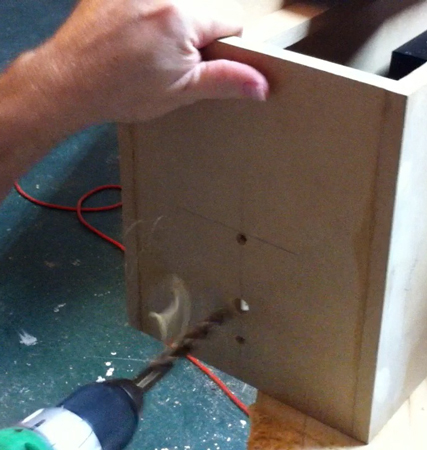
| Figure 32. Drilling a pilot holes in the side of the enclosure to be able to mount the electrical box. |
Figure 33. Drilling out the hole for the switch. |
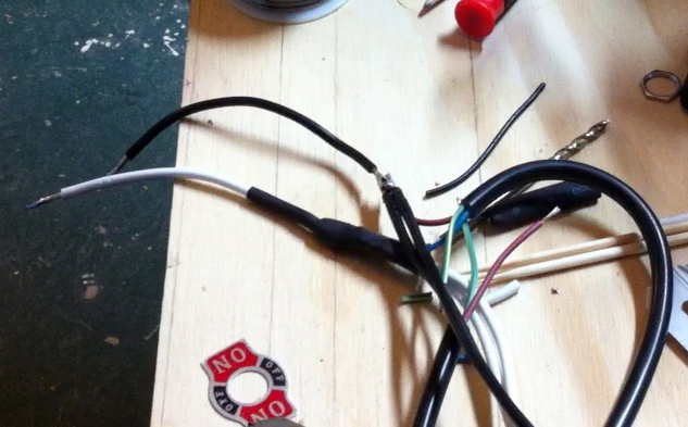
Figure 34. We cut about one foot off of the cord coming from the power supply and stripped the wires. |
Find the center of the side of the enclosure on both the vertical and horizontal positions, then mark your mounting hole location just below the center horizontal line. Drill two small holes in the side of the enclosure that match the spacing of the electrical box; we also counter-sunk the holes (Figure 32). Set the electrical box aside because we’ll run the wiring through it before we actually mount it.
We also need to mount a power switch to the side of the enclosure. Drill the hole along the center vertical lines so that the switch will be centered between the two mounting holes. The size of the switch will determine what size hole you drill, but you want the switch to fit snuggly (Figure 33).
Since we’re only going to have one power cord coming out of the prop, we cut the cord to the power supply about one foot from the plug end, stripped the wire back, and tinned all of it to prep for soldering (Figure 34). We now need to run the wiring into the electrical box so we can solder it all together. On the top and bottom of the electrical box are little knockouts. We’ll need to remove these on one side and feed the cut ends from the power supply through one of the knockouts, then run the two black and white wires from the lighting harnesses through the other knockout and into the electrical box (Figures 35A, 35B, and 35C).
 |
 |
 |
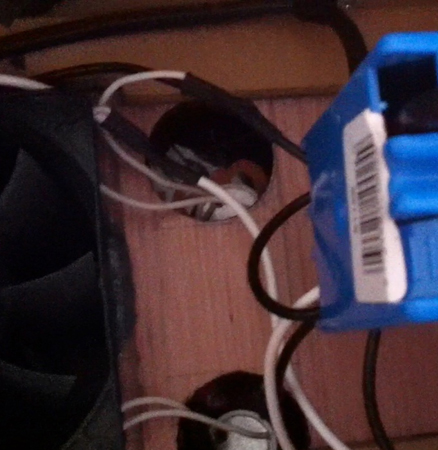
| Figure 35A. This shows how we ran the wiring from the harness and the power supply inot the electrical box knockouts. |
Figure 35B. Wiring the hot wires together with the black wire harness. |
Figure 35C. Wiring the grounds together from the power supply cable. |
Next, take the white wires from the two light harnesses and solder them together with the two common wires: one from the plug end that we cut off and one from the cord running to the power supply. Shrink wrap all these wires once they are soldered. (The common wire is the one coming from the wide spade on the power plug. Of course, not all power supply cords are the same and might have different colored wire for the common. You can use an ohmmeter to see which wire is the common by touching the wide spade with the meter probe to each wire, then watching the meter or listening for a tone to sound when the common wire is touched.)
To connect the black wires from the lighting harness and hot wires together, we will make a pigtail. Cut a piece of black wire about three inches long and solder it together with the two black wires from the lighting harness and the hot wires from the power supply cord. Shrink wrap all of this together, leaving just the end of the new black wire hanging out; this is the pigtail.
The pigtail will need to have a terminal ring added by using crimpers, then crimping the ring to the wire. The ring will attach to the switch, so make sure the ring is the right size for the switch’s screw.
So, now you should have three wires left; two of them are ground wires from the power supply cord. They can be soldered together and shrink wrapped since we won’t be using them. The third wire from the plug end of the power supply cable will be used to connect to the switch. Attach a terminal ring to this wire (it should be the hot wire coming from the plug end that we cut from the power supply cord).
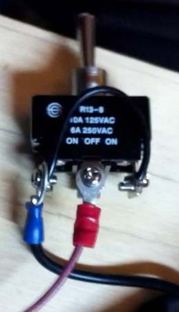
The switch we used is a double pull/double throw and has six screws on it. We will need to take a short piece of black wire (about two to three inches long) and use it as a jumper wire. This will connect to the two end screws so that when the switch is flipped in either direction, it will turn on the prop.
Attach the blue terminal ring from the black pigtail wire to one of the end screws, and attach the red terminal ring from the hot wire coming from the plug to the middle screw. All the wires will be attached on the same side. Do not attach any wires to the other side of the switch. It should look like Figure 36 when wired correctly.
Be sure you make room for the switch! We did run into a problem here. The switch we picked did not have enough threads to go all the way through the side of our wood enclosure. This required us to notch out an area the size of the switch to recess it from the inside of the enclosure and have enough threads stick out to put the nut on to mount the switch.
When completed, the back of the switch should be inside the electrical box, and the power plug will hang down near the side of the enclosure.
Installing the Leg Nuts and the Legs
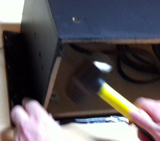
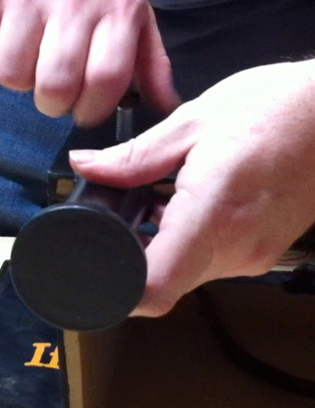
To attach the legs, we decided to use T-nuts (Figure 37). These are nuts you usually find in the specialty hardware drawers at your local home store. We wanted something that would be sturdy and allow us to bolt the legs on so they could be easily removed for travel. You basically drill a hole through the enclosure where you want to mount the legs. The T-nut has a threaded nut that drops into the hole and a flange attached that has little spikes you can drive down into the wood with a hammer.
 |
 |
 |
| Figure 36. Wiring for the switch. |
Figure 37. We used T-nuts to help secure the legs to the enclosure.
|
Figure 38. Hammering in the T-nuts (much easier to do before you assemble the enclosure). |
Don’t do what we did and wait till now to add these to the enclosure. Install the T-nuts before assembling the enclosure. It’s much easier to drive in the little spikes with a hammer when you have some room to swing (Figure 38). If you wait till now to install them, you will find it difficult to get the T-nuts flush with the wood which is preferred for a finished look.
 |
 |
 |
| Figure 39. Bolting on the legs. |
Figure 40. Use a wrench to tighten the legs securely to the enclosure. |
Figure 41. Tightening the nut to attach the switch. |
Once you have the T-nuts installed, you you can simply bolt on the legs as shown in Figure 39. We put the bolt through a large fender washer, then through the mounting slot on the leg, then through the T-nut, and tightened it from the inside of the enclosure with a locking nut. This secures the legs really well (Figure 40).
Securing Wiring, Installing the Top Panel, and Adding a Net
We are ready to start putting all the pieces together and start the final assembly process. Turn the enclosure on its side; the rest of the wiring will be done from the bottom of the enclosure.
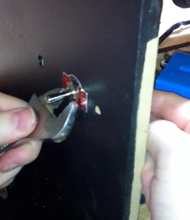
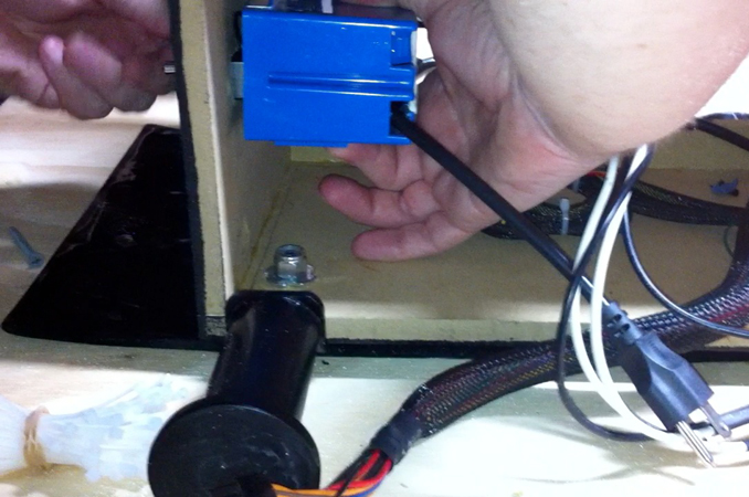
You will need to mount the switch to the side of the enclosure (Figures 41 and 42). Then, you will mount the electrical box inside the enclosure by running screws through it and into the electrical box (Figures 43 and 44).
 |
 |
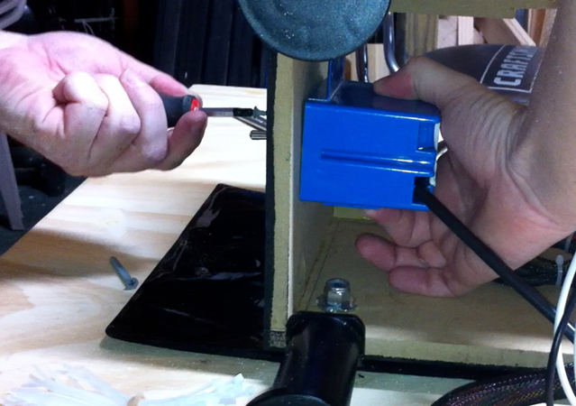 |
| Figure 42. View of the electrical box before it is mounted inside the enclosure. Note that the electrical box will go over the switch to protect the wiring. |
Figure 43. Securing the electrical box with a screw drilled through the pilot holes. |
Figure 44. Another angle showing the electrical box being secured. |
When completed, the back of the switch will be inside the electrical box and the power plug will hang down near the side of the enclosure out of one of the knockouts at the bottom of the electrical box.
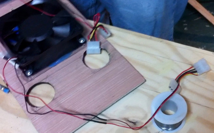
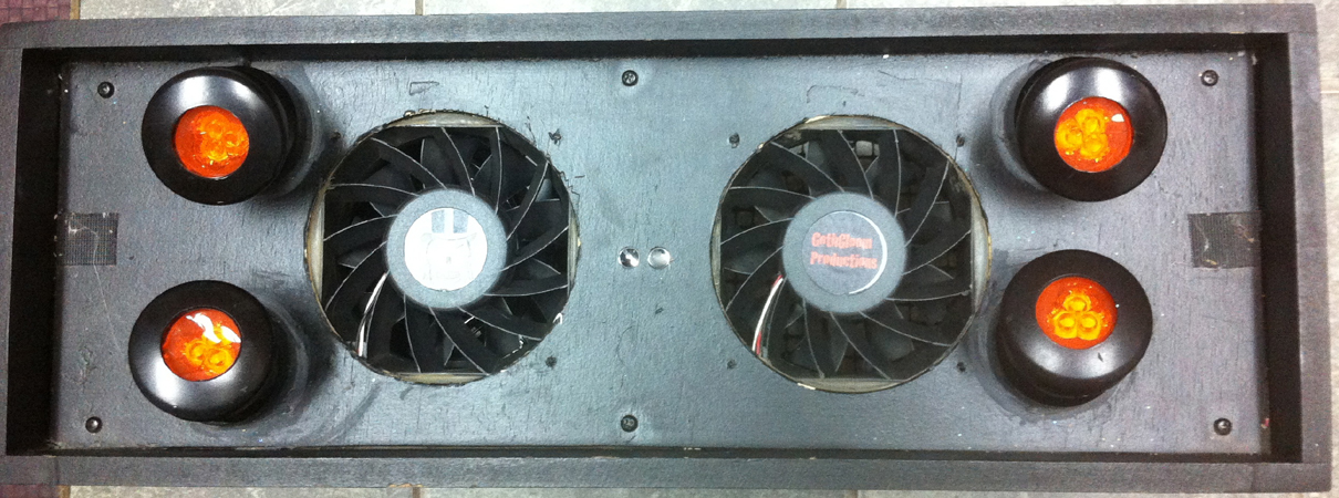
Before we put the top panel on and install the fans, you might want to tie up any loose cables and secure them. You will need to hook up the fans to the power supply at this point (Figure 45). We used some Molex connectors (Figure 46) so we could easily detach the fans if needed. The fans usually will have one red and one black wire. You’ll need to hook one yellow 12V wire from the power supply to the red wire on the fan, and one black wire from the power supply to the black wire on the fan. Place the panel onto the side rails, making sure you have the fans pointed in the right direction. The fans should only be seen through the holes in the panels (Figure 47). Secure them to the side rails by drilling some pilot holes and attaching with screws (Figure 48).
 |
 |
 |
| Figure 45. This photo shows how we added Molex connectors to the wires coming from the fans to be able to easily connect and disconnect them. |
Figure 46. This is a close-up of the Molex connectors we used to hook up the fans. |
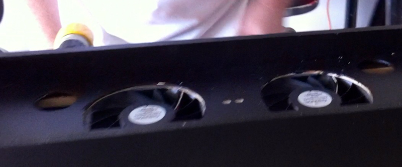
Figure 47. Place the top panel on the side rails, fan side down. |
Next, you’ll want to mount the 10 mm LEDs into the panel. Ours fit snuggly, so we didn’t use any glue.
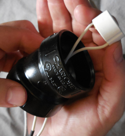
We need to run the GU10 lighting sockets through all four corners of the panel (Figure 49). Take the PVC Els and run the socket through them (Figure 50), then connect one of the GU10 lights to it. Once you connect the light, it will sit in the PVC El and keep the wire from dropping back through the panel (Figure 51). Doing this with four of them was a bit tricky, as we do not want to mount the PVC Els to the panel just yet.
So, now all the wiring should be done; the fans should be hooked up; the 10 mm LEDs should be hooked up; and the harnesses should all be attached. We wanted to test it to make sure everything was done correctly, but before you plug it in be sure you don’t have any wire near any of the fans. Once those start spinning, anything that gets sucked up can damage the fan.
 |
 |
 |
 |
| Figure 48. Drilling Pilot holes in the tiop panel and side rails. |
Figure 49. This is a shot from under the top panel showing the GU10 LED light sockets in the corners and how the wires are run. |
Figure 50. Inserting the GU10 socket through the PVC Els. |
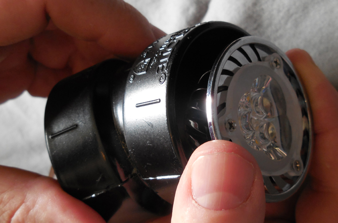
Figure 51. This shows how well the GU10 LED lights fit inside the PVC El. |
We put a safety net on the bottom of our enclosure because we found out the hard way that a fan spinning at a zillion rotations a second can be stopped by a tiny piece of 5 mm Habotai silk (this is what we used as the cloth for the flame). We were testing the silk in the wind coming from the fans, and decided to stop and then start it flying again from a dead-stop position. We shut it off and the silk flame floated down to the top panel with just a bit of it hanging over the edge. We paused a few seconds and flipped the switch to turn it back on, but the silk got sucked up into the bottom of the enclosure. We heard the sound of plastic ricocheting and quickly shut it down. That silk flame had destroyed the fan; it took the blades right off of it while it was spinning.
So, with this in mind make sure to have something like plastic hardware cloth attached to the bottom (Figure 52). It won’t keep everything out, but it will stop the “flame” from getting up in the enclosure. We attached the cloth with screws and washers so if it was ever necessary to get inside to tweak something, it would be easy to do so.
 |
| Figure 52. Buttong it all up and install the plastic hardware cloth. |
Cut and Install the Silk Flame, Then Attach It To the Luan Top With Velcro
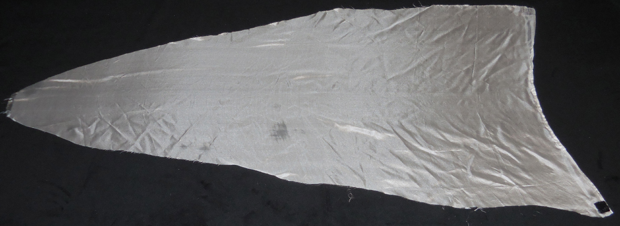
Let’s make the silk flame. Take a piece of Habotai silk and draw out a flame shape as in Figure 53. It should measure approximately 4’ H x 21- 1/2” W when cut out. Notice the curve at the bottom; this was sewed with about a 1/4” hem to give it a little more strength and to catch the wind from the fans better.
 |
 |
| Figure 53. The Habotai silk cut four feet long. |
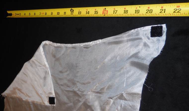
Figure 54. Habotai silk width is 21-1/2". Note how the velcro is sewn on to the opposite sides of the silk. |
Cut out two 1” squares of Velcro™ . Separate the Velcro for the next step. You will need to sew a square of it to each corner. Be sure to sew them onto opposite sides as this is important to make the flame fly straight. Put in a twist at the base of the silk when attaching it to the top panel. You want the soft side of the Velcro sewed to the silk (Figure 54). Attach the rougher half of the Velcro to the top panel as in Figure 55. This will be how we secure the flame to the top.
You may be tempted to want to add additional weight to the flame by sewing the side edges to make it look cleaner or putting stuff on them so they don’t fray, etc. You can ... but it might affect the way the flame flies. We found it best to leave it as natural as possible to get the best look. Over time and use, the silk will fray and wear out but it isn’t that expensive. Just order some extra silk and made a few additional flames just to have on hand to replace as needed.
FINAL CHECKS
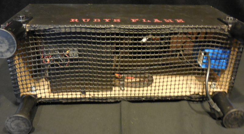
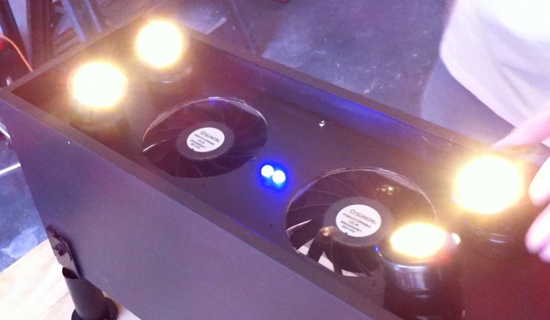
Make sure the switch is in the off position, and hook up the power cord to a power strip with a switch. This allows you to turn on the power from a safe distance until you verify all is good. If you hooked it up right, the fans should be spinning and all the LEDS should be lit up. Don’t worry if the fans sound loud because they are loud; you are moving over 400 CFM of air (Figure 56).
Attaching the LED Spotlights
Now, it’s time to aim the lights and secure them to the top. Since we’re going for a flame effect here, we need to cut some gels. We used different shades of orange until we got the look we wanted. Cut the gels into little circles just smaller than the flanges; place the gel on top of the LED spotlight; and pop the flange on to hold the light and the gel in place (Figure 57). Now, take a couple pieces of Velcro™ and attach the silk to it. There should be a twist in the silk as it goes over the fans; this helps it to fly straight up and down.
 |
| Figure 55. Attaching the velcro to the top panel of the center line. |
 |
 |
| Figure 56. Testing 1.. 2.. 3.. success!! All the LEDs are lit and the fans are spinning! |
Figure 57. Putting lighting gels cut to size into the LED lighting fixtures made out of PVC Els. |
Turn on the switch and the flame should start dancing. Keep you fingers away from the fan blades at all times! Adjust the lights so they shine properly on the flame; it’s best to do this in a slightly darkened room so you can see the effect of the flame. Once you have the lights positioned where you want them, use silicone caulking or glue to attach the PVC Els in their proper place.
LIGHTS OUT ...
Turn off the lights, turn on the “fire,” crank up some spooky tunes, and enjoy! Now, you’ve got your own Ruby’s Flame! NV
Rubys Flame Video