Now that you have a handle on binary logic from Part 1, and how to make simple gate substitutions to solve your custom IC or obsolete part replacement problems, the next step is to put these gates to work for you. You know, the mundane tasks of add, subtract, multiply, and divide. The stuff we learned in elementary school and promptly forgot the moment we pocketed our first calculator.
Unlike "human" math, which is based on the number 10 (a result of having five fingers on each hand), computer math is based on the number 2 — which has the values of 0 and 1. So how do you do math using just nothing and something? The same way it's done using the numbers 0 through 9. The only difference is in the way the 1s and 0s are moved around to fill the needs of borrow and carry.
All binary math operations are built around just two basic circuits: the binary adder and the shift register. While both circuits are made up of several more elementary logic gates, the focus will be on how these two functions perform as a unit. I won't take a microscopic tour of each electron's movement. Instead, I'm going to tell you how to wire the functions together and just what to expect when you flip the switch.
Binary Addition
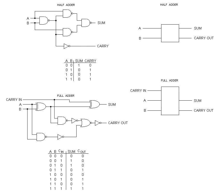
FIGURE 1: Adders and shift registers are the fundamental building blocks of binary mathematical computations.
Basic to all math operations is the binary adder, which comes in two flavors: a half adder and a full adder (Figure 1). The half adder simply tallies two binary bits and outputs a sum. For example:
0 + 0 = 0
1 + 0 = 1
0 + 1 = 1
Nothing surprising here. But what happens when you add 1 + 1? Exactly the same thing that happens when you add 9 + 1 — you get 10. Like decimal addition, binary addition carries over the next most significant digit when the total exceeds the base number. For logic circuits, that's when the sum exceeds 1, whereupon the most-significant digit (MSB) is shifted left one position and a place holder (0) fills the least-most significant (LSB) position. Consequently, the sum of 1 + 1 = 10.
When adding numbers larger than two, a full adder is needed to deal with the overflow, which is called a Carry Out bit. Take the example shown in Table 1 of 1101101 + 101, which has a result of 1110010.
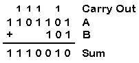
TABLE 1
This operation requires an eight-bit adder, which is easily made using a pair of four-bit full adders, like the 74LS83 shown in Figure 2.
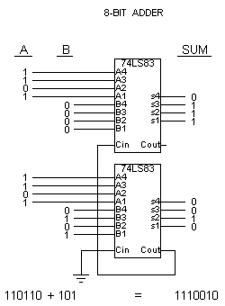
FIGURE 2: Full adders are stacked to process the required word size.
Binary Subtraction
Binary subtraction is interesting in that it uses negative numbers to arrive at a result. For example, if you start with 7 and subtract 5, it's the same thing as adding 7 to -5.
7 - 5 = 2
is the same thing as:
7 + (-5) = 2
It's just a different way of skinning a cat, and a concept that wasn't available until the zero was fully understood. In fact, it wasn't until 1657 that a mathematician (John Hudde) used a single variable to represent either a positive or a negative number. For all those years until 1657, positive and negative numbers were handled as separate special cases. The reason is because we couldn't conceive of there being less than nothing.
Computers and logical math are a lot like our ancestors. They don't understand the concept of less than nothing. For a math circuit to perform an operation, it has to have something tangible to work with. That's why subtraction is such an alien concept. In the computer's eyes, you can't have less than nothing — it doesn't exist (which is true; it only exists in our minds and mortgage ledgers). Boolean algebra solves this dilemma by assigning every number a value — even if that value is negative. In essence, you have a stack of apples, let's say, that need to be added and another stack of imaginary (negative) apples to be subtracted. The second stack doesn't exist in reality, they are merely items to be shuffled about. By matching the apples from the positive stack to those of the negative stack — that is, each time a negative apple mates with a positive apple, both are removed from the total — we arrive at an answer.
Still with me? Let's say we have four apples and we need two apples for another project. The computerese way to do this is to give two of the apples a negative value (-2 apples), while leaving the whole (4 apples) a positive value. These two numbers are now entered into a full adder circuit, which spits out the result of 2.
4 apples + (-2) apples = 2 apples
Simple enough sure, but confusing for a logic gate. Fortunately, there's a binary shortcut that makes the task even easier. It's called 2's complement. If you do a little math here (I'll spare you the details), you'll discover that binary subtraction is identical to adding the A integer to the 2's complement of the B integer. The 2's complement of a number is equal to its NOT (inverted) value plus 1. To find the 2's complement of binary 3, for example, invert 0011 into 1100, then add a 1 (0011 +1) to give 0100 (-3). That's all there is to it. Here's a short list that should give you a grasp of the concept.
Binary 2's Complement
| Decimal Number |
Binary Number |
2's Complement (NOT + 1) |
| 0 |
0000 |
0001 |
| 1 |
0001 |
0010 |
| 2 |
0010 |
0011 |
| 3 |
0011 |
0100 |
| 4 |
0100 |
0101 |
| 5 |
0101 |
0110 |
| 6 |
0110 |
0111 |
Why add a 1 to the inversion, you may ask? For the same reason the new Millennium started at 2001 and not 2000. Logic circuits can't deal with the number zero when doing calculations, just like the calendar can't deal with the gap between 1BC and 1AD — that is, there was either a Christ or there wasn't. One AD represents his presence and 1BC is before his birth. There was never a time in-between. Computer logic is the same way. There is never a time when a number is neither positive or negative — it has to be one or the other. Adding a 1 shifts the inverted number back into the realm of computer comprehension.
The 2's complement conversion can be done at the hardware level using an inverter in series with the B input and applying a 1 to the Carry In line of a full adder (Figure 3). This input is then processed by the full adder to arrive at the difference between the two numbers (A and the 2's complement of B).
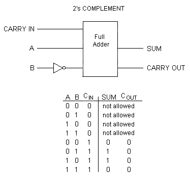
FIGURE 3: A 2's complement conversion can be done by adding an inverter in the B input and applying a 1 to Carry In of a full adder.
Since the subtractor just described is based on a full adder, it's possible to construct a multi-purpose adder/subtractor circuit which performs either addition or subtraction, depending on the presence or absence of a 1 on the exclusive-OR/Carry In line. When Carry In is logic 1, the circuit behaves as a subtractor. Pulling Carry In low (logic 0) causes it to perform as an adder. (In our example of Figure 4, please note that the ADD/SUBTRACT switch goes through an inverter; don't let this NOT hardware gate confuse you when following the above discussion.)
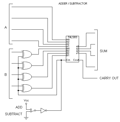
FIGURE 4: With the addition of exclusive-OR gates and a selectable Carry In, a full adder can perform both addition and subtraction.
Binary Multiplication
Any school kid knows that multiplication is simply a series of additions done a specified number of times. For example, 3 x 4 is the same as adding 3 four times over, or 3 + 3 + 3 + 3. With binary multiplication we do the same thing — add up a number the required number of times and arrive at a result.
We also learned very early that there is simple multiplication, where one number is multiplied by a single digit, and compound multiplication, where numbers of two digits or more are multiplied together. Simple multiplication looks like what you see in Table 2, whereas compound multiplication looks like what you see in Table 3.
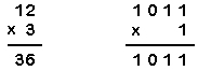
TABLE 2
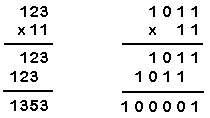
TABLE 3
Notice the shift and add technique which is the signature pattern of compound multiplication. Also notice that it's used with both decimal and binary multiplication. Shifting the position of the line one space to the left is equivalent to multiplying by 2 (binary) or by 10 (decimal). Here's where the shift register, mentioned earlier, comes into play. A shift register is made using JK flip-flops all lined up in a row like dominos, as shown in Figure 5.
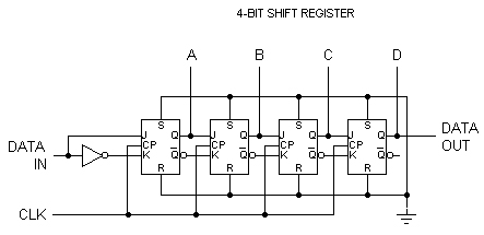
FIGURE 5: A shift register is made using JK flip-flops lined up in a row like dominos.
Let's look at a typical binary multiplication and see where it takes us at. Check Table 4.
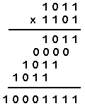
TABLE 4
This is a straightforward calculation using the rules we learned in PS3. The shift register is first loaded with the multiplicand. Then the number in the register is multiplied by the multiplier. After the first line is completed, the register shifts its contents one position to the left and the process is repeated. This continues until all digits of the multiplier are exhausted. Just like doing compound multiplication using decimal numbers, and this circuitry is simple and straightforward, as shown in Figure 6.
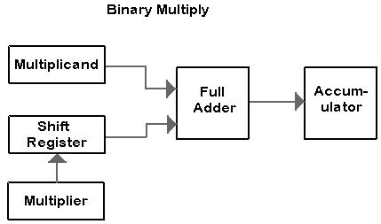
FIGURE 6: A little shift and shuffle can make binary adders binary multipliers.
But if you look at it carefully, you'll see places where the process can be streamlined to better fit the computer community. To begin with, 0 times anything is always 0, so line 2 is superfluous and can be removed. And it's more efficient and faster to do subtotals as lines are added rather than crunch through a tall stack of numbers at the end, which results in the pattern shown in Table 5. As the numbers grow larger, this winnowing process becomes increasingly more efficient, saving both time and resources.
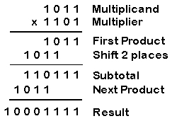
TABLE 5
Binary Division
Of all the arithmetic operations, division is the most complicated and can consume the most resources. In many computer applications, division is less frequently used than addition, subtraction, or multiplication. As a result, some microprocessors that are designed for digital signal processing (DSP) or embedded processor applications do not have a divide instruction. When hardware division is needed, there are several methods to choose from, none of which are stand-outs.
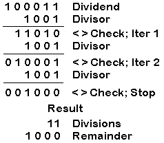
TABLE 6
The simplest is to start subtracting the divisor from the dividend until you run out of numbers to take away from. With this scheme, all you have to do is count the number of iterations — and that's it. For example, look at Table 6 to see how 35 divided by 9 looks in binary using this method. Or, you can do it the old-fashioned way using long division. That is, look at the problem, guess at an answer, test your guess, and respond accordingly. For example, let's take the decimal problem of 448 divided by 17 as shown in Table 7. As you can see, this can be a long-winded process because each iteration takes at least one tick of the clock. Fortunately, there are other options.
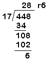
TABLE 7
We can also do long division with logic gates. Basically, it's the opposite of multiplication, where the dividend is shifted right, instead of left, and subtracted from the divisor instead of added. While this seems great in theory, it can get rather cumbersome. A better way is to use 2's complements, and proceed just like before using straightforward multiplication — but with a twist. After each subtraction, a comparison has to be made to determine if the result of the last calculation is larger or smaller than the divisor. See Table 8.
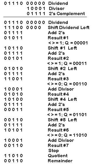
TABLE 8
Yes, the process looks more complicated — and it is! The circuitry, too, is more complex because of the compare and decide logic needed (Figure 7). But it's a lot faster than waiting for a count-down loop to arrive at an answer.
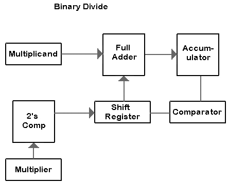
FIGURE 7: And you wonder why many embedded controllers lack the division function.
And The Numbers Are In
Now that you've taken the whole binary tour, I hope that I've touched on something that affects your electronics hobby needs, whether it be scarce part substitutions or basic design. Or, at least piqued an interest or exposed you to something new. Nonetheless, you have to agree that it's so amazing that even the most complex of digital designs are based on three lowly Boolean functions: AND, OR, and NOT. NV