Smiley's Workshop — AVR C Programming Workshop Series - Part 10
Last month, we were introduced to the Arduino and made an LED blink. I’m betting that many of you went off to the Arduino website and played around with other examples. So, you’ve seen The Arduino Way and are now ready to move up to a more advanced ‘Way.’ This month, we learn how to convert Arduino programs into regular C programs that can be used with the Atmel official software: AVRStudio and the semi-official WinAVR and AVRDude. [Note that in the month since our last episode: Arduino moved from version 12 to version 13, and the Duemilanove now uses the ATmega328 — 16k more memory at no additional charge — yeah! There is information at the end of this article on how you can get your very own Arduino Duemilanove and a special components kit for this and future Smiley’s Workshop projects.]
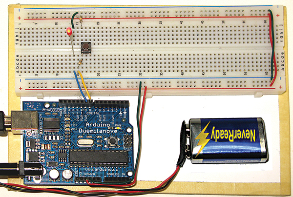 |
| FIGURE 1. The ATmega Learning Platform (ALP). |
Arduino is a combination of ingredients: a hardware platform, a simplified programming language based on C, a PC side IDE (Integrated Development Environment), a set of libraries to ease the use of the hardware, an online community, AND it is all open source. These ingredients lead to a Way of doing things — The Arduino Way that was created for designers (artists) and is excellent for total novices to get started. I want to take the Arduino to the next step, however, to use it as a basis for learning the IMHO ‘real’ C programming language and understanding the AVR hardware. So, let’s move from The Arduino Way (TAW) to A C Way (ACW) and use some of the more standard tools like those discussed in Workshops 1 to 8. Our first task will be to convert that TAW Blink example program shown in last month’s workshop to ACW.
If you want to build the base shown in Figure 1 and a box to carry it around in, see Supplement 1 for this workshop: The Arduino Workshop ATmega Learning Platform.pdf which is available on the Nuts & Volts website (www.nutsvolts.com).
Arduino to ATmega168/328 Pin Mapping
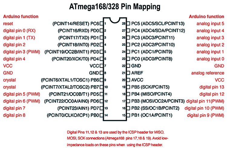
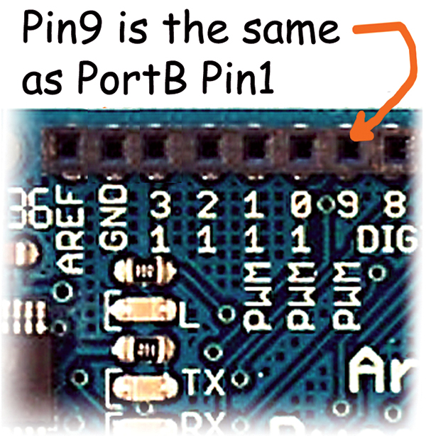
Before we convert the code from TAW to ACW, let’s take a brief look at how the Arduino names the ATmega168/328 pins. This will come in real handy when we want to start thinking about hardware designs using ACW. I/O pin naming is one of the things that Arduino does that is a bit different from what we’ve seen so far. It considers the 14 digital input/output pins as individuals rather than one of eight pins in a port. For instance, as shown in Figure 2 (modified from the Arduino website) and Figure 3, the Arduino pin 9 is the same as the ATmega328 PortB pin 1 (PB1).
 |
 |
| FIGURE 2. Mapping ATmega 168/328 to Arduino pins. |
FIGURE 3. Arduino pin 9 is ATmega328 PortB pin 1. |
Converting the Arduino Blink Example to AVRStudio
We are going to copy the Arduino Blink example to AVRStudio and run it with only a few minor modifications. Last month, we did this example using Arduino pin 13; this month, we will change it to pin 9 so that we can reuse the hardware for a later example.
Before getting started with the code, wire up the ALP with both an LED and pushbutton as shown in the schematic and photo of the layout (Figures 1, 10, and 11). We will use the LED now and the pushbutton later.
 |
FIGURE 4. Add existing source.
|
 |
| FIGURE 5. Files to add. |
If you’ve been following the Workshop, you may have noticed that the Arduino Blink.c program didn’t have the main() function required by C programs. This is one of the simplifications that Arduino takes care of for you (it hides main() in another module). Let’s do this cookbook style:
- Create new directory C:\ArduinoToAVRStudio-Blink.
- Copy the core Arduino .c and .h files to the Blink directory from the Arduino-0013\hardware\cores\Arduino\ directory. (No need to copy the .cpp files.)
- Open AVRStudio and create new project ‘Blink’ in C:\ArduinoToAVRStudio-Blink (where you copied the Arduino files). Creating AVRStudio projects is described in Workshop 2. Be sure and select the ATmega328p.
- Add the Arduino .c and .h files to the AVRStudio project: In the AVRStudio AVR GCC window as shown in Figure 4, click on ‘Add Existing Source’ and then select the files shown in Figure 5. Repeat this process for the header files (also shown in Figure 5).
- Open the Arduino IDE [details in last month’s Workshop].
- In the Arduino IDE, open ‘File/Sketchbook/Examples/Digital/Blink.’
- Copy the Arduino Blink example and paste it to Blink.c in AVRStudio.
- Add
#include “wiring.h” to the top of Blink.c.
- Add the main() function shown below to the file.
- Open the wiring.c module and add to the top of the file:
#define F_CPU 16000000L.
- The AVRStudio project is available in the Workshop10.zip file, (on the Nuts & Volts website).
- Click the AVRStudio compile button.
You will note that you get about 31 warnings and though I never ignore warnings, in this and only this case I will ignore them, because the compiled code works and the only purpose of this exercise is to show us how to move Arduino examples to AVRStudio (TAW to ACW). Later when we write our own libraries to duplicate the Arduino built-in functions, we will not allow warnings to pass unheeded.
#include “wiring.h”
int main(void)<br />
{<br />
    init();<br />
    setup();<br />
    for (;;)<br />
        loop();
    return 0;<br />
}
/*<br />
 * Blink<br />
 *<br />
 * The basic Arduino example.<br />
 * Turns on an LED for one second,<br />
 * then off for one second, and so on...<br />
 * We use pin 13 because, depending on your<br />
 * Arduino board, it has either a built-in<br />
 * LED or a built-in resistor so that you<br />
 * need only an LED.<br />
 * [JP 3/15/09 – changed to pin 9]<br />
 *<br />
 * [url=http://www.arduino.cc/en/Tutorial/Blink]http://www.arduino.cc/en/Tutorial/Blink[/url]<br />
 */<br />
// LED connected to digital pin 9<br />
int ledPin = 9;
// run once, when the sketch starts<br />
void setup()<br />
{<br />
  // sets the digital pin as output<br />
  pinMode(ledPin, OUTPUT);<br />
}
// run over and over again<br />
void loop()<br />
{<br />
  // sets the LED on<br />
  digitalWrite(ledPin, HIGH);
delay(1000); // waits for a second
  // sets the LED off<br />
  digitalWrite(ledPin, LOW);<br />
  delay(1000); // waits for a second<br />
}
Uploading with AVRDude
As we saw last month, the Arduino IDE has an upload button that transparently uses AVRDude to send the hex code to the Arduino board. It does this by calling AVRDude with a script that has all the hard stuff written out for you. That is great if there are no errors — which there probably won’t be when you are doing any of the Arduino example projects. But if there is a problem, you get some bright red text in the serial window at the bottom of the Arduino IDE, and if you are to have any hope of figuring out what happened, you’re going to have to get friendly with AVRDude. Well, that’s not quite correct ... you can post questions on the Arduino forum and maybe get help figuring out what happened, but eventually, to really understand what is going on, you are going to have to learn to use AVRDude. And while that would be a good topic for at least one full Workshop, let me just provide an introduction with a cookbook approach and also recommend that if you are really interested, you can find the AVRDude manual in your WinAVR directory under ..\doc\avrdude\avrdude.pdf. For now, just follow the recipe:
- Go to the Windows Start Button and click on Run, as shown in Figure 6.
-
 |
| FIGURE 6. Start run. |
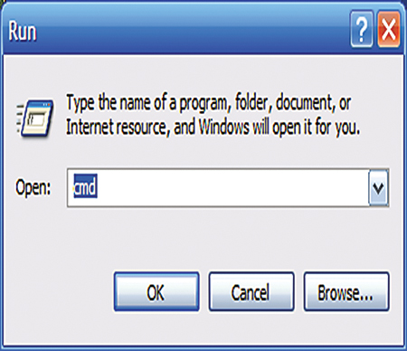 |
| FIGURE 7. Run cmd.exe. |
Open: cmd, as shown in Figure 7.
- You will see the window shown in Figure 8. (If you are a golden oldie, you might say: “Hey, that looks like DOS!” And it sort of is, but not exactly, so be cautious with the nostalgia.)
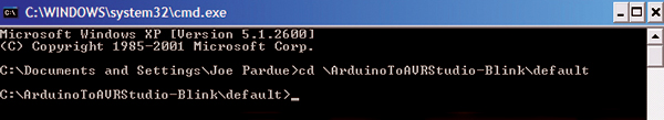
- After the ‘C:\Documents and Setting\YOUR NAME (and, of course, YOUR NAME will be whatever you’ve set it to be and almost certainly not Joe Pardue as in Figure 8), type ‘CD \ArduinoToAVRStudio-Blink\default’ to change the directory. Then, click enter so that you are now ‘in’ the default directory along with Blink.hex.
- Open Notepad or Word or some such program and type:
avrdude -p m328p -c avrisp -P com6 -b 57600 -F -U flash:w:Blink.hex
- Copy this line and paste it following the > in the cmd window as shown in Figure 9: AVRDude Upload. (The reason I recommend typing this in something like Notepad is that I had to correct it four times due to typos, and it is far easier to correct it in Notepad than have to correct it in the cmd window.)
- Note that this line assumes that your Arduino is sitting on com6. If you don’t know how to find the com port it is using, then see: Smiley’s Workshop 10: Supplement 2 — What Serial Port am I using? in the downloads.
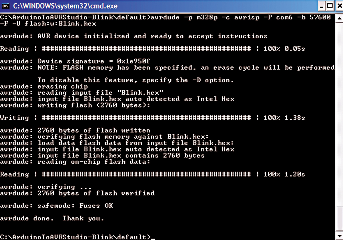
- Finally, get ready to click the enter key and start AVRDude. However, the microsecond before you click enter, push the reset button on the Arduino. The Arduino will reset and look for communication from AVRDude which (because you clicked enter on the PC immediately after you clicked reset on the Arduino) will try to communicate with the Arduino. If you get your timing wrong, however, the Arduino board will tire of waiting and jump from the bootloader to the application program. If you did get it right, you will see the text shown in Figure 9.
- Note that AVRDude ends with “avrdude done. Thank You.” Now that is class! Especially for a free program, so go to their website and donate something!
 |
| FIGURE 8. The cmd.exe window. |
 |
| FIGURE 9. AVRDude upload. |
Press the Arduino reset button and pin 9 should blink once per second. We have now done the Blink example TAW last month and converted it to ACW this month.
Next, we will start doing some hardware projects that let us convert more of the Arduino examples from TAW to ACW.
Debouncing a Pushbutton
Converting the Arduino Debounce example to C for AVRStudio is much like converting the Blink example, but I want to repeat the steps — condensed a bit — to help reinforce the conversion process:
- Create new directory C:\ArduinoToAVRStudio-Debounce.
- Copy the core Arduino files to our Debounce directory from the Arduino-0013\hardware\cores\Arduino\directory.
- Create new AVRStudio project Debounce in C:\ArduinoToAVRStudio-Debounce.
- Copy the Arduino Debounce example to Debounce.c in AVRStudio.
- Change the inPin from 7 to 8:
int inPin = 8; // number of the input pin
- Change the outPin from 13 to 9 and
outPin from: int outPin = 9; // number of the output pin
- Add #include “wiring.h” to the top of the file.
- Add the main() program shown in the Blink source code above.
- Compile and don’t worry about the warnings.
- Go to the Windows Start Button and click on Run.
- Open: cmd.
- After > type
cd C:\ArduinoToAVRStudio-debounce\default.
- After > type:
avrdude -p m328p -c avrisp -P com6 -b 57600 -F -U flash:w:Debounce.hex remembering that your device may not be on com6.
- Press the reset button on the Arduino and the enter key on the PC.
The AVRStudio version of the Debounce code is also available in the Workshop10.zip. And, as a reminder, yes — this is harder than using the Arduino IDE, but it provides a clear path to C programming using the Atmel official tools, which is the direction I’ll be going with future Workshops.
 |
 |
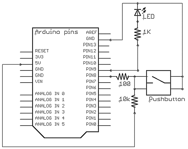
| FIGURE 10. Schematic for LED and pushbutton. |
FIGURE 11. Close-up of LED and pushbutton breadboard layout.
|
Push the button and the LED state toggles between on and off. That was fun, and now, as shown in Figures 10 and 11, you have what is essentially a very expensive light switch, but who said learning was cheap?
Using PWM to Fade an LED
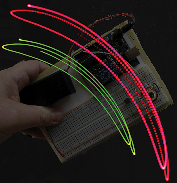 |
| FIGURE 12. PWM Fade. |
We can use the LED attached to pin 9 to demonstrate PWM (Pulse Width Modulation). Figure 12 shows the ALPs being waved up and down with the LED fading in and out. Notice that the red streaks seem like beads whereas the green streaks are smooth. This is because the red LED is being turned on and off every ~33.3 times per second, with the on time varying. The camera lens was left open to capture several hundred of those intervals. Look at the center of the red streaks and you will see each red ‘bead’ gets progressively brighter until they seem to blend in the brightest part of the sweep.
The concepts behind PWM are worthy of a full Workshop (or two), but as you will see from the source code, it is actually a fairly simple concept. There are two loops: one for fading in and the other for fading out. Each loop steps through 0 to 255 in increments of five and uses that value in the Arduino analogWrite() function that sets the length of time the LED is turned on in each cycle. When you look at the LED sans shaking, it seems to brighten and fade smoothly since the eye/brain smoothes out rapidly blinking lights. This phenomenon is called persistence of vision (POV) and is the same thing that makes movies and TV seem to move smoothly when, in fact, you are seeing a sequence of still images.
For this exercise, we will assume that you learned enough in the first two examples to convert the Arduino Fading example code yourself (if not, you can find the converted example in Workshop10.zip). Please note that when I did this last example, I forgot to close the Arduino IDE — which had the com port open causing an AVRDude synch error — AND I forgot to add the F_CPU to the wiring.c file. You have to be patient and persistent doing this kind of work. So, don’t feel too bad when you make the inevitable dumb mistakes like I make. It is part of the process, so learn to enjoy it. NV
Downloads
Smiley’s Workshop 200905 (Workshop10.zip)